Sélection de la langue

Search

Sommaire du brevet 2086870 

Énoncé de désistement de responsabilité concernant l'information provenant de tiers

Une partie des informations de ce site Web a été fournie par des sources externes. Le gouvernement du Canada n'assume aucune responsabilité concernant la précision, l'actualité ou la fiabilité des informations fournies par les sources externes. Les utilisateurs qui désirent employer cette information devraient consulter directement la source des informations. Le contenu fourni par les sources externes n'est pas assujetti aux exigences sur les langues officielles, la protection des renseignements personnels et l'accessibilité.

Disponibilité de l'Abrégé et des Revendications

L'apparition de différences dans le texte et l'image des Revendications et de l'Abrégé dépend du moment auquel le document est publié. Les textes des Revendications et de l'Abrégé sont affichés :

  • lorsque la demande peut être examinée par le public;
  • lorsque le brevet est émis (délivrance).
(12) Brevet: (11) CA 2086870
(54) Titre français: COMMANDE DE FREIN DE STATIONNEMENT ELECTROHYDRAULIQUE
(54) Titre anglais: ELECTROHYDRAULIC PARKING BRAKE CONTROL SYSTEM
Statut: Périmé et au-delà du délai pour l’annulation
Données bibliographiques
(51) Classification internationale des brevets (CIB):
  • B60T 13/22 (2006.01)
  • B60T 07/12 (2006.01)
  • B60T 13/58 (2006.01)
  • B60T 13/66 (2006.01)
(72) Inventeurs :
  • JOHNSON, DOUGLAS RENE (Etats-Unis d'Amérique)
(73) Titulaires :
  • DEERE & COMPANY
(71) Demandeurs :
  • DEERE & COMPANY (Etats-Unis d'Amérique)
(74) Agent: BORDEN LADNER GERVAIS LLP
(74) Co-agent:
(45) Délivré: 1996-07-30
(22) Date de dépôt: 1993-01-07
(41) Mise à la disponibilité du public: 1993-07-22
Requête d'examen: 1993-01-07
Licence disponible: S.O.
Cédé au domaine public: S.O.
(25) Langue des documents déposés: Anglais

Traité de coopération en matière de brevets (PCT): Non

(30) Données de priorité de la demande:
Numéro de la demande Pays / territoire Date
822,766 (Etats-Unis d'Amérique) 1992-01-21

Abrégés

Abrégé anglais


A spring-applied, pressure-released parking brake is
controlled by an electrohydraulic control system. A solenoid
operated parking brake control valve and a manually operated
tow control valve control communication between the engine
driven pump, the sump, the operator driven pump and the
release chamber of the parking brake so that the parking brake
can be released and applied during normal operation of the
engine driven pump and so that the parking brake can be
released by operation of the operator driven pump when the
vehicle is shut down. A transport sump valve and an inlet
check valve operate to prevent the parking brake from engaging
while the vehicle is moving too fast, as a result of operator
error, hydraulic failure or electrical failure.

Revendications

Note : Les revendications sont présentées dans la langue officielle dans laquelle elles ont été soumises.


THE EMBODIMENTS OF THE INVENTION IN WHICH AN EXCLUSIVE
PROPERTY OR PRIVILEGE IS CLAIMED ARE DEFINED AS FOLLOWS:
1. In a brake system having a spring-applied, pressure-released parking
brake having a release chamber, a control system for controlling operation of the
parking brake, the control system comprising:
an engine-driven pump for supplying pressurized fluid;
a sump;
an operator-driven pump for supplying pressurized fluid in response to
manual operation thereof; and
valve means for controlling communication between the engine-driven
pump, the sump, the operator-driven pump and the release chamber so that the
parking brake can be released and applied during normal operation of the engine-driven pump and so that the parking brake can be released by operation of the
operator-driven pump when the engine driven pump is not operating;
the valve means comprising:
a parking brake control valve for normally communicating fluid from the
engine-driven pump to the release chamber and for communicating the release
chamber with the sump in response to an operator-produced signal;
a tow control valve for selectively permitting and preventing the operator-
driven pump supplying pressurized fluid to the release chamber, and for controlling
communication between the release chamber and the engine-driven pump; and
a transport valve for preventing engagement of the parking brake when the
vehicle is in motion.
2. The invention of claim 1, further comprising:
a first check valve permitting one way fluid flow from the operator-driven
pump to the release chamber; and
a second check valve permitting one way fluid flow from the sump to the
operator-driven pump.
3. In a brake system having a spring-applied, pressure-released parking
brake having a release chamber, a control system for controlling operation of the
parking brake, the control system comprising:
an engine-driven pump for supplying pressurized fluid;

a ground-driven pump supplying fluid pressure to an outlet when the vehicle
is in motion;
a sump;
an operator-driven pump for supplying pressurized fluid in response to
manual operation thereof; and
valve means for controlling communication between the engine-driven
pump, the sump, the operator-driven pump and the release chamber so that the
parking brake can be released and applied during normal operation of the engine-driven pump and so that the parking brake can be released by operation of the
operator-driven pump when the engine-driven pump is not operating;
the valve means comprising:
a parking brake control valve for normally communicating fluid from the
engine-driven pump to the release chamber and for communicating the release
chamber with the sump in response to an operator-produced signal;
a tow control valve for selectively permitting and preventing the operator-
driven pump supplying pressurized fluid to the release chamber, and for controlling
communication between the release chamber and the engine-driven pump; and
a transport valve responsive to fluid pressure generated by the ground-
driven pump for preventing communication between the release chamber and the
sump and preventing engagement of the parking brake when the vehicle is in
motion.
4. In a brake system having a spring-applied, pressure-released parking
brake having a release chamber, a control system for controlling operation of the
parking brake, the control system comprising;
an engine-driven pump for supplying pressurized fluid;
a sump;
an operator-driven pump for supplying pressurized fluid in response to
manual operation thereof; and
valve means for controlling communication between the engine-driven
pump, the sump, the operator-driven pump and the release chamber so that the
parking brake can be released and applied during normal operation of the engine-driven pump and so that the parking brake can be released by operation of the

operator-driven pump when the engine-driven pump is not operating, the valve
means comprising a tow valve and a parking brake valve;
the tow valve comprising a tow valve housing having a first port connected
to the operator-driven pump, a second port, a third port connected to a release
chamber of the parking brake and a fourth port connected to the sump, a tow
valve member movable between a first position wherein the first port is
communicated with the fourth port and the second port is communicated with the
third port, and a second position wherein the first and third ports are blocked and
the second port is communicated with the third port, and a manually operable
member for moving the tow valve member to its first and second positions; and
the parking brake valve comprising a parking brake valve housing having a
first port connected to the engine driven pump, a second port connected to the
sump and a third port connected to the second port of the tow valve, a parking
brake valve member movable between a first position wherein the first port is
communicated with the third port and the second port is blocked, and a second
position wherein the first port is blocked and the second port is communicated with
the third port, a solenoid energizable to hold the parking brake valve member in its
first position, and resilient means biased to urge the parking brake valve member
to its second position.
5. The invention of claim 4, wherein:
the operator-driven pump includes a piston member operatively coupled to
a vehicle clutch pedal.
6. The invention of claim 5, further comprising:
a first check valve permitting one way fluid flow from the operator-driven
pump to the release chamber; and
a second check valve permitting one way fluid flow from the sump to the
operator-driven pump.
7. In a brake system having a spring-applied, pressure-released parking
brake having a release chamber, an engine-driven pump for supplying pressurized
fluid, a reservoir, valve means for controlling communication between the release
chamber, the pump and the reservoir and manually operable means for releasing
the parking brake when the engine driven pump is inoperable, characterized by:
11

an operator-driven pump for supplying pressurized fluid in response to
manual operation thereof;
a tow valve for allowing communication of pressurized fluid from the
operator-driven pump to the release chamber so that the parking brake can be
released by operation of the operator-driven pump when the engine-driven pump
is not operating;
a parking brake control valve for normally communicating fluid from the
engine-driven pump to the release chamber and for communicating the release
chamber with the sump in response to an operator-produced signal;
the tow control valve selectively permitting and preventing the operator-
driven pump supplying pressurized fluid to the release chamber, and controlling
communication between the release chamber and the engine-driven pump; and
a transport valve for preventing engagement of the parking brake when the
vehicle is in motion.
8. The invention of claim 7, wherein:
the operator-driven pump includes a piston member operatively coupled to
a vehicle clutch pedal.
9. The invention of claim 7, further comprising:
a first check valve permitting one way fluid flow from the operator-driven
pump to the release chamber; and
a second check valve permitting one way fluid flow from the sump to the
operator-driven pump.
10. In a brake system having a spring-applied, pressure-released parking
brake having a release chamber, an engine-driven pump for supplying pressurized
fluid, a reservoir, valve means for controlling communication between the release
chamber, the pump and the reservoir and manually operable means for releasing
the parking brake when the engine-driven pump is inoperable, characterized by:
an operator-driven pump for supplying pressurized fluid in response to
manual operation thereof;
a tow valve for allowing communication of pressurized fluid from the
operator-driven pump to the release chamber so that the parking brake can be
released by operation of the operator-driven pump when the engine-driven pump
is not operating;
12

a parking brake control valve for normally communicating fluid from the
engine-driven pump to the release chamber and for communicating the release
chamber with the sump in response to an operator-produced signal;
the tow control valve selectively permitting and preventing the operator-
driven pump supplying pressurized fluid to the release chamber, and controlling
communication between the release chamber and the engine-driven pump;
a ground-driven pump supplying fluid pressure to an outlet when the vehicle
is in motion; and
a transport valve responsive to fluid pressure generated by the ground-
driven pump for preventing communication between the release chamber and the
sump and preventing engagement of the parking brake when the vehicle is in
motion.
11. In a brake system having a spring-applied, pressure-released parking
brake having a release chamber, an engine-driven pump for supplying pressurized
fluid, a reservoir, valve means for controlling communication between the release
chamber, the pump and the reservoir and manually operable means for releasing
the parking brake when the engine-driven pump is inoperable, characterized by:
an operator-driven pump for supplying pressurized fluid in response to
manual operation thereof; and
a tow valve for allowing communication of pressurized fluid from the
operator-driven pump to the release chamber so that the parking brake can be
released by operation of the operator-driven pump when the engine-driven pump
is not operating, the tow valve comprising:
a tow valve housing having a first port connected to the operator-driven
pump, a second port, a third port connected to a release chamber of the parking
brake and a fourth port connected to the sump;
a tow valve member movable between a first position wherein the first port
is communicated with the fourth port and the second port is communicated with
the third port, and a second position wherein the first and third ports are blocked
and the second port is communicated with the third ports; and
a manually operable member for moving the tow valve member to its first
and second positions; and
the parking brake valve comprising:
13

a parking brake valve housing having a first port connected to the engine-
driven pump, a second port connected to the sump and a third port connected to
the second port of the tow valve;
a parking brake valve member movable between a first position wherein the
first port is communicated with the third port and the second port is blocked, and a
second position wherein the first port is blocked and the second port is
communicated with the third port;
a solenoid energizable to hold the parking brake valve member in its first
position; and
resilient means biased to urge the parking brake valve member to its
second position.
12. The invention of claim 11, wherein:
the operator-driven pump includes a piston member operatively coupled to
a vehicle clutch pedal.
13. The invention of claim 11, further comprising:
a first check valve permitting one way fluid flow from the operator-driven
pump to the release chamber; and
a second check valve permitting one way fluid flow from the sump to the
operator-driven pump.
14

Description

Note : Les descriptions sont présentées dans la langue officielle dans laquelle elles ont été soumises.


2086870
ELECTROHYDRAULIC PARKING BRAKE CONTROL SYSTEM
Background of Invention
The present invention relates to a control system for
controlling the operation of a vehicle parking brake, and more
specifically, an electrohydraulic control system for
controlling the operation of a spring-applied, pressure-
released parking brake.
It is known to provide a vehicle with a spring-applied,
pressure-released parking brake that is separate from the
service brakes. Such a parking brake can be engaged with a
drive train component to prevent movement of the vehicle
without having to shut down the engine, and such a parking
brake will automatically disengage upon engine shutdown.
However, in the event of an engine failure or other mechanical
failure, there must be some provision for releasing the
parking brakes so that the vehicle may be pushed or towed to a
place where repairs may be made.
For example, U.S. Pat. No. 3,999,075 issued to P. R.
Johnson et al. on 21 December 1976, discloses a brake control
system that includes combined air and hydraulic circuitry.
The parking brakes are normally released by pressurized fluid
from an engine driven pump. When the hydraulic pressure drops
below a predetermined level, pneumatic pressure from an
accumulator allows normal brake operation. In the event of a
mechanical failure, a parking brake valve communicates air
pressure from the accumulator to a master cylinder, which, in
turn, supplies pressurized hydraulic fluid to release the
brakes. However, this system requires extensive hydraulic ana
pneumatic circuitry.
An entirely mechanical parking brake spring override
mechanism is disclosed in U.S. Pat. No. 4,245,724, issued to
H. E. Beck on Jan. 20, 1981. This mechanism includes a bolt
or a plurality of bolts which may be inserted through an
opening in the outer housing of the brake to engage a threaded
aperture in a member that is attached to the brake piston.
Rotation of the bolt draws the piston away from its engaged
position, against the bias of the spring, and releases the
braked members. However, this system requires access to the
parking brake in order to release it. This is inconvenient

2086870
_because the parking brake is often located in an area that is
not easily accessible. Also, special tools are required to
install and remove the bolts, and such tools may not be
available at the location of a failure.
Some production row crop tractors have a parking brake
which includes a park pawl which is coupled to a shift lever
on the tractor control console. When the shift lever is in
the park position, teeth on the park pawl engage a reduction
gear in the transmission in the park position, thereby locking
the drive train and preventing vehicle movement. However,
such a parking brake system requires a mechanical linkage
between the shift lever and the park pawl. With the advent of
electronically controlled transmissions, it would be desirable
to provide a parking brake function which does not require
mechanical linkages. For example, if electronic shift
controls are mounted on an armrest of a pivoting vehicle seat,
then it would be impractical to connect mechanical linkages to
such a pivoting platform.
Summary of Invention
An object of the present invention is to provide a
parking brake system which is suitable for use with an
electronically controlled transmission.
Another object of the present invention is to provide
such a parking brake system which includes provision for
releasing the parking brakes so that the vehicle may be pushed
or towed in the event of a mechanical failure.
Another object is to provide such a parking brake system
which does not require a mechanical linkage coupled to a shift
lever.
Another object is to provide such a parking brake system
which can be operated without the exertion of large manual
forces.
Another object is to provide a parking brake system which
automatically engages when the engine is turned off and the
vehicle is at rest.

2086870
_ Another object is to provide a means of preventing the
parking brake from engaging inadvertently at high vehicle
speeds as a result of power failure or operator error.
These and other objects are achieved by the present
invention wherein a spring-applied, pressure-released parking
brake is controlled by an electrohydraulic control system. A
solenoid operated parking brake control valve, a hydraulically
controlled transport sump valve and a manually operated tow
control valve cooperate to control communication between a
release chamber of the parking brake, an engine driven pump, a
sump and a manually operated pump. The solenoid of the
parking brake control valve is preferably controlled in
response to operation of a shift lever in the vehicle
operator's compartment. Normally, the solenoid is-energized
and the valves cooperate to communicate pressure from the
engine driven pump to the release chamber to release the
parking brake. When the shift lever is placed in a park
position the solenoid is de-energized and the parking brake
control valve communicates the release chamber with the sump.
Also, when the vehicle is shut down, the solenoid is de-
energized, pressure from the engine driven pump is lost and
the parking brake is applied by its spring. In this situation
the manually operated tow control valve may be actuated to
block communication between the release chamber and the sump
so that the release chamber may be pressurized by the manually
operated pump. Preferably, the manually operated pump is
operatively coupled to the vehicle clutch pedal. First and
second check valves permit one way fluid flow from the sump to
the operator driven pump and from the manually operated pump
to the release chamber.
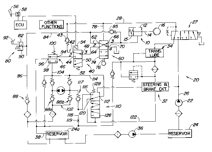
Brief Description of the Drawinqs
The sole figure is a schematic diagram of an
electrohydraulic control system for controlling the operation
of a spring-applied, pressure-released parking brake.

2086870
`~ Detailed Description
Referring to the figure, a spring-applied, pressure-
released parking brake 10 includes a release chamber 12 which
controls an actuator 14 which is engagable by spring 15 with
the output shaft 16 of the vehicle transmission (not shown).
An electrohydraulic parking brake control system 20 controls
operation of the parking brake 10 by controlling the
pressurization of the release chamber 12.
The control system 20 includes an engine driven pump 22
which supplies pressurized fluid from a reservoir or sump 24
to line 26, to the vehicle steering and brake circuit 32, to
the lube circuit 34, to pressure regulating valve 27 and to
line 28. A scavenger pump 36 transfers fluid collected from
various hydraulic functions in sump line 38 and sump 24a to
the sump 24. Thus, system pressure is communicated from pump
22 to line 28 and pressure regulating valve 27 with branches
to the steering and brake circuit 32 and the lube circuit 34.
A parking brake control valve 40 includes a housing
having an inlet 42 connected to line 28 via check valve 43, a
port 44 connected (when the vehicle is stopped) to the sump
line 38 via transport sump valve 46 and a port 48. Parking
brake control valve 40 also includes a parking brake valve
member 50 movable between a first position wherein the inlet
42 is communicated with the port 48 and the port 44 is
blocked, and a second position wherein inlet 42 is blocked and
port 44 is communicated with port 48. An energized solenoid
54 holds the valve member 50 in its first position. A spring
52 is biassed to move valve member 50 to its second position
when solenoid 54 is de-energized. The solenoid 54 is
operatively connected to a transmission shift lever 56 so that
the solenoid 54 will be energized when the shift lever 56 is
not a "park" position.
For example, if this invention were to be used in
connection with a transmission (not shown) controlled by a
microprocessor-based electronic control unit (ECU), then a
switch 58 or a transducer would sense when the shift lever 56
was not in its park position and provide an appropriate signal

- 2086~70
-to the ECU, which in turn would energize the parking brake
valve solenoid 54 via a convention valve driver circuit (not
shown).
A tow valve 60 includes a tow valve housing having a
first inlet 62, a second inlet 64 connected to port 48 of the
parking brake control valve 40, a first outlet 66 connected to
the release chamber 12 and a second outlet 70 connected to
reservoir pressure. Tow valve 60 also includes a tow valve
member 74 movable between a first position wherein the first
inlet 62 is communicated with the second outlet 70 and the
second inlet 64 is communicated with the first outlet 66, and
a second position wherein the first inlet 62 and the first
outlet 66 are blocked and the second inlet 64 is connected to
the second outlet 70. A member 76 is manually operable to
move the tow valve member 74 to either its first or its second
position. A pilot line 78 communicates pressurized fluid from
line 28 and acts to urge the valve member 74 toward its first
position.
An manually operated pump 80 includes a variable volume
chamber 82 which is communicated with the first inlet 62 of
the tow valve 60 via line 84 and with release chamber 12 via
check valve 85, and which is communicated with the sump 24a
via line 86 and check valve 88. Pump 80 also includes a
piston 90 which is operatively coupled to a manually operable
actuator 92, such as a foot operated vehicle clutch pedal.
The control system 20 also includes the transport sump
valve 46 which includes a housing having a port 94 connected
to port 44 of valve 40 and an outlet 96 connected to sump line
38. Valve 46 also includes a valve member 98 movable between
a first position wherein inlet 94 is communicated with the
outlet 96, and a second position wherein inlet 94 and outlet
96 are blocked. The valve member 98 is normally urged toward
its a first position by spring 100.
A conventional ground-driven pump/check valve assembly
102 receives fluid from reservoir 24a via check valve 88a or
88b and supplies fluid to pilot line 104 which acts on the
valve member 98 to urge valve member 98 to its second position.

2086S70
The manually operated pump 80 and the ground driven pump
102 draw their oil from a lower level in reservoir 24a than
does scavenger pump 36. This assures that the scavenger pump
36 will not draw reservoir 24a dry and prevents the ground
driven pump 102 and manually operated pump 80 from operating.
An emergency pump valve 110 includes a housing having an
inlet 112 which receives fluid from pump 102 via line 114, a
port 116 connected to pump assembly 102 via check valve 117
and to sump line 38 via line 118 and orifice 119, and a port
120 connected to steering and brake circuit 32 via pilot line
122. Valve 110 also includes a valve member 126 movable
between a first position wherein the inlet 112 is communicated
with the port 120 and port 116 is blocked, a second position
wherein inlet 112 is communicated with ports 116 and 120, and
a third position wherein inlet 112 is communicated with port
116 and port 120 is blocked. The valve member 126 is urged
toward its a first position by spring 128. The pilot line 122
communicates pressure from steering and brake circuit 32 to
the valve member 126 and this pressure urges the valve member
126 toward its second and third positions.
In the emergency steering mode (the first position of
valve 110), the oil flow from the ground driven pump 102 goes
to the steering circuit 32 and returns to reservoir 24a
through the transmission lube circuit, thereby providing a
closed loop in the circuit so that reservoir 24a will not be
pumped dry by the ground driven pump 102.
Mode of Operation
With the control system 20 in the condition illustrated
in Fig. 1, the solenoid 54 is energized, check valve 43 and
valves 40 and 60 communicate pressurized fluid from pump 22 to
the release chamber 12 and the parking brake 10 is released.
However, if the vehicle (not shown) is shut down and not
moving, then the solenoid 54 will be de-energized, valve 40
will move to its second position, the pressure will be
released from chamber 12 and the parking brake 10 will be
applied. This will be the case even if the operator forgets
or ignores putting the shift lever 58 in its park position.

2086870
-- If the shift lever 58 is moved to its park position and
the vehicle is stopped or below a predetermined speed, then
switch 56 will de-energize solenoid 54 and spring 52 moves
valve 40 to its second position thereby connecting release
chamber 12 to sump line 38 via valves 60, 40 and 46, and
allowing spring 15 to engage the parking brake 10. Thus, the
only effort required to engage the parking brake 12 is the
small effort required to move shift lever 58 to its park
position.
Inlet check valve 43 insures that the release chamber 12
will not be sumped through valves 76, 40 and line 28 in the
event of a failure in pump 22.
The transport sump valve 46 will prevent the park brake
from engaging if the vehicle is moving. The ground driven
pump 102 will provide a flow of oil to line 114 whenever the
vehicle is moving. The rate of flow is dependent of the speed
at which the vehicle is moving. In normal operation, that oil
goes through ports 112 and 116 of valve 110, the oil is then
recirculated to the ground driven pump through check valve 117
and to the sump line 38 through orifice 119. The orifice 119
and check valve 117 produce pressure in lines 114 and 104.
That pressure urges valve member 96 to position 2 where ports
94 and 96 are blocked thereby preventing oil flow from the
release chamber 12 through valves 60 and 40 to the sump line
38. The size of orifice 119 and pump 102 determine the
maximum speed at which the park brake can be engaged.
If it is desired to release the parking brake 12 while
the engine driven pump 22 is not operating (such as when
towing the vehicle), this can be accomplished by manually
moving tow valve 60 to its second position. This disconnects
the sump 24 from release chamber 12 and communicates release
chamber 12 with the manually operated pump 80. Actuation of
pedal 92 moves the piston 90 and transfers fluid from sump 24a
to the release chamber 12 via check valve 88, lines 86 and 84
and check valve 68. The parking brake 12 can be re-applied in
this situation merely by manually moving valve 60 back to its
first position. This disconnects pump 80 from chamber 12 and

2086870
communicates chamber 12 to the sump via valves 60, 40 and 46.
If the operator fails to reapply the parking brake 12 by
manually moving valve 60 back to its first position, the
parking brake 12 will be automatically applied when the engine
is started by oil pressure from pump 22 through line 26, 28,
78 and valve 27 moving valve 60 back to its first position
thereby sumping oil in the release chamber through valves 60,
40 and 46 to sump line 38.
While the invention has been described in conjunction
with a specific embodiment, it is to be understood that many
alternatives, modifications, and variations will be apparent
to those skilled in the art in light of the foregoing
description. Accordingly, this invention is intended to
embrace all such alternatives, modifications, and variations
which fall within the spirit and scope of the appending
claims.

Dessin représentatif
Une figure unique qui représente un dessin illustrant l'invention.
États administratifs

2024-08-01 : Dans le cadre de la transition vers les Brevets de nouvelle génération (BNG), la base de données sur les brevets canadiens (BDBC) contient désormais un Historique d'événement plus détaillé, qui reproduit le Journal des événements de notre nouvelle solution interne.

Veuillez noter que les événements débutant par « Inactive : » se réfèrent à des événements qui ne sont plus utilisés dans notre nouvelle solution interne.

Pour une meilleure compréhension de l'état de la demande ou brevet qui figure sur cette page, la rubrique Mise en garde , et les descriptions de Brevet , Historique d'événement , Taxes périodiques et Historique des paiements devraient être consultées.

Historique d'événement

Description Date
Le délai pour l'annulation est expiré 2007-01-08
Inactive : CIB de MCD 2006-03-11
Lettre envoyée 2006-01-09
Inactive : Renversement de l'état sera réputé périmé 2004-03-18
Lettre envoyée 2004-01-29
Lettre envoyée 2004-01-07
Accordé par délivrance 1996-07-30
Demande publiée (accessible au public) 1993-07-22
Toutes les exigences pour l'examen - jugée conforme 1993-01-07
Exigences pour une requête d'examen - jugée conforme 1993-01-07

Historique d'abandonnement

Il n'y a pas d'historique d'abandonnement

Historique des taxes

Type de taxes Anniversaire Échéance Date payée
TM (brevet, 5e anniv.) - générale 1998-01-07 1998-01-06
TM (brevet, 6e anniv.) - générale 1999-01-07 1999-01-06
TM (brevet, 7e anniv.) - générale 2000-01-07 2000-01-06
TM (brevet, 8e anniv.) - générale 2001-01-08 2001-01-05
TM (brevet, 9e anniv.) - générale 2002-01-07 2002-01-04
TM (brevet, 10e anniv.) - générale 2003-01-07 2003-01-06
TM (brevet, 11e anniv.) - générale 2004-01-07 2003-12-22
TM (brevet, 12e anniv.) - générale 2005-01-07 2004-01-06
Titulaires au dossier

Les titulaires actuels et antérieures au dossier sont affichés en ordre alphabétique.

Titulaires actuels au dossier
DEERE & COMPANY
Titulaires antérieures au dossier
DOUGLAS RENE JOHNSON
Les propriétaires antérieurs qui ne figurent pas dans la liste des « Propriétaires au dossier » apparaîtront dans d'autres documents au dossier.
Documents

Pour visionner les fichiers sélectionnés, entrer le code reCAPTCHA :


Pour visualiser une image, cliquer sur un lien dans la colonne description du document. Pour télécharger l'image (les images), cliquer l'une ou plusieurs cases à cocher dans la première colonne et ensuite cliquer sur le bouton "Télécharger sélection en format PDF (archive Zip)" ou le bouton "Télécharger sélection (en un fichier PDF fusionné)".

Liste des documents de brevet publiés et non publiés sur la BDBC .

Si vous avez des difficultés à accéder au contenu, veuillez communiquer avec le Centre de services à la clientèle au 1-866-997-1936, ou envoyer un courriel au Centre de service à la clientèle de l'OPIC.


Description du
Document 
Date
(aaaa-mm-jj) 
Nombre de pages   Taille de l'image (Ko) 
Revendications 1993-11-05 5 201
Abrégé 1993-11-05 1 22
Description 1993-11-05 8 382
Dessins 1993-11-05 1 32
Description 1996-07-29 8 388
Abrégé 1996-07-29 1 23
Dessins 1996-07-29 1 30
Revendications 1996-07-29 6 279
Dessin représentatif 1999-02-28 1 28
Avis concernant la taxe de maintien 2006-03-05 1 172
Correspondance 2004-01-28 1 7
Taxes 1997-01-05 1 68
Taxes 1996-01-04 1 51
Taxes 1995-01-05 1 56
Demande de l'examinateur 1995-08-21 2 58
Correspondance reliée au PCT 1996-05-21 1 32
Correspondance de la poursuite 1995-11-13 1 32
Correspondance de la poursuite 1993-06-28 1 32