Sélection de la langue

Search

Sommaire du brevet 2087049 

Énoncé de désistement de responsabilité concernant l'information provenant de tiers

Une partie des informations de ce site Web a été fournie par des sources externes. Le gouvernement du Canada n'assume aucune responsabilité concernant la précision, l'actualité ou la fiabilité des informations fournies par les sources externes. Les utilisateurs qui désirent employer cette information devraient consulter directement la source des informations. Le contenu fourni par les sources externes n'est pas assujetti aux exigences sur les langues officielles, la protection des renseignements personnels et l'accessibilité.

Disponibilité de l'Abrégé et des Revendications

L'apparition de différences dans le texte et l'image des Revendications et de l'Abrégé dépend du moment auquel le document est publié. Les textes des Revendications et de l'Abrégé sont affichés :

  • lorsque la demande peut être examinée par le public;
  • lorsque le brevet est émis (délivrance).
(12) Brevet: (11) CA 2087049
(54) Titre français: DISPOSITIF D'AJUSTEMENT POUR CEINTURE DE SECURITE
(54) Titre anglais: SEAT BELT ADJUSTER
Statut: Périmé et au-delà du délai pour l’annulation
Données bibliographiques
(51) Classification internationale des brevets (CIB):
  • B60R 22/20 (2006.01)
  • A44B 11/04 (2006.01)
  • B60R 22/02 (2006.01)
(72) Inventeurs :
  • CAMPBELL, TERRY A. (Canada)
(73) Titulaires :
  • TERRY A. CAMPBELL
  • MASTERLINK MARKETING INC.
(71) Demandeurs :
  • TERRY A. CAMPBELL (Canada)
  • MASTERLINK MARKETING INC. (Canada)
(74) Agent:
(74) Co-agent:
(45) Délivré: 2003-09-16
(22) Date de dépôt: 1993-01-11
(41) Mise à la disponibilité du public: 1993-11-28
Requête d'examen: 1999-08-31
Licence disponible: S.O.
Cédé au domaine public: S.O.
(25) Langue des documents déposés: Anglais

Traité de coopération en matière de brevets (PCT): Non

(30) Données de priorité de la demande:
Numéro de la demande Pays / territoire Date
07/889,559 (Etats-Unis d'Amérique) 1992-05-27

Abrégés

Abrégé anglais


A seat belt adjuster is provided for holding the lap
seat belt to the shoulder belt of an automobile seat belt
and prevent the shoulder belt rubbing against the neck of
a wearer. The adjuster is made of a single unitary piece
and therefore cannot be separated. A frame member formed
of resilient material has a front portion, rear portion,
top edge, bottom edge and space between the front and
back portions for containing the lap seat belt. There is
a hinge at the top edge joining the rear and front
portions together and a retaining snap at the bottom edge
to hold the two portions together. A clip forms part of
the front portion extending down from the top edge
retains the shoulder belt.

Revendications

Note : Les revendications sont présentées dans la langue officielle dans laquelle elles ont été soumises.


8
The embodiments of the present invention in which an
exclusive property or privilege is claimed are defined as
follows:
1. A seat belt adjuster for holding a shoulder belt
to a lap seat comprising:
a frame member formed of resilient material having a
front portion, a rear portion, a top edge, and a bottom
edge, the front portion and the rear portion forming a
channel therebetween for containing a lap seat belt;
a hinge extending from the top edge of the frame
member and pivotally coupling the rear portion and the
front portion together to permit the portions to open for
fitting over a lap seat belt;
means for retaining the rear portion and the front
portion together to contain a lap seat belt therebetween,
the retaining means being at the bottom edge of the frame
member;
a clip member forming part of the front portion of the
frame member and extending down from the top edge to form
an open clip for retaining a shoulder belt;
first and second pins coupled to the front portion of
the frame member adjacent the hinge, the first and second
pins being arranged to receive the rear portion
therebetween and to prevent a lap seat belt positioned
between the front and rear portions from contacting the
hinge; and
a third pin extending from one of the front and rear
portions, the other one of the front and rear portions
including a hole for receiving the third pin, the third
pin, when positioned in the hole, being between the first
and second pins and arranged to prevent a lap seat belt
positioned between the front and rear portions from
contacting the hinge.
2. The seat belt adjuster according to claim 1
wherein the front portion is wider than the rear portion.

9
3. The seat belt adjuster according to claim 2
wherein the hinge is a living hinge permitting the rear
portion to open up to about a 180° angle from the front
portion.
4. The seat belt adjuster according to claim 1
wherein the retaining means includes a hook member
positioned adjacent the bottom edge of the rear portion for
engagement in a slot formed in the front portion, the slot
having a ledge means so that the hook portion hooks over
and retains the rear portion to the front portion.

Description

Note : Les descriptions sont présentées dans la langue officielle dans laquelle elles ont été soumises.

2087049
47261-14
SEAT BELT ADJUSTER
The present invention relates to automobile seat
belts and more specifically to an adjuster for holding
together the lap seat belt and the shoulder belt at a
location where the shoulder belt does not rub against a
neck of a seat belt wearer.
Most seat belts used in vehicles, such as
automobiles, trucks, etc., have a lap seat belt which
extends across the lap of a wearer and also a shoulder
belt which extends up from the attachment side of the
belt, across the wearer's shoulder, thus providing
protection to the wearer from being thrown forward in the
event of a sudden stop. The lap seat belt holds the
wearer in the seat and the shoulder belt prevents the
wearer from jack-knifing forward. Most types of seat
belts are adjustable for different sized passengers and
drivers. A lap seat belt passes from one side of a seat
across the seat to a releasable catch or attachment
buckle on the other side of the seat. The belt passes
through the catch or attachment buckle and then becomes a
shoulder belt crossing over the front of a wearer and
being attached at shoulder height above the seat at the
side where the seat belt is initially attached.
The problem with such types of seat belts is that
the angle of the shoulder belt from the catch or
attachment buckle often extends across the neck of a
wearer and this can become irritating as it rubs against
the skin causing irritation. Devices have been made for
attaching to the lap seat belt and having a clip to hold
the shoulder belt. These devices slide along the lap
seat belt, thus moving the angle of the shoulder belt to
such a location where it does not rub against the neck of

. /"",
. 20 8709
2
a wearer. One example of such a device is shown in U. S .
Patent 5,088,161 to Robertson.
The device disclosed in U.A. Patent 5,088,161 is
formed of two parts and when it is to be removed from a
seat belt, requires one part to be detached from another.
This invariably results in one of the parts dropping and
becoming lost. under the seat of a vehicle or even dropping
outside the vehicle, thus one is left with only one part
which by itself is useless.
The present invention provides a novel seat belt
adjuster which is a one piece unit having in one embodiment
a hinge at one end and in another embodiment having a
series of slats with gaps allowing the seat blet adjuster
to be attached to the lap seat belt and detached from it
but remaining in one piece so that the parts do not become
separated.
The present invention provides a seat belt adjuster
for holding a shoulder belt to a lap seat comprising:
a frame member formed of resilient material having a
front portion, a rear portion, a top edge, and a bottom
edge, the front portion and the rear portion forming a
channel therebetween for containing a lap seat belt;
a hinge extending from the top edge of the frame
member and pivotally coupling the rear portion and the
front portion together to permit the portions to open for
fitting over a lap seat belt;
means far retaining the rear portion and the front
portion together to contain a lap seat belt therebetween,
the retaining means being at the bottom edge of the frame
member;
a clip member forming part of the front portion of the
frame member and extending down from the top edge to form
an open clip for retaining a shoulder belt;
first and second pins coupled to the front portion of
the frame member adjacent the hinge, the first and second
A'

. ~ . 2087049
3
pins being arranged to receive the rear portion
therebetween and to prevent a lap seat belt positioned
between the front and rear portions from contacting the
hinge; and
a third pin extending from one of the front and rear
portions, the other one of the front and rear portions
including a hole for receiving the third pin, the third
pin, when positioned in the hole, being between the first
and second pins and arranged to prevent a lap seat belt
positioned between the front and rear portions from
contacting the hinge.
In drawings which illustrate embodiments of the
present invention,
Figure 1 is a diagrammatic view of a driver or
passenger sitting on a seat in a vehicle with a seat belt
such as the type described in the present invention in
place to redirect the shoulder belt away from the neck of
the driver or passenger.
x, ~
r

~os7o~~
- 4 -
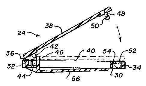
Figure 2 is an elevational view showing one
embodiment of a seat belt adjuster in the open position
ready for attachment to a lap seat belt.
Figure 3 is a sectional view taken at line 3-3 of
Figure 2 showing the seat belt adjuster partially open
with the closed position shown in dotted lines.
Figure 4 is a front elevational view showing another
embodiment of a seat belt adjuster.
Figure 5 is an end view of the seat belt adjuster
shown in Figure 4.
Figure 6 is a perspective view of another embodiment
of a seat belt adjuster according to the present
invention.
A seat belt arrangement 10 is shown in Figure 1
representative of the prior art for a passenger or driver
12 in a seat 14 within a vehicle 16. The seat belt 10
extends from a retracting mechanism 18 which is
permanently attached to the side of the vehicle 16 below
the seat 14 and has a lap seat belt 20 extending over to
an attachment buckle 22. The belt is looped through the
attachment buckle 22 and then passes to a seat belt
adjuster 24 from where the shoulder belt 26 passes up
over the shoulder of the wearer 12 to an attachment loop
28 at the side of the vehicle 16 above the retracting
mechanism 18. The belt passes from the attachment loop
28 down to the retracting mechanism 18. It is the seat
belt adjuster 24 which is the subject of the present
application. The purpose of the seat belt adjuster 24 is
to move the bottom location where the shoulder belt 26
departs from the lap seat belt 20, so that the belt does
not rub against the neck of a wearer.

208709
- 5 -
One embodiment of a seat belt adjuster 24 is shown
in Figures 2 and 3 which comprises a fixed frame member
30 or front portion which is actually hollow at its
centre and has a top edge 32 and a bottom edge 34. At
the top edge 32 a living hinge 36, which is integrally
molded, and connects the front portion 30 to a rear
portion being a flap 38. The flap 38 is rectangular in
shape and folds down as shown in Figure 3 from a
completely open position as shown in Figure 2 to a closed
position to provide a space 40 for holding a lap seat
belt 20. The flap 38 has a pin 42 spaced from the hinge
36 which engages into an aperture 44 in the front portion
34. The pin 42 acts as a stop to prevent the belt from
being pushed up on the flap 38 and preventing the hinge
36 from closing. Furthermore, on each side of the front
portion 34 there are two further pegs 46 which extend up
on either side of the flap 38 when it is in place. These
two further pegs 46 also act as stops to prevent the belt
from being forced into the hinge 36.
At the other end of the flap 38 is a hook member 48
having a hook 50. The hook member 48 fits into a cutout
slot 52 at the other end of the front portion 34. The
slot 52 has a shoulder 54 which engages the hook 50 when
the hook member 48 is pushed into the slot 52.
On the front of the front portion 34 is a clip
member 56 integral with the front portion 34 and attached
adjacent the top edge 32. The clip member 56 is provided
to permit the shoulder belt 26 to be held to the lap seat
belt 20 at a desired location to prevent the shoulder
belt 26 from rubbing against the neck of a wearer 12.
As can be seen, to attach the seat belt adjuster 24
to a lap seat belt 20, it is necessary to first open the
flap 38 by releasing the hook member 48 from the slot 52,
pivoting open the flap 38 back, placing the lap seat belt

207049
- 6 -
20 into the space 40 adjacent the front portion 34, then
pivoting closed the flap 38 about the hinge 36 and
snapping it into place by means of the hook member 48.
The shoulder belt 26 is then hooked under the flap 56.
The adjuster 24 may be moved along the lap seat belt 20
to a desired location to ensure that the shoulder belt 26
does not rub against the neck of a wearer.
Figures 4 and 5 illustrate another embodiment of the
invention which is made from resilient material such as
plastic. In another embodiment the adjuster 24 may be
made from resilient metal or other suitable material.
Unlike the embodiment shown in Figures 2 and 3, the seat
belt adjuster 24 of Figures 4 and 5 does not have a
living hinge 36 as shown in Figures 2 and 3, but has a
rigid hinge at the top edge 32 thus relying on the
flexibility of the material to provide the hinge
movement. The rear portion or flap 38 extends for the
full length of the front portion 30 and has a hook end 60
arranged to snap over a tapered shoulder 62 which is part
of the front portion 30. Thus the rear portion 38 and
the front portion 30 are held together by the hook 60
engaging the step 62. A space 40 is left therebetween
for the lap seat belt 20 to pass through.
The resilient material, which is preferably a hard
plastic, permits the front portion 30 and rear portion 38
to be opened and the hook 60 is released from the step
62. The two portions are forced apart relying more on
the flexibility of the material rather than on the hinge
at the top edge 32, however, there is some flexibility in
this top edge portion and for the purposes of the present
application, it is defined as a rigid hinge. The space
between the two portions 30,38 is sufficient to
contain the lap seat belt 20 and permit it to be slid
along the belt 20 to the preferred position.

2087049
_7_
As in the case of the seat belt adjuster shown in
Figures 2 and 3 the clip member 56 is provided for
clipping the shoulder belt 26 and guiding the shoulder
belt to miss the neck of the wearer.
Another embodiment is shown in Figure 6 which is a
one piece arrangement of adjuster 24 having a generally
rectangular frame which a central raised portion 70 and
two side flanges 72 which extend from the top edge 32 to
the bottom edge 34. The side flanges 72 have
longitudinal slots 74 cut therein and the slots 74 have
gaps 76 open to the edges of the flanges 72 thus
permitting insertion of the lap seat belt 20 to fit into
the slot 74 through the gaps 76. The clip member 56 is
provided in the same manner as that shown in the other
Figures for supporting the shoulder belt 26. The clip
member 56 extends from the central raised member 70
adjacent the top edge 32.
All three of the seat belt adjusters shown in the
drawings are integral units formed from one piece. The
material of construction is preferably a resilient
plastic of sufficient strength to grip the seat belt but
not meant in any way to prevent the operation of the seat
belt during an abrupt stop of a vehicle.
Various changes may be made to the embodiments shown
herein without departing from the scope of the present
invention which is limited only by the following claians.

Dessin représentatif
Une figure unique qui représente un dessin illustrant l'invention.
États administratifs

2024-08-01 : Dans le cadre de la transition vers les Brevets de nouvelle génération (BNG), la base de données sur les brevets canadiens (BDBC) contient désormais un Historique d'événement plus détaillé, qui reproduit le Journal des événements de notre nouvelle solution interne.

Veuillez noter que les événements débutant par « Inactive : » se réfèrent à des événements qui ne sont plus utilisés dans notre nouvelle solution interne.

Pour une meilleure compréhension de l'état de la demande ou brevet qui figure sur cette page, la rubrique Mise en garde , et les descriptions de Brevet , Historique d'événement , Taxes périodiques et Historique des paiements devraient être consultées.

Historique d'événement

Description Date
Le délai pour l'annulation est expiré 2013-01-11
Lettre envoyée 2012-01-11
Inactive : TME en retard traitée 2009-03-04
Lettre envoyée 2009-01-12
Inactive : CIB de MCD 2006-03-11
Accordé par délivrance 2003-09-16
Inactive : Page couverture publiée 2003-09-15
Préoctroi 2003-06-16
Inactive : Taxe finale reçue 2003-06-16
Un avis d'acceptation est envoyé 2003-01-13
Lettre envoyée 2003-01-13
Un avis d'acceptation est envoyé 2003-01-13
Inactive : Approuvée aux fins d'acceptation (AFA) 2003-01-02
Lettre envoyée 2002-06-12
Exigences relatives à la révocation de la nomination d'un agent - jugée conforme 2002-06-11
Inactive : Lettre officielle 2002-06-11
Demande visant la révocation de la nomination d'un agent 2002-05-30
Exigences de rétablissement - réputé conforme pour tous les motifs d'abandon 2002-05-30
Inactive : Lettre officielle 2002-03-25
Lettre envoyée 2002-03-25
Inactive : Transfert individuel 2002-02-20
Lettre envoyée 2002-02-12
Inactive : Lettre officielle 2002-01-30
Réputée abandonnée - omission de répondre à un avis sur les taxes pour le maintien en état 2002-01-11
Inactive : Transfert individuel 2002-01-11
Inactive : Renseign. sur l'état - Complets dès date d'ent. journ. 1999-09-15
Lettre envoyée 1999-09-15
Inactive : Dem. traitée sur TS dès date d'ent. journal 1999-09-15
Toutes les exigences pour l'examen - jugée conforme 1999-08-31
Exigences pour une requête d'examen - jugée conforme 1999-08-31
Demande publiée (accessible au public) 1993-11-28
Déclaration du statut de petite entité jugée conforme 1993-01-11

Historique d'abandonnement

Date d'abandonnement Raison Date de rétablissement
2002-01-11

Taxes périodiques

Le dernier paiement a été reçu le 2002-10-28

Avis : Si le paiement en totalité n'a pas été reçu au plus tard à la date indiquée, une taxe supplémentaire peut être imposée, soit une des taxes suivantes :

  • taxe de rétablissement ;
  • taxe pour paiement en souffrance ; ou
  • taxe additionnelle pour le renversement d'une péremption réputée.

Veuillez vous référer à la page web des taxes sur les brevets de l'OPIC pour voir tous les montants actuels des taxes.

Historique des taxes

Type de taxes Anniversaire Échéance Date payée
TM (demande, 5e anniv.) - petite 05 1998-01-20 1998-01-12
TM (demande, 6e anniv.) - petite 06 1999-01-11 1998-10-19
Requête d'examen - petite 1999-08-31
TM (demande, 7e anniv.) - petite 07 2000-01-11 2000-01-06
TM (demande, 8e anniv.) - petite 08 2001-01-11 2000-10-30
Enregistrement d'un document 2002-01-11
TM (demande, 9e anniv.) - petite 09 2002-01-11 2002-01-11
Rétablissement 2002-05-30
TM (demande, 10e anniv.) - petite 10 2003-01-13 2002-10-28
Taxe finale - petite 2003-06-16
TM (brevet, 11e anniv.) - petite 2004-01-12 2003-10-28
TM (brevet, 13e anniv.) - petite 2006-01-11 2003-10-28
TM (brevet, 12e anniv.) - petite 2005-01-11 2003-10-28
TM (brevet, 14e anniv.) - petite 2007-01-11 2003-10-28
TM (brevet, 15e anniv.) - petite 2008-01-11 2007-11-29
TM (brevet, 16e anniv.) - petite 2009-01-12 2009-03-04
Annulation de la péremption réputée 2009-01-12 2009-03-04
TM (brevet, 17e anniv.) - petite 2010-01-11 2009-06-04
TM (brevet, 18e anniv.) - petite 2011-01-11 2010-10-21
Titulaires au dossier

Les titulaires actuels et antérieures au dossier sont affichés en ordre alphabétique.

Titulaires actuels au dossier
TERRY A. CAMPBELL
MASTERLINK MARKETING INC.
Titulaires antérieures au dossier
S.O.
Les propriétaires antérieurs qui ne figurent pas dans la liste des « Propriétaires au dossier » apparaîtront dans d'autres documents au dossier.
Documents

Pour visionner les fichiers sélectionnés, entrer le code reCAPTCHA :


Pour visualiser une image, cliquer sur un lien dans la colonne description du document. Pour télécharger l'image (les images), cliquer l'une ou plusieurs cases à cocher dans la première colonne et ensuite cliquer sur le bouton "Télécharger sélection en format PDF (archive Zip)" ou le bouton "Télécharger sélection (en un fichier PDF fusionné)".

Liste des documents de brevet publiés et non publiés sur la BDBC .

Si vous avez des difficultés à accéder au contenu, veuillez communiquer avec le Centre de services à la clientèle au 1-866-997-1936, ou envoyer un courriel au Centre de service à la clientèle de l'OPIC.


Description du
Document 
Date
(aaaa-mm-jj) 
Nombre de pages   Taille de l'image (Ko) 
Dessin représentatif 1999-03-29 1 12
Dessin représentatif 2003-01-03 1 9
Page couverture 2003-08-13 1 37
Abrégé 1994-03-13 1 16
Page couverture 1994-03-13 1 11
Revendications 1994-03-13 3 80
Dessins 1994-03-13 2 35
Description 1994-03-13 7 244
Description 1999-10-04 7 291
Revendications 1999-10-04 2 60
Rappel - requête d'examen 1999-09-14 1 127
Accusé de réception de la requête d'examen 1999-09-15 1 193
Courtoisie - Lettre d'abandon (taxe de maintien en état) 2002-02-11 1 182
Courtoisie - Certificat d'enregistrement (document(s) connexe(s)) 2002-03-25 1 113
Avis de retablissement 2002-06-12 1 172
Avis de rappel: Taxes de maintien 2002-10-15 1 118
Avis du commissaire - Demande jugée acceptable 2003-01-13 1 160
Avis de rappel: Taxes de maintien 2003-10-15 1 114
Avis de rappel: Taxes de maintien 2007-10-15 1 130
Avis de rappel: Taxes de maintien 2008-10-15 1 120
Avis concernant la taxe de maintien 2009-02-23 1 171
Quittance d'un paiement en retard 2009-03-24 1 163
Avis de rappel: Taxes de maintien 2010-10-13 1 121
Avis de rappel: Taxes de maintien 2011-10-12 1 120
Avis concernant la taxe de maintien 2012-02-22 1 170
Deuxième avis de rappel: taxes de maintien 2012-07-12 1 127
Correspondance 2002-01-30 1 29
Correspondance 2002-03-25 1 12
Correspondance 2002-02-12 3 150
Correspondance 2002-05-30 1 73
Correspondance 2002-06-11 1 15
Correspondance 2002-06-11 1 18
Correspondance 2003-06-16 1 58
Taxes 2003-10-28 1 111
Taxes 1998-01-12 1 45
Taxes 2002-05-30 1 65
Taxes 2002-10-28 1 71
Taxes 2007-11-29 1 44
Taxes 2009-03-04 1 103
Taxes 2009-06-04 1 56
Taxes 2010-10-21 1 49
Taxes 1996-11-05 1 54
Taxes 1994-12-20 1 34
Taxes 1995-12-14 1 31