Sélection de la langue

Search

Sommaire du brevet 2087148 

Énoncé de désistement de responsabilité concernant l'information provenant de tiers

Une partie des informations de ce site Web a été fournie par des sources externes. Le gouvernement du Canada n'assume aucune responsabilité concernant la précision, l'actualité ou la fiabilité des informations fournies par les sources externes. Les utilisateurs qui désirent employer cette information devraient consulter directement la source des informations. Le contenu fourni par les sources externes n'est pas assujetti aux exigences sur les langues officielles, la protection des renseignements personnels et l'accessibilité.

Disponibilité de l'Abrégé et des Revendications

L'apparition de différences dans le texte et l'image des Revendications et de l'Abrégé dépend du moment auquel le document est publié. Les textes des Revendications et de l'Abrégé sont affichés :

  • lorsque la demande peut être examinée par le public;
  • lorsque le brevet est émis (délivrance).
(12) Brevet: (11) CA 2087148
(54) Titre français: FREIN A DISQUE
(54) Titre anglais: DISK BRAKE
Statut: Périmé et au-delà du délai pour l’annulation
Données bibliographiques
(51) Classification internationale des brevets (CIB):
  • F16D 65/18 (2006.01)
  • F16D 55/00 (2006.01)
  • F16D 65/14 (2006.01)
(72) Inventeurs :
  • ITSUAKI, SATORU (Japon)
(73) Titulaires :
  • SUMITOMO ELECTRIC INDUSTRIES, LTD.
(71) Demandeurs :
(74) Agent: SMART & BIGGAR LP
(74) Co-agent:
(45) Délivré: 1996-07-02
(22) Date de dépôt: 1993-01-12
(41) Mise à la disponibilité du public: 1993-07-14
Requête d'examen: 1993-05-10
Licence disponible: S.O.
Cédé au domaine public: S.O.
(25) Langue des documents déposés: Anglais

Traité de coopération en matière de brevets (PCT): Non

(30) Données de priorité de la demande:
Numéro de la demande Pays / territoire Date
4-4016 (Japon) 1992-01-13

Abrégés

Abrégé anglais


A disk brake has a brake piston for biasing pads
against a disk. The piston is arranged so that the center
of its biasing force is offset toward the disk leading side
from the center of frictional surface of the pad. Also,
the piston is arranged so that the center of biasing force
is offset toward the center of the disk from the line
extending in the tangential direction of the disk and
passing the center of frictional surface of the pad. In
another arrangement, a disk brake has a plurality of brake
pistons adapted to bias each pad. One of the brake pistons
located at the disk leading side has a greater pressure
bearing area than that of the other brake piston at the
disk trailing side. The brake pistons are arranged so that
the center of biasing force is offset toward the center of
the disk from the line extending in the tangential
direction of the disk and passing the center of frictional
surface of the pad.

Revendications

Note : Les revendications sont présentées dans la langue officielle dans laquelle elles ont été soumises.


The embodiments of the invention in which an exclusive
property or privilege is claimed are defined as follows.
1. A disk brake, comprising:
a brake pad having first and second frictional surfaces
thereon, each said frictional surface having a center;
a disk having a center and a leading side and a trailing
side relative to said brake pad, wherein each said center of
said first and second frictional surfaces is located on a
respective radius of said disk, one said radius being located
on a leading side of said brake pad and the other said radius
being located toward a trailing side of said brake pad; and
a pair of brake pistons for biasing said brake pad
against said disk, said pair of brake pistons comprising a
first brake piston located toward the leading side of said
brake pad and a second brake piston located toward the
trailing side of said brake pad, wherein said first brake
piston has a greater pressure bearing area than said second
brake piston, wherein said first brake piston provides a
biasing force centered on a location on said brake pad that is
between said center of said disk and a line passing through
said center of said first frictional surface and perpendicular
to the one said radius, and wherein said second brake piston
provides a biasing force centered on a location on said brake
pad that is between said center of said disk and a line

passing through said center of said second frictional surface
and perpendicular to the other said radius;
wherein said locations of the centered biasing
forces of said first and second brake pistons are disposed on
the one said radius and the other said radius, respectively.
2. The disk brake of claim 1, wherein said pressure bearing
areas of said first and second brake pistons are centered on
the respective said locations on said brake pad.
3. The disk brake of claim 1, wherein said first and second
brake pistons have the same amount of fluid pressure applied
thereto.

Description

Note : Les descriptions sont présentées dans la langue officielle dans laquelle elles ont été soumises.

2û87148
DIS'~ B~AKE
This invention relates to a disk brake having pads
which are less liable to uneven abrasion.
An ordinary disk brake comprises a disk and friction
members adapted to be urged by a hydraulic brake piston
into frictional contact with the disk. The piston is
arranged so that the center of its biasing force is
located on the line extending in a tangential direction of
the disk and passing the center of frictional surface of
the pad or offset therefrom toward the outer periphery of
tne disk to increase the breaking force with a larger
effective braking radius. If the friction member of each
pad comprises a plurality of segments, the respective
segments have individual centers of frictional surface.
In such a disk brake, in order to reduce uneven
abrasion of the pads at the disk trailing side due to
angular moment that acts on the pads when braking, the
brake piston is arranged so that the center of its biasing
force is offset toward the disk leading side from the
center of frictional surface of the pad. With a brake in
which each pad is urged by a plurality of pistons receiving
the same fluid pressure, the piston at the disc leading
side is adapted to have a larger pressure bearing area than
the piston at the trailing side in order to smooth out the
,~

20871 48
dlstrlbutlon of surface pressure on the pad in a tangential
direction.
With a disk brake having no means for preventing uneven
abrasion, lf the brake piston ls lncllned ln the tangentlal
dlrectlon of the dlsk and becomes stuck ln a cyllnder due to
uneven abraslon of the pad in the tangential direction of the
dlsk, lt becomes dlfflcult for the plston to lncllne ln the
radlal dlrectlon of the dlsk ln the cylinder. Thus, uneven
abrasion of the pad in the diametric direction of the disk
will not develop any further.
In contrast, with the above-described disk brake provided
with means for preventing uneven abraslon, the plston can
lncllne more freely in the cylinder in the diametric direction
of the disk than the former piston. A conventional disk brake
of this type has its piston arranged so that the center of its
biasing force is located on the line extending on a tangential
directlon of the disk (in a direction perpendicular to a
diametric direction) and passing the center of frictional
surface of the pad or offset therefrom toward the outer
periphery of the dlsk. Thus, the surface pressure on the pad

2 0 8 7 ~ ~ 8 ~
wlll be distrlbuted uniformly in a tangential direction of the
pad or will be stronger at its portion near the outer
perlphery of the disk. Due to these factors and also to the
difference ln revolving speeds between inner and outer parts
of the disk, the pad tends to be abraded more rapidly in its
portion near the outer perlphery of the dlsk. Thus, as a
whole, the pad ls abraded unevenly to a conslderable degree ln
a dlametrlc dlrection of the dlsk.
It ls therefore an ob~ect of the present lnventlon to
reduce uneven abraslon of the pad both ln tangentlal and
dlametrlc direction of the disk.
Accordlng to the present invention, there ls provlded a
disk brake, comprlslng a brake pad havlng flrst and second
frlctlonal surfaces thereon, each sald frlctlonal surface
havlng a center; a dlsk havlng a center and a leadlng slde and
a tralllng slde relatlve to sald brake pad, wherein each sald
center of said flrst and second frlctional surfaces is located
on a respective radlus of sald dlsk, one sald radius being
located on a leading side of sald brake pad and the other sald
radlus belng located toward a tralllng slde of sald brake pad;

-
208 7 1 48
and a pair of brake pistons for biasing said brake pad against
said disk, said palr of brake pistons comprising a first brake
piston located toward the leading side of said brake pad and a
second brake piston located toward the trailing side of said
brake pad, whereln sald flrst brake plston has a greater
pressure bearing area than said second brake piston, wherein
said first brake piston provides a biasing force centered on a
locatlon on said brake pad that ls between said center of said
dlsk and a line passing through said center of sald first
frictional surface and perpendlcular to the one said radlus,
and wherein said second brake piston provides a biasing force
centered on a location on said brake pad that is between said
center of sald dlsk and a llne passlng through said center of
sald second frlctlonal surface and perpendlcular to the other
sald radlus; whereln sald locatlons of the centered biasing
forces of said first and second brake pistons are disposed on
the one said radius and the other said radius, respectively.
By arranging the piston so that the center of its
biasing force is offset toward the center of the disk from
the line extending in a tangential direction of the disk and
passing the center of frictional surface of the pad,
3a
.

2~871~
the surface pressure applied to each pad is greater at its
inner peripheral portion than at its outer peripheral
portion. The work done per unit area and unit hour is
defined by ~surface pressure) x (peripheral speed) ~
(friction coefficient). Since the surface pressure of the
pad is greater at its inner peripheral part while the
peripheral speed is smaller at the inner peripheral part,
the difference in the amount of work done between the inner
and outer peripheral parts resulting from the difference in
peripheral speed is offset by the difference in surface
pressure. Thus, according to the present invention, the
difference in the amount of work between the inner and
outer peripheral parts of the pad is small compared with a
conventional brake. This reduces uneven abrasion of the
pad in a diametric direction of the disk.
The present invention has solved the problem that the
pad tends to be abraded unevenly in a diametric direction.
Thus, change in pedal stroke resulting from uneven abrasion
of the pad can be reduced to a minimum. The pad has a
longer life. Squeaking of the brake can be reduced.
Further, since the braking energy is absorbed
uniformly over the entire frictional surface of the pad,
the brake works stably even under high-load braking
conditions. Thus, the braking performance improves still
further.

20 87 1 4~
Other features and objects of the present invention will
become apparent from the following description made with
reference to the accompanying drawings, in which:
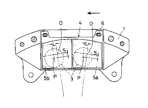
Fig. 1 is a front view of one embodiment of the disk brake
according to the present invention with the outer side of the
caliper removed;
Fig. 2 is a front view of another embodiment showing the
said condition as in Fig. 1;
Fig. 3 is a front view of still another embodiment showing
the same state as in Fig. 1; and
Fig. 4 is a diagrammatic view showing in exaggeration the
brake piston inclined due to uneven abrasion of the pad in a
tangential direction of the disk.
Figure 4 shows a disc brake having no means for preventing
uneven abrasion of the pad 4 in which the pad is more severely
abraded at the disc trailing side 4b than at the disc leading
side 4a.
Referring to Fig. 1, in an embodiment of the present
invention, a brake piston 3 is mounted in a cylinder of a
caliper 1. A pad 4 is supported by pad pins 6 so as to be
slidable in an axial direction of the disk. In this
embodiment, the pad 4 comprises an integrally formed single
lining 5. Thus, the centre O of the frictional surface of the
pad 4 is located at the intersection of the centre lines of the
single lining 5 with respect to a peripheral direction and a
diametric direction of the disk. The piston 3 for the brake is
arranged so that center P of its biasing force is offset a
distance L toward the disk leading side (left-hand side in the

2`0871 48
figure) from the center O of the frictional surface of the pad
and also offset a distance S toward the center of the disk from
the line extending in a tangential direction of the disk and
passing the center O. With this arrangement, uneven abrasion
of the pad can be reduced not only in a tangential direction of
the disk but in its diametric direction.
Fig. 2 shows another embodiment in which two brake pistons
3 having the same diameter (and thus the same pressure bearing
surface) are used to bias a single pad 4. In this case, the
pad 4 comprises two lining segments 5a, 5b. The respective
segments have individual centers O of frictional surface. Each
piston 3 is arranged so that the center P of its biasing force
is offset a distance L toward the disk leading side (left-hand
side in the figure) from the center O of the frictional surface
of the respective pad 4 and also offset a distance S toward the
center of the disk from the line extending in a tangential
direction of the disk and passing the respective center O.
Fig. 3 shows still another embodiment in which two brake
pistons 3, 13 having different diameters are used to urge a
single pad 4. One of the pistons that is located at the disk
leading side (left-hand side in the figure) has a greater
diameter and thus a greater pressure bearing surface than the
other. Since the two pistons have different diameters, uneven
abrasion of the pad in a tangential direction of the disk can
be reduced to a considerable degree. Thus, in this
~';.,

2087148
embodiment, there is no need to arrange the pistons so that
their respective centers P of biasing force are offset
toward the d-isk leading side from the respective centers 0.
The centers P are only offset toward the center of the disk
from the respective centers O of frictional surface.

Dessin représentatif
Une figure unique qui représente un dessin illustrant l'invention.
États administratifs

2024-08-01 : Dans le cadre de la transition vers les Brevets de nouvelle génération (BNG), la base de données sur les brevets canadiens (BDBC) contient désormais un Historique d'événement plus détaillé, qui reproduit le Journal des événements de notre nouvelle solution interne.

Veuillez noter que les événements débutant par « Inactive : » se réfèrent à des événements qui ne sont plus utilisés dans notre nouvelle solution interne.

Pour une meilleure compréhension de l'état de la demande ou brevet qui figure sur cette page, la rubrique Mise en garde , et les descriptions de Brevet , Historique d'événement , Taxes périodiques et Historique des paiements devraient être consultées.

Historique d'événement

Description Date
Inactive : CIB désactivée 2012-01-07
Inactive : Symbole CIB 1re pos de SCB 2012-01-01
Inactive : CIB du SCB 2012-01-01
Inactive : CIB expirée 2012-01-01
Le délai pour l'annulation est expiré 2009-01-12
Lettre envoyée 2008-01-14
Inactive : CIB de MCD 2006-03-11
Accordé par délivrance 1996-07-02
Demande publiée (accessible au public) 1993-07-14
Toutes les exigences pour l'examen - jugée conforme 1993-05-10
Exigences pour une requête d'examen - jugée conforme 1993-05-10

Historique d'abandonnement

Il n'y a pas d'historique d'abandonnement

Taxes périodiques

Le dernier paiement a été reçu le 

Avis : Si le paiement en totalité n'a pas été reçu au plus tard à la date indiquée, une taxe supplémentaire peut être imposée, soit une des taxes suivantes :

  • taxe de rétablissement ;
  • taxe pour paiement en souffrance ; ou
  • taxe additionnelle pour le renversement d'une péremption réputée.

Veuillez vous référer à la page web des taxes sur les brevets de l'OPIC pour voir tous les montants actuels des taxes.

Historique des taxes

Type de taxes Anniversaire Échéance Date payée
TM (brevet, 5e anniv.) - générale 1998-01-20 1997-12-17
TM (brevet, 6e anniv.) - générale 1999-01-12 1998-12-16
TM (brevet, 7e anniv.) - générale 2000-01-12 1999-12-09
TM (brevet, 8e anniv.) - générale 2001-01-12 2000-12-20
TM (brevet, 9e anniv.) - générale 2002-01-14 2001-12-19
TM (brevet, 10e anniv.) - générale 2003-01-13 2002-12-18
TM (brevet, 11e anniv.) - générale 2004-01-12 2003-12-17
TM (brevet, 12e anniv.) - générale 2005-01-12 2004-12-07
TM (brevet, 13e anniv.) - générale 2006-01-12 2005-12-07
TM (brevet, 14e anniv.) - générale 2007-01-12 2006-12-08
TM (demande, 2e anniv.) - générale 02 1995-01-12
Titulaires au dossier

Les titulaires actuels et antérieures au dossier sont affichés en ordre alphabétique.

Titulaires actuels au dossier
SUMITOMO ELECTRIC INDUSTRIES, LTD.
Titulaires antérieures au dossier
SATORU ITSUAKI
Les propriétaires antérieurs qui ne figurent pas dans la liste des « Propriétaires au dossier » apparaîtront dans d'autres documents au dossier.
Documents

Pour visionner les fichiers sélectionnés, entrer le code reCAPTCHA :


Pour visualiser une image, cliquer sur un lien dans la colonne description du document. Pour télécharger l'image (les images), cliquer l'une ou plusieurs cases à cocher dans la première colonne et ensuite cliquer sur le bouton "Télécharger sélection en format PDF (archive Zip)" ou le bouton "Télécharger sélection (en un fichier PDF fusionné)".

Liste des documents de brevet publiés et non publiés sur la BDBC .

Si vous avez des difficultés à accéder au contenu, veuillez communiquer avec le Centre de services à la clientèle au 1-866-997-1936, ou envoyer un courriel au Centre de service à la clientèle de l'OPIC.


Description du
Document 
Date
(aaaa-mm-jj) 
Nombre de pages   Taille de l'image (Ko) 
Page couverture 1993-11-06 1 15
Abrégé 1993-11-06 1 24
Dessins 1993-11-06 2 42
Revendications 1993-11-06 1 30
Description 1996-07-02 8 247
Revendications 1996-07-02 2 53
Dessins 1996-07-02 2 36
Description 1993-11-06 7 211
Page couverture 1996-07-02 1 13
Abrégé 1996-07-02 1 27
Dessin représentatif 1999-06-21 1 10
Avis concernant la taxe de maintien 2008-02-25 1 174
Taxes 1996-12-19 1 78
Taxes 1996-01-12 1 50
Taxes 1994-12-07 1 56
Correspondance de la poursuite 1995-09-27 2 65
Correspondance reliée au PCT 1993-08-19 1 48
Demande de l'examinateur 1995-06-02 2 55
Correspondance de la poursuite 1995-03-22 3 128
Courtoisie - Lettre du bureau 1993-08-16 1 35
Correspondance de la poursuite 1993-05-10 1 41
Correspondance reliée au PCT 1996-04-24 1 47
Courtoisie - Lettre du bureau 1996-04-15 1 52
Correspondance de la poursuite 1996-03-29 4 108