Note : Les descriptions sont présentées dans la langue officielle dans laquelle elles ont été soumises.
2 ' '! ` f3 r l
TITLE OF_THE INVENTION
Method and de~ice for operating a synchronous machine
BACKGROUND OF THE INVENTION
Field of the invention
The invention is based on a method and a device
for operating a synchronous machine in accordance with
the preamble of claLms 1 and 2.
Discussion of Backqround
In the preambles of claLms 1 and 2, the
invention refers to a background which is known from
the ASEA Journal 1976, Vol. 4, pages 75 80. In this
journal, a static frequency converter, the link voltage
of which is used for exciting the rotor windings, is
used for starting pump turbine units with synchronous
machines. Above a frequency of 5 Hz, the system
switches from self-commutation with resonant-circuit
control to load-controlled commutation with the aid of
the voltage generated by the motor. At about 15~ of the
rated speed, the water is pushed down in the pump
turbine so that the runner rotates in air during the
remaining run-up. The plant is provided with an
integrated protection device for detecting and
signalling internal disturbances such as overvoltages
and ground faults. There is an electronic pulse
inhibitor as protection against overcurrents.
German Offenlegungs~chrift 21 10 747 discloses
a comparable background for starting gas turbines or
pumped-storage units.
There is no provision for redundantly using the
static converters of the frequency converters in a
fault case.
Additional reference relating to the relevant
background is made to the house ~ournal of the Swiss
firm BBC Brown, Boveri & Company, Baden, publication
No.: CH-E 2 . 0340 . 0 E, title. Standardized Starting
Equipment, January 1979, pages 1 - 8, from which it is
known to start synchronous machines, which can be used,
- 2 - ~ ~ 8,3~7
for example, in conjunction with gas turbines, pumped--
storage plants and synchronous compencators, by mean~
of a static frequency converter.
SUMMARY OF THE INVENTION
The invention as defined in claLms 1 and 2
achieves the ob~ect of developing a method and a device
for operating a synchronous machine of the type
initially mentioned in such a manner that its
reliability is increased.
An advantage of the invention consists in that
the redundant use of the static converter of the
frequency converter results in greater availability of
the plant.
The run-up and excitation device for the
synchronous machine can also be used in conjunction
with gas turbines.
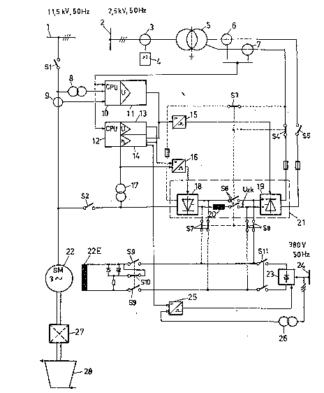
BRIEF DE5CRIPTION OF THE DRAWINGS
A more complete appreciation of the invention
and many of the attendant advantages thereof will be
readily obtained as the same becomes better understood
by reference to the following detailed description when
considered in conjunction with the accompanying single
figure, where a run-up and excitation device for a
synchronous machine which is coupled to a gas turbine
is shown.
DESCRIPTION OF THE PREFERRED ~IODIMENTS
A synchronous machine (22) is connected at its
stator end, on the one hand via a current transformer
(9) and a switch (Sl) to a three-phase system or
alternating-current sy~tem (1) having an alternating
voltage of 11. 5 kV and a frequency of 50 Hz and, on the
other hand, via a switch (S2) to a frequency converter
(21). The frequency converter (21) exhibits two
conkrollable static converters (18, 19) which are
connected to one another via a direct-current link
comprising a link reactor (20) and a dual switch (S6).
`
- 3 - ~,v~ i3 ~ ~
A link direct voltags (Uzk) can be applied to an
exciter winding (22E) of the synchronous machine (22)
via closed dual switches (S8) and (S9) when the dual
switch (S6) is opened. When the dual switch (S6) is
closed and the dual switch (S8) iR open, the link
direct voltage (Uzk) can be applied to the exciter
winding (22E) via a dual switch (S7) as indicated with
dashed lines.
The static converter tl9) is connected via
fuses, switches (S4, S5) and current transformere (6,
7) to a secondary winding of a static converter
transformer (5) which i~ connected on the primary side
via a current transformer (3) to a three-phase
auxiliary system or alternating-current system (2) with
an alternating voltage of 2.5 kV and a frequency of
50 Hz. (4) designates a protective relay which is
connected to the current transformer (3) and switches
-off with a predeterminable overcurrent.
The current transformers (6, 7) supply current
signals to microprocessors or high-speed computers (10,
12). The high-speed computer (10) receives at its input
end a further current signal from the current
transformer (9) and a line voltage signal from a
voltage transformer (8), the input side of which is
connected to the rotor winding of the synchronous
machine (22). At its output end, the high-speed
computer (10) is connected via an automatic voltage
regulator (11) to a firing-pulse transformer (15) which
supplies firing signals to the static converter (19).
The high-speed computer (12) is connected at its output
end to a manually operable voltage regulator (13) and
to a load-commutatable or start-up regulator (14). The
start-up regulator (14) acts at its output end on the
firing pulse transformer (15) and on a further firing
pulse transformer (16) which supplieR on its output
side firing signals to the static converter (18). The
firing pulse transformer (16) additionally receives on
its input side an output signal of the voltage
regulator (13) and a voltage signal from a voltage
~ r~ f) ~ rf
_ 4 -
transformer (17) which i8 connected to the rotor of the
synchronous machine (22) via the switch (S2) and also
provides its output signal to the start-up regulator
(143.
Right at the start of the run-up, the exciter
winding (22E) of the synchronous machine (22) is fed
with direct current from a tarting converter (23) via
closed dual switches (S9) and (Sll). The starting
converter (23) receives its power from a start exciter
current source (24) with an alternating voltage 380 V
and a frequency of 50 Hz; it is fired from a firing
pulse transformer (25). The firing pulse transformer
(25) receives a control signal from the start-up
regulator (14) and from a voltage transformer (26)
which is connected to the start exciter current source
(24). (S10) designates a switch which is closed when
the dual switch (S9) is open and which i~ open when the
dual switch (S9) is closed. A switch (S3) is connected,
on the one hand, to the switch (S4) and, on the other
hand, via a fuse to the alternating-current input of
the static converter (18), compare the da~hed line. All
switches connected by dashed lines are opened when the
associated switches, not connected by dashed lines, are
closed, and conversely.
The synchronous machine (22) is drive-connected
at its rotor end to a gas turbine (28) via a
transmis~ion (27). The transmission (27) can also be
omitted. The gas turbine (28) can be fed by combustion
ga~e~ from a diesel engine or from a special combustion
chamber and possibly interact with one or with a number
of steam turbines.
It is important that the exciter direct voltage
for the exciter winding (22E) is taken from the direct-
current link of the frequency converter (21) when the
~ynchronous machine (22) is line~operated.
The synchronous machine (22) is run up with an
opened switch (S1) and closed switch (S2) by the static
converter (18) which is operated as inverter with
,
i~ {~
increa~ing frequency and is fed from the direct-current
link.
When the rated speed of the synchronous machine
(22) ha~ been reached, the switch (S2) i8 opened and
the switch (Sl) is closed.
The additional feeding of the static converter
(18) via the switch (S3~, however, allows a 2-channel
excitation in the subsequent continuous operation of
the synchronous machine (22). If, for example, the
static converter (19) fails due to a fault during the
continuous operation, the static converter (18) can be
connected to the alternating-current system (2) via the
switch (S3) and can be operated as rectifier in order
to generate the direct current required for the
excitation of the exciter winding (22E). If, for
example, the static convertex (18) fails due to a
fault, the static converter (19) can supply the
required direct current for the exciter winding t22E).
Naturally, the alternating-current systems (1)
and (2) and ~e start exciter current source (24) can
be operated with other alternating voltages than those
specified and, for example, with 60 Hz. The static
converter transformer (S) could also be connected to
the alternating-current system (1).
Obviously, numerous modifications and
variations of the present invention are possible in the
light of the above teachings. It i8 therefore to be
under~tood that within the scope of the appended
claims, the invention may be practised otherwise than
as specifically described herein.