Note : Les descriptions sont présentées dans la langue officielle dans laquelle elles ont été soumises.
n 2p88792 ~v
COATING OF A ROLL IN A PAPER MACHINE
USING HYPERSONIC PLASMA
The invention is concerned with a method of
coating of a roll'of a paper machine with powder of
thermo-plastic specialty plastic and the roll made with
the method.
Coating rolls are used for very different purposes
in paper machines and in posthandling machines for
paper. Among the applications can for example, the
following be mentioned: press rolls, suction rolls,
soft rolls in calenders and super calenders and the
like. Different quality requirements are set for the
coating of the roll in different applications and in
different processes. Conventional quality factors for
the coating are, for example, the hardness in a given
temperature, temperature resistance, press resistance,
chemical resistance, surface smoothness, resistance
against mechanical damages, elasticity, surface energy,
release properties of the paper, conductivity and non-
aging.
Conventionally, rolls of paper machines have been
coated with rubber, polyurethane or epoxy. These
polymeric materials are especially suitable for coating
of large rolls of manufacturing technical reasons.
One- or two-component polyurethane and epoxy are
available in fluid form in which case the casting of
those in a form or rotation casting is possible. It is
also very easy to mix these polymeric materials with
different fillers and additives to achieve new
properties for the coating material. In addition to
the form and rotating casting, suitable manufacturing
techniques (coating techniques) for the polyurethane
and epoxy include extrusion, spraying, filament
B
2 2088792
winding, tape winding, spun casting and different
impregnated mats.
Epoxy (a thermo-setting plastic) and polyurethane
(a thermo-setting plastic or an elastomer) are
materials which are used as roll coatings because, in
addition to manufacturing and technical advantages,
such polymers have advantageous properties.
Polyurethane has good dynamic and abrasion properties
and epoxy has been providing corrosion properties. The
properties of the epoxy has retained also in higher
temperatures.
The use of thermo-plastics as roll coatings has
mainly been restricted by the loss of the advantageous
properties with increasing coating temperatures and by
manufacturing problems (expressly with respect to
coating of large rolls).
A strong development has, however, occurred during
the last 10 years with respect to thermo-plastics. In
Figure 1 a classification of actual thermo-plastics
have been presented generally.
30
B~
2088792 w
2a
In the following Table 1 there is a list according
to ISO 1043-1 of abbreviations and names for some
S polymers. It also includes possible homopolymers.
D
2088'~9~
3
Table 1.
CA Cullulose-acetate
CAB Cellulose acetate butyrate
CN Cellulose nitrate
CP Cellulose propionate
EP Epoxy or epoxide
MF Melamine formaldehyde
PA Polyamide (quality is expressed with
numbers)
PAI Polyamide-imide
1o PAN Polyacrylnitrile
PB Polybutene-1
PBT Polybutene terephtalate
PC Polycarbonate
PCTFE Polychlorotrifluorethene
PDAP Polydiallyl phthalate
PE Polyethene
PEI Polyether-imide
PEK Polyetherketone
PEEK+ deri-
2o vatives Polyetheretherketone
PES Polyethersulfon
PET Polyethenterephtalate
PF Phenol formaldehyde
PFA Perfluoroalcoxyalkane
PI Poly-imide
PIB Polyisobutene
PMI Polymetakryl-imide
PMMA Polymethylmethacrylate
PMP Poly-4-methylpentene-1
3o POM Polyoxymethene or polyacetal
PP Polypropene
PPE Polyphenylenether, earlier polyphenylen
oxide PPO
PPS Polyphenylen sulfide
PS Polystyrene
PSU Polysulfone
PTEE Polytetrafluoroethene
PUR Polyurethane
PVC Polyvinyl chloride
PVDC Polyvinyliden chloride
4o PVDF Polyvinyliden fluoride
PVF Polyvinylfluoride
SI Silicon
OF Ureaformaldehyde
UP Unsaturated polyester
2088792
4
The group of speciality plastics are especially interesting. Typical
properties
for plastics belonging to this group are good temperature resistances
(260°C),
good mechanical properties, the retaining of the properties even in high tem-
peratures, in spite of high tensile strengths and good hardness properties,
retained elasticity and a low impregnation of water. In table 2 there has been
presented properties of the speciality plastic PEEKK as a function of the tem-
perature.
TABLE 2
to Temperature
property -40C 23C 80C 120C 150C 220C Unit
Tensile 129 108 76 56 49 - N/mm2
strength
Ultimate 4 6 6,5 9 10 - %
elongation
Tear strength109 86 69 55 48 35 N/mm2
Tear elonga-30 28 100 124 128 142 %
tion
Tensile-E- 4150 4000 3490 3340 3100 230 N/mm2
2o Modulus
Bending 131 120 107 91 84 8 N/mm2
stress
Bending-E- 3860 3640 3370 3120 3010 240 N/mm2
Modulus
Notch impact9 9 mJ/mm2
toughness
( Charpy)
2088792
The advantageous properties of the specialty
plastics at high temperatures are based on the
substitution of the conventional aliphatic bond with an
aromatic bond.
The specialty plastics afford properties which are
suitable for roll coatings, for example, in paper
machines, board machines and paper refineries. They
can be used either reinforced or not.
The specialty plastics are, however, thermo
plastics and their processing methods are typical for
thermo-plastics. Specialty plastics are available in
granulates from which such fabricates as films, discs,
tubes and bars are manufactured by injection moulding
and extrusion.
Thermo-plastics are also available in powder form
in which case possible manufacturing techniques are
dispersion spraying, electrostatic powder spraying,
fluidized bed coating, flame spraying, plasma spraying
and rotomolding.
Filament winding and tape winding are typically
suitable manufacturing techniques for thermo-plastics,
but recently the use of these two techniques has been
more common also for thermo-plastics. Thermo-plastics
and also specialty plastics can thus be obtained in
powder form.
Large rolls can be coated with plastic powder by:
1. Electrostatic spraying, but only relatively thin
coatings. The porosity of the coatings is high and in
the case of specialty plastics the preheating and
postheating temperatures of the roll body are high
which is not advantageous with respect to the paper
machine rolls (carton and paper ref).
2. Fluidized bed coatina, but as in the case of the
electrostatic spraying, only thin coatings of a high
~~.~
6
2088792 -y
porosity. The preheating/postheating temperatures of
the roll bodies are high. Manufacturing problems are
associated with this method.
3. Dispersion spraying, in which technique the plastic
powder is in the form of a dispersion in some suitable
solvent. The dispersion is sprayed onto a surface of a
body. The solvent evaporates/is evaporated away such
that a very thin coating film is left on the surface of
the working piece which often requires further
temperature treating. Another possibility is to mix
the plastic powder among some one- or two-component
polymer. When the one- or two-component polymer
reacts, a matrix is formed in which the plastic powder
is left .
4. Rotormoldina technique, which is meant to coat
interior surfaces, why it cannot be used for coating of
outer surfaces of rolls.
5. Flame spraying, the problems of which is presented
in the following.
Only standard plastics (for example PE, EVA, PP)
can in some extent be sprayed without preheating of the
piece. These plastics do not, however, suit for
technically requiring roll coatings.
In connection with flame spraying with a specialty
plastic, the working piece must be heated to a
temperature as high as possible when thick coatings are
wished. The temperature can, however, not exceed a
given threshold in which the plastic burns. Also, the
roll construction can set a limit for the temperature.
Working pieces with thin walls need a higher preheating
temperature than compact pieces. It is especially
difficult to flame spray pieces of different
thicknesses.
~B
6a
The plastic coating is sprayed in layers. The
effect of the preheating decreases considerably after
the first spraying layer. The piece has cooled down as
the temperature has not been tried to keep. Even if
the temperature would be tried to keep, the coating to
be formed becomes an isolate when becoming thicker.
Because of the differences in the cooling rates, the
temperature differences have increased. The first
plastic layer isolates the heat coming from the working
piece which limits the coating thickness.
In a too thick coating and in a plastic coating
with lacking heat energy in the outer layer, the melt
drops separate, whereat its construction becomes worse,
the inner strength weak and the crystallization degree
wrong .
2p 887 9 2
Similar difficulties appear also in connection with the conventional plasma
spraying. In conventional plasma spraying the heat effect of the spraying is
formed
so that the electric energy forms an arc between the wolfram cathode and the
annular copper anode. A gas or a gas mixture is led to the arc which is
strongly
heated up and the gas molecules are disintegrated to atoms and the atoms
further
to ions and electrons. The gas has converted to a plasma. Thus the electric
energy
has transmitted to the gas (to the plasma) and raised its inner energy. This
inner
energy is utilized in the melting of plastic powders so that the powder is fed
to the
out streaming plasma (figure 2) wherein it is plasticized. The plasma spray
accel-
to erates the melt drops with a high rate on the surface of the piece to be
coated.
The temperature of the plasma spray is very high; 7000 - 15000°C. Due
to the high
temperature the thermal radiation of the plasma is very high. There is
obtained
some advantages from this radiation energy in the melting of plastic powders
as it
increases the temperature of the working piece which is advantageous with
respect
to the polymerization and thus with respect to the forming of the coating.
The drawback with the conventional plasma spraying is that the temperature of
the
plasma flame is too high with respect to the plastic, and the plastic tends to
oxidize. Further disadvantages with the conventional plasma spray is the low
flowing rate of the gas and that the heat effect of the flame is too low to
keep the
compact pieces warm. Generally the plastics of table 3 is sprayed with conven-
tional plasma; in other words not speciality plastics.
8
2088792 ~'
TABLE 3
A COMPARISON OF USUAL POWDERY COAT TYPES OF COATINGS
THERMO THEIL'~t0
SETTING PLASTICS
PLASTICS
Epoxy PolyesterPolyesterHybrideAcryl Nylon PVC
urethaneTGIC
I
Application/120-1~?150-200140-300140-220140-200180-320170-290
curing
tempera-
ture C
Thickness < 1-12 < 1-3,0< 1-4,0< 1-4,0< 1-3,04-12 10-20
of
the 61m
(1)
Hardness HB-SH HB-SH HB-SH H-2H 2H-SH
Outer strength- + + - + + 0
Weather - + + - + + -
strength
QLJV-strength+ 0 0 - + 0 0
I Solvent + 0 0 0 0 + -
S strength
Chemical + + + + + + +
strength
Impact + + + + 0 + +
strength
(1) Normal thickness range - Much more thicker films
20 can be used with some materials.
The meanings of the signs:
+ Generally preferable/acceptable
0 Sometimes preferable/acceptable
- Generally not preferable/acceptable
25 The present invention is directed towards the
preparation of more resistant coatings having the
desired property or properties at the same time and to
the provision of a method that overcomes the drawbacks
of prior art so that a coating that is thick enough can
30 be prepared also of specialty plastics.
The method of the invention to achieve the aims is
mainly characterized in that the coating is carried out
with spraying by using hypersonic plasma.
2088792
Accordingly, in one aspect of the present
invention, there is provided a method for coating a
roll of a paper machine with a powder comprising a
thermo-plastic specialty plastic, comprising providing
a plasma spray system in which a plasma flame having a
hypersonic velocity of 2000 m/s or more is formed,
directing the plasma flame toward a surface of a roll
to be coated, and introducing a powder comprising
particles of a thermo-plastic specialty plastics into
the hypersonic plasma flame to form a coating on the
surface of the roll.
The present invention includes, in another aspect
thereof, a coated roll for use in a paper machine, the
roll having an outer coating comprising a thermo-
plastic specialty plastic powder which has been applied
by means of a hypersonic plasma spray.
The difference between the hypersonic device
(Figures 3 and 4) and a conventional gas plasma
apparatus affords some advantages which can be utilized
in accordance with the invention in spraying plastic
powders.
Thus, hypersonic plasma is used according to the
invention in the spraying of powders of specialty
plastics, whereat the high effect of the plasma device
of, for example, Figure 3 is utilized in is different
forms (200 kW, plasma flame, radiation heat,
convection). The preheating temperature of the working
piece is tried to keep so low that the coating plastic
does not burn (depends on the plastic) but in spite of
that thick layers of 200 ~m - 100 ~m can be sprayed.
Even thick coatings can get the correct crystallization
degree in the invention, whereat optimal properties of
the plastic are achieved even in thick coatings. The
granule sizes of the powders to be sprayed are in the
9a
range of 20 ~m - 1000 Vim. The rolls to be coated can
be variable crown compensated rolls, suction rolls,
center rolls and rolls of super calenders and soft
calenders.
The melt particles of the hypersonic plasma spray
produce coatings of good quality with a large
proportion having a high density, good adhesion, a
smooth and sprayed surface wherein very little
disintegration occurs. The particles that are moving
with an oversonic rate produce very dense and non-
porous coatings, partly also in a non-melt state.
A given procedure must be followed to produce a
hypersonic plasma spray. Plasma sprays can in some
extent be achieved with a high rate with a conventional
spray by increasing the gas stream and by using a
smaller diameter in the nozzle. However, if the rate
of the plasma is increased, it should be noted that the
retention time of the powder is shortened at the same
time and the heat content
,_
2088792
io
shall also be increased to melt the powder. Then a higher effect must be used,
mainly by increasing the arc flow, as a very high potential, over 100 V,
cannot be
achieved with a conventional plasma spray. Ca 80 kW is the threshold of the
high
effect to be used in a conventional plasma apparatus. Hypersonic plasma must
be
used for a higher effect.
Very high gas streams (even 30 m3) are used in high effect plasma sprays of
the
invention used in figure 3, whereat the rate of the out streaming gas
increases up
to 2000 m/s. The temperature of the plasma flame decreases to ca 6000°C
due to
to the higher flow rate of the gas. Thus, as the exposure temperature and
exposure
time are lower, less damaging oxidation of the plastic particles occur in the
high
effect plasma spray than in an conventional plasma spray. Due to the higher
gas
flow rate, the cathode and the anode are at a bigger distance from each other,
whereat the potential between the cathode and the anode increases to ca 300-
450
volt (when it is in a conventional plasma spray is some 10 volts). Due to a
higher
potential, the heat energy of the flame can be increased up to 250 kW (when it
in
a conventional spray is some tens kW). This high heat energy can effectively
be
used to heat up massive pieces.
2o The heat from the plasma flame radiates in all directions but the radiation
can be
lead onto the surface of the working piece by different cooled mirrors to be
placed
beyond and at the side of the flame in the same way as in the situation in
which
the light is reflected by a cup in lamps.
2s Furthermore, the heat effect of the flame can be regulated by means of
gases used
so that the increase of the flowing rate can raise the heat effect. The heat
effect
can be further raised by use of hydrogen and helium. The heat effect can be
decreased in a corresponding way by means of argon.
3o In the method the body can be preheated, if desired, but this is not often
so
necessary or desirable.
It is also possible to use a new plasma spraying system that uses atmospheric
~48~~9~
plasma to produce hypersonic plasma which has double anodes for example
according to figure 4.
The driving costs can be decreased with this system to less than 50% of those
s which are caused by conventional systems, even if conventionally used
materials
are in question. Thin films of materials with a high melting point can also be
made, as Zr02, with this system that sprays atmospheric plasma as with a con-
ventional system that sprays plasma of low pressure. When it is question of
cermet
as WC-CU, a very abrasion resistant film can be made which is as good as that
to made with the above mentioned hypersonic plasma device.
The double anodes of the device can be heated by effectively feeding the
materials
to be sprayed directly in the flame centre of the plasma arc and the spraying
pattern can be made more narrow. Therefore the efficiency of the plasma
spraying
15 can be improved so that it is better than in conventional systems.
Thus the invention can be used for preparing also thick coatings by using
speciality
plastics and so to achieve optimal properties for the coating.
2o Especially the properties of the coating can be regulated in the thickness
direction
of the coating or in the direction of the roll axle. For example the
elasticity
modulus can be regulated by regulating the porosity of the coating between the
layers. If a smaller elasticity modulus is wished the heat introduction is
decreased.
The module of elasticity of the coating can be regulated also in the direction
of
25 the roll axle, for example, in the ends of the roll there can be a
different module
of elasticity compared with the central region.
The regulation possibilities of the heat introduction
- preheating of the roll
30 - regulation of the flame
by regulation of the electric effect
by regulation of the amount of the gas
by regulation of gas proportions
12 2088792 -'
by reflection of the flame
by using outer extra heaters (for example IR and
induction
For example in the journal KONEPAJAMIES number 3,
1991 usable specialty plastics for the invention have
been presented (see Figure 1, page 2).
For example the following kinds of rolls of board
and paper machines and paper finishing machines are
coated with a coating of the invention: guide rolls,
suction rolls, press rolls, center rolls, cylinders,
calender rolls, cutting machine rolls and so on.
The usability of the method of the invention is
improved in that coatings of the method of the
preparation can be modified by commonly known methods
of consolidation of engineering plastics, for example,
a so-called Whiskers fibre reinforcing (the Whiskers
fibre is a very little individual crystal fibre) or
winding of a continuous fibre (Filament Winding).
Especially the use of the filament winding method
enables an effective raise of the peripherential
strength of the coating which has special importance
when the intention is to achieve higher nip loads.
Further advantages of the method of the invention
are that simultaneously with the specialty plastic, for
example, metal, ceram or cermet particles can be
sprayed. Herewith the properties of the coating can
influence, for example, the abrasion strength. Then
the feeding place of the particles in question to the
plasma must be chosen so that they are coming to the
right place on the basis of their melting temperature.
The problem with the polymer materials is in some
cases that the humidity tends to diffuse due to the
thermal diffusion from the warmer roll surface to the
colder body. This means that special requirements are
t
2088792
13
set for the body with respect to the corrosion
resistance. The roll body can be effectively taken care
of with the method of the invention so that a metallic
S corrosion resistant layer is sprayed with the same spray
as also the polymeric coating before the polymeric layer.
In this respect a hypersonic spraying affords a superior
advantage compared with conventional methods as the
coating becomes very compact and corrosion resistant due
to the high rate of the flame. Naturally some other
layer, an epoxy adhesion layer, can be used as substrate
layer.
Coating materials of the invention have been
presented in Figure 1, and the thickness of the coating
is preferably in the range of 200 ~m - 10 mm.
In the following description, the method of the
invention is presented by means of Figures which are not
meant to restrict the invention, wherein:
Figure 1 shows a classification of thermoplastics;
Figure 2 presents a conventional plasma spray;
Figure 3 presents a function principle of a high
effect plasma spray usable in the method of the
invention; and
Figure 4 presents the principle of a spraying system
that uses an atmospheric plasma to be used in the method
of the invention which contains a double anode.
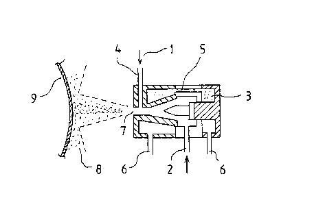
In Figure 2 that presents a conventional plasma
spray, the feeding of the powder takes place at 1 and the
feeding of the gas at position 2. The wolfram cathode is
marked with the reference number 3 and the copper anode
with the reference number 4. The part that has been
marked with the reference number 5 is an intermediate
isolation and number 6 are electrical and valve
connections. The plasma spray comes out from
D
14 2088792
position 7 and is sprayed in form of melt particles 8
over the substrate 9.
The construction of the high effect plasma spray
has been presented in Figure 3. The arc is transferred
from the electrode (-) far into the cylindrical nozzle
(+), but the gas stream forces it to the center of the
nozzle and it proceeds out of the nozzle and returns to
the surface of the output. When the arc extends over
125 mm it uses a very high potential 500 volt and
produces an oversonic high energy plasma spray. An
extended plasma arc is well parallellized and retains
in a concentrated form to long distances from the
nozzle.
The theory of the extensive plasma arc is the
following. The high stream of the plasma arc, mainly
nitrogen, is fed from the electrode through the gas
distributor far to the cylindrical nozzle that makes a
very strong vortex. A very high DC-potential, 600
volt, of the open circuit is used between the nozzle
(-) and the electrode (+). The high frequency ignites
the spray and the arc transfers from the electrode to
the nozzle but a strong gas stream forces it to its
center and it extends far out from the nozzle and
returns to its outer surface because there are no other
passages. A very long arc, over 100 mm, raises the
potential very high, up to 400 volt, and effectively
heats the plasma gas to produce a very hot hypersonic
plasma spray. As a very high potential is easily
achieved for the arc with these sprays that produce a
very extensive plasma arc, the stream of the arc can be
set low to be able to sue a very high effect in the
spray .
The hypersonic plasma device designed by Jim
Browning consists of only five components which are a
B
14a
water-cooled electrode (-) with gas distribution holes,
a water-cooled cylindrical nozzle (+) and an isolated
space, a front frame for the spray and an isolated back
frame. Cooling water is led in from position 11 and
out from position 12. The plasma spray is marked with
the reference number 7' and the extended arc with
number 13 and the impact diamond with number 14.
The plasma spray is very controlled and centered
even a long distance from the surface of the nozzle.
The plasma spray, for example, of wolfram carbide
particles, proceeds straight more than one meter and is
very concentrated at this distance. It looks like a
plasma flame in low pressure. More than 700 of the fed
electric effect is given to the high gas stream and the
rate of the plasma spray becomes oversonic at values
over 3000 m/s and is observed through protection
glasses with impact diamonds 14.
A powder 1' is fed from the output of the nozzle
directly to the very hot and extended arc. An addition
of hydrogen to the plasma gas further raises the heat
energy. Typically values of the energy used are
208~'~~2
- electric effect 200 kW (400 V x 500 A)
- gas stream ca 230 SLM (500 SCFH)
- output enthalpy 35 x 106 J/kg /15.000 BTU/Lb)
- plasma temperature 6000°C
5 - spray rate 3000 m/sek
For the details of the device reference is furthermore made to the article
"Coatings
by 250 kW Plasma Jet Spray System" T. MORISHITA, Plazjet Ltd, Tokyo, Japan.
(Source: Proceedings of 2nd Plasma Tec. Symphosium, June 5-7, 1991, Vol. lp-
l0 137).
The construction of the device spraying atmospheric plasma that comprises a
double anode is presented in figure 4. To stabilize the anode place of the arc
the
device is foreseen with one cathode jet 15 and two anode jets 16 so that the
anode
15 jets are symmetrically arranged as is presented in figure 4. The cathode
place and
the anode place are protected with inert gas as Ar 17 or N2. In this system
the arc
is not instable in any way which could lead to abrasion of the anode place or
migration of the anode place or abrasion of the electrodes, whereas such an
instability is a problem in conventional systems. Thus the spraying conditions
can
be retained stable for a long time. The accelerating nozzle 18 can be loosened
and
its diameter and length are set in forehand to be appropriate for the plasma
spraying. In other words the rate and temperature of the plasma can be
regulated
by varying the diameter length and effect. This nozzle corresponds. to the
wearing
part of conventional jets. But it does not touch the arc directly and
generally there
is no need to change it. As is presented in figure 4, the plasma arc 19
consists of
a cathode arc on the axle of the cathode jet and anode arc on the axle of the
anode jet.
A strong cold housing is formed around each arc flame and it increases the
3o direction of the arc and the concentration of the heat. Such a stable
condition is
retained even if the main arc exceeds the sonic speed. The plasma gas that
forms
the main arc is fed from a place outside the chamber wherein the cathode is
pro-
tected with inert gas 17 as is presented in figure 4 and with air 20. The rate
and
16 2088792 r
enthalpy of the plasma gas can as a result of this be
extensively regulated with the effect of 10 - 100 kW.
The plasma spray produced is presented with the
reference number 7" that is sprayed as particles 8" on
a substrate 9" and coating 21. The device is
preferably also foreseen with a plasma cleaning device
22 to maintain a good quality.
The direct current circuits of the device have
also been marked in the Figure (D.C. ) . The main feed
of the effect takes place in a bigger circuit. For the
part of the device reference is furthermore made to the
article A. BUNYA etc. "New Plasma Spraying System Twin
Torch a" (Source NTSC 91/Pittsburg).
~i.