Note : Les descriptions sont présentées dans la langue officielle dans laquelle elles ont été soumises.
WO92/03319 2 0 g g ~ 0 8 PCT/US91/04~3
--1--
REGULATOR SUPPLY VAI.VE FOR ADAPTIVE
BRAKING A~D TR~CTION CONTROL S~STEMS
The present inven~ion relates g~nerally to a
regulator supply va~ve for adaptive braking and traction
control systems, a~d in particular to a supply valve
which integrates both adaptive braki~g and tra~tion con-
trol regulated pressurè supply functaons.
~ umerous adaptive brakîng and traction controlsystems have been provided previously. It is advanta-
geous to provid~ a combination adaptive brakiny an~ trac
tion co~trol system which can be implemented in a vehiole
as an add-on feature to the standard braking system. The
adaptive bra~ing and traction control syst~m must be
compatible with a standard ~aster cylinder, while provid-
ing both adaptive braking and traction control ~unc-
tions. Some accumulator supplied adaptiYe braking sys-
tems require that a regulator valve meter the high pres-
sure a~cumulator supply provided to the brakes through
the modulator valves during cycling. Th~ regulator keeps
the supply pressure equal to the applied master cylinder
pressure. 5' Some :traction control systems also require a
supply valve to meter the accumulator pressure supplied
to the modulators during traction control cycling. Such
.a ualYe typically provides a high pressure level without
a master cylinder pressure bei~ applied to the valve.
It ma~ be desirable to;limit ~his traction control pres-
25 ..sure.to a set maximum l~vel. ;It would be hiyhly advanta-
geous to .combine both the adaptive.braking and traction
.contxoI .systems and.the~related~supply ualves so that
both ~unctions could be provided by the Same valve. .This
.. .~can lead to ~reduced components and complexity for the
!' ;" ~ 30 system, whi}e reducing~ the -internal circuits of the
. hydraulic assembly.~
The present invention provides a soIution to the
abuve problems by pro~i~ding :an adaptivè braking syst~m
..~ with traction control, comprising master cylinder means
.35 ha~ing reseruoir~;means-~and ~communicating with at least
:
,
: ~ - . . ........... . . . ............ .. . . .
~,. ~ . ~, . . , : ,
W092~033~9 : , PCT/U5~1/0~3
2 0 8 8 ~
-- 2 --
one wheel brake of the vehicle via modulator means, pres-
sure source means communicating with said reservoir, and
a regulator supply valve communicating with said pressure
source means, modulator means, and master cylinder means,
wherein during adaptive braking system operation pressure
from a chamber of said master cylinder causes said regu-
lator supply valve to communicate pressure from said
pressure source means to said modulator means, and during
traction control operation the regulator supply valve is
1o activated by said control means to communicate said pres-
sure source m~a~s with said modulator means.
One way of carrying out the inve~tion is
described in detail with reference to the drawin~s which ~.
illustrate embodiments in which:
Figure 1 is a schematic illustration of an adap-
tive braking and traction control system with regulator
supply valve of the present invention;
Figure 2 is a section view of a reyulator supply
valve of the present inventi~n;
Figure 3 is a section view of an alternative
. ,regulator supply valve of the present invention;
.-. . Figure 4 is a section view of another alterna-
tive regula~or supply valYe of.the present invention;
Figure 5 -is a section view of a third alterna-
~25 tive embodiment of the regulator supply valve;
Figure 6 .is a section view o~ a regulator supplyvalve~or a braking.system~having.only traction control;
Figure 7 is a section:view of ~nother regulator
supply -valve:~or.ai.braking system.having only traction
` 310 control;:and ~- ,;:. ~ ....
.. ~ m~ ;.Figure .8 is an .illustration o~ a selected por-
tion~ of :an adaptive braking and traction control system
containing a traction control æupply valve integral with
an end o~a boosted master~cylinder.
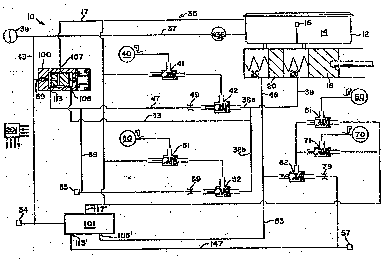
Figure 1 is :a:-schematic representation of an
~adaptive braking and traction -control :system identi~ied
general}y by re~erence numeral 10. System 10 includes
:
, .. . . . . . .
WO92/03319 2 0 ~ g 9 ~ ~ PCT/US91/0~3
master cylinder 12 which ineludes r~ser~oir 14 with fluid
level switch 16, primary piston 1~ and secondary piston
20, primary pressure chamber 28 and secondary pressure
chamber 30, with primary pressure chamber 28 communicating
via lines 38 and 38a with right fro~t wheel brake 40 and
via lines 38 and 38b with let front wheel brake 50, and
secondary pressure chamber 30 communicating ~ia line 48
with right rear wheel brake 60 and left sear wheel brake
70. The system includes for right front wheel brake 40
an electrically operated decay valve 41 and eleetrically
operated isolation and build valve 42. ~eft ~ront wheel
brake 50 includes associated decay valve 51 and isolation
and build valve 5~. Right rear wheel brake 60 includes
associated decay valve 61 and rear isolation and build
vsl~re 62. Likewise, left rear wheel brake 70 includes
associated decay valve 71 and rear isolation and build
valve 6Z. The sets of decay and isolation and build
valves each comprise means for modulating fluid pressure
to the respective wheel brake. Pressure source 35 com-
prises pump 36 and an accumulator 39, the pump receivingfluid from reservoir 14 and co~municating it via line 37
with accumulator 39 and via line 43 with an accumulator
switch or transducer 54:and a pair of regulator supply
val~es 100 and 101.: Regulator supply valves 100 and 101
are identical and contain the same inlet and outlet ports
in relation to the respec~ive ~ront and rear wheel brakes.
System 10 may also be:a~ranged to have a single regulator
supply valve ~or either the fro~t or`rear brakes, while
. the other regulator isupply valver~;would not :include a
solenoid and be:operative:~or adaptive braking. Primary
pressure transducer.55~is loca~ed on ~he downstream side
:of regulator.supply.valve 100 for the ~ront wheel ~rakes,
a~ is secondary::pressure tra~sdùcer 57 which is located
downstraam of thelassociated regulator supply valve 101
~. for the rear wheel brakes. ~
3S All of the re~ulator supply .valves disclosed
herein have a hydraulic reaction force whi~h acts against
the displacement ~of the armature of the supply valva
wo ~,033lg 2 0 ~ ~ 9 0 8 PCT/US9l/04~43
-- 4 --
solenoid in order to efect a regulated output pressure.
This is accomplished by having the armature displace
either a sealed piston ~Figures 1-3, 5, 6, 8) or a sealed
valve rod ~Figures 4 and 7).
Referring to Figure 2, regulator supply valve
100 is described in detail. ~upply valve 100 includes
valve body 102 which houses coil 104 disposed a~out arma-
ture 106. Armature 106 abuts valve rod 108 having
optional seal llO.thereabout. Valve body 102 includes
steppe~ bore 109 including therein supply piston 11~.
Piston 112 is biased by resilient means 114 toward arma-
ture 106. Supply piston 112 includes thereabout a pair
of seals 115, 116 and has transverse opening 118 communi-
cating with longitudinal opening 120. Longitudinal open~
ing 120 e~t~nds into asial e2tension 122 which terminates
in seat 124. Seat 124 is disposed adjacent ball valve
126 which is biased by spring means 128 extending between
; ball valve 126 and ball valve 136. Ball valve 126 closes
ball valve seat 127 and ball valve 136 closes balI valve
seat 137. Valve body 102 includes inlet port 105 which
communicates with the master cylinder via li~es 33 and
38, return port 107 which communicates with reservoir 14
: via return line~l7, and ou~let port ll3 whieh communicates
with line 47 that includes orifice 49 and communicates
with isolation and build valve 42. Likewise, line 47
; communicates with line 56 and oriice 59 whi~h communi-
cates with..isolation~and build valve 5~. Val~e body 102
includes high pressure inlet port 69 which receives fluid
, pressure via line 43 from pressure souxce 35. Regulator
~30 ~upply valve.-lOl ~or rear wheels 60, 70 includes the same
connections and communicates outlet~ port 113' with line
;147 and orifice 79 which communicates with rear isolation
and build,valve 62. The system~illustrated is a typical
~ ;~.split system~.,wherein .. the , modulator means comprising
valves ~ 62, 71 is.utilized .for the-rear wheel brakes.
Dur.ing normal braking,- the .vehicle operator
; depresses ~he brake pedal which displaces primary and
. secondasy pistons 18,: 20. .: Pressure generated -within
.
WO92/~319 PCT/US~1/0~3
2 ~ o ~
-- 5 --
primary chamber 28 is communicated via lines 38, 38a and
38b to front wheel brakes 40, 50 via the respective unac-
tivated isolation/build and decay valves. Pressure f rom
secondary master cylinder chamber 30 i5 communicated via
line 48 to rear wheel brakes 60, 70. Pressure frcm the
master cylinder chambers is also communicated via lines
33 and 53 to the respective regulator supply valYeS and
does not displace significantly the respective supply
pistons because pressure outputs fr~m ~alves 100, 101
through lines 47, 56, and 147 are blocked by the respec-
tive isolation and build valves 42, 5~ and 62.
During adaptive braking system operation, elec-
tronic control unit 201 senses an imminent wheel skid and
imm0diately energizes the isolation and build valves to
isolate the mas~er cylinder from the wheel brakes. Con-
currently, ~luid pressure from the pressure chambers of
the master cylinder which is communicated to supply regu-
lator valves 100/ 101 via respective lines 33 and 53
causes the supply pistons to be displaced, as a result of
the respective isolation and build valves now permitting
fluid flow to the respective wheel brakes. Decay valves
4~, 51, 61, 71 are energized to stop the pressure build
flow from the regulator valves and decay brake pressure
to the reservoir. Referring to supply valve 100 ~or the
2S ~ront wheel brakes, the master cylinder pressure received
at inlet port 105 causes supply pistorl 112 to be displaced
and engage valve seat l29 with ball valve 126. This
closes off the communication 'o any` ~luid pressure to
.,outlet port 107 which communicates with return -line 17.
Further movement~:of supply piston 112 causes ball valve
:126 t~o be moved :from seat 127 and permit fluid pressure
. from pressure source 35 ~to be communicated past ball
. valves 136 and 126ito outlet port 113, line '47, orifice
.~9 and -the now closed isolation/open build valve 42.
Fluid flows ~rom build valve 42 through decay valve 41
and to right ~ront wheel brake 40.- In the same manner,
.fluid from supply r-gulator valve 100 flows via line 56
'
.
W~2/03319 2 ~ 8 ~ 9 ~ g PCTtUS91/0~3
- ~.
to orifice 59, through closed isolation/open build valve
52, decay valve 51, and let front wheel brake 50. Supply
valve 101 operates in the same manner to supply regulated
fluid pressure to xear whee]. brakes ~0, 70 via closed
isolation/open build valve 62. In valve 1~0, supply
piston 112 moves ball valve 126 off seat 127, and the
press'ure supplied to outlet port 113 will increase until
the pressure on supply piston 112 is basically e~ual to
the pressure received from the master cylinder and trans-
mitted to inlet port lOS. At this point, supply piston112 is held with both ball valve 126 seated on seat 124
and ball valve 126 seated on valve seat 127 so that fur-
ther fluid pressure is not transmitted to outlet port 113
nor is any fluid pressure transmitted to return port
107. If the master cylinder pressure is reduced, supply
piston 112 will move toward the right in Figure 2 and
permit fluid pressuse to be transmitted to return port
107 and return line 17, until pressures are again equal.
, During traction control operation by system 10,
the vehicle operator is not depressing the brake pedal
and ~thus .fluid pressure is.not generated within pressure
chambers 28, 30 of master cylinder 12. Coil 104 of valve
.; 100 is actuated to cause armature 106 to be displaced
, against valve rod 108 and efect displacement of ~upply
-- 25 piston 112. This results~in a predetermined supply pres-
. j sure~.being provided to:lines 47,and 56 to the respectivemodulator means, and is dependent of:the ECU 201 control-
, lable force exterted by armature.106 on rod 108 and pis-
, .,..,ton .112,jand on the,outer.,diameter size of supply piston
"30 112. When. coil .104 ,is.~deenergized, the supply piston
,,. ~ , moves,away from ball valve 126 and permits ~luid pressùre.within,lines,.47 and 56 to be co~nunicated via longitudinal
.opening~120 and transver~e opening,,118 to outlet port 107
,a~d return line 17~ .~.The.operation of supply ,valve 101 is
35 ,the same. ,.~.,.... ;~ ~ ". ,,. ,,. : ''
.Referring now.,Figure 3, an,,alternative embodiment
. of the regulator supply valve of the present invention is
. .
,
WO92/03319 2 V ~ ~ 9 ~ $ PCT/US91/Q~843
-- 7 --
~ strated. ~egulator supply valve 200 includes regula-
tor valve body 202 which includes coil 204 and armature
206 which e~gages valve rod 208. Valve body 20Z includes
inlet port 269 communicating with the pressure source 35,
a regulated outlet port 213 communicating with lines 47
and 56, and mast r cylinder inlet port 205. Regulator
valve body 202 in~ludes stepped bore 209 which has supply
piston 212 and seal 215. Supply piston 212 includes
e~tension 22~ and through opening 220 which communicates
1o with end holes 221 disposed in spaced-apart aligDment
about e~te~sion 222. Ball valve 226 is biased by spring
means 228 against valve seat 224. Rod 208 is spaced a
distance apart from au~iliary or pressure piston 252
which has seal 253 thereabout and a head 254 for engaging
an end of supply piston 212 and closing through opening
220. Regulator supply valve 200 operates essentially the
same as described above. Pressure ~rom the master cylin-
der is received in the stepped bore 209 and causes au~il-
iary piston ~52 to move the right so that head 254 engages
supply piston 212 to close off the end opening of through
op~ning 220. , As long as the associated isolation and
bui}d valves are in khe deenergized positiolls i}lustrated
in Figure 1, regulator supply valve 200 cannot transmit
fluid pressure via outlet port 213 to the associated
wheel brakes. However, during adaptive braking system
operation, the associated isolation valves are closed
which corresponds to an opening of the associated build
valves so that fluid.pressure from the pressure chambers
of the mastex cylinder causes au~iliary piston 252 to
30~ engage and displace supply valve 212 and cause extension
222 to move ball .valve 226 from seat 224 so that fluid
.pressure is communicated between inlet port 269 and outlet
: port 2}3. The pressure -supplied to outlet'port 213 will
:~increase ~until .the pressure on -supply piston -212 is
. basically e~ual to the pressure received from the master
cylinder and transmitted .to inlet .port 205, At this
point, supply piston 212 is positioned ~o that ball valve
WOs2/033l9 2 ~ PCT/US91/0~3
226 is seated on valve seat 224 such that further fluid
pressure is not transmitted to outlet port 213 nor is any
fluid pressure transmitted to return port 207. If the
master cylinder pressure is reduced, supply piston 212
will move toward the left in Figure 3 to engage stop 207A
and permit fluid pressure to be transmitted through
through opening 220 as soon as ausiliary piston 252 moves
farther to the left to disengage head 254 and permit
fluid flow to return port 207 and the associated re~urn
lo line.
During tra~tion control operation by system lOo
the vehicle operator is not depressing the brake pedal
and thus fluid pressure is not generated within pressure
chambers 28, 30 of master cylinder 12. Coil 204 o~ valve
200 is actuated ~o cause armature 206 to be displaced
against valve rod 208 and effect displacement of auxiliary
and supply pistons 252 and 212. This results in a prede-
termi~ed supply pressure being provide~ to outlet port
213. When coil 204 is deenergized, supply piston 212 and
au~iliary piston 252 move away from ball valve 226 and
.~.then .separate.as pressure communicated from out}et port
213 through the through opening 220 and acting against
.. head 254 causes ausiliary piston 252 to s0parate from
supply piston 212 after piston 212 moves to engage stop
207A.- The fluid pressure entersithe au~iliary or return
chamber 211: and e~its via outlet port 207 to the reser-
voir 14~
Referring~now.~to Figure~4, another alternative
-: embodiment of the regulator ~supply valve o~ the present
:invention lis ;illustrated, . Regulator supply valve 300
includes re~ulator~valve body .302 which includes coil 304
::.. and armature..306 which.engages.valve rod 30B having seal
3}0. Valve body 302.includes-.inlet port 369 communicating
- with~the .pressure;source,.~.a regulated outlet port 313,
and master cylinder.~inlet port 305.~ Reg~lator valve body
: 302.includes stepped bore 309 which has supply piston 312
with seal 315. Supply piston 312 is ~iased by resilient
. ~ ~ , ~. . . .
'
~' ^ ' ' ' ,' . ' : '
WO92/03319 2 ~ 3 ~ ~ PCT/~S91104~3
means 314. Supply piston 312 includes through opening
320 which includes spring biased ball check valve 322.
Ball valve 326 is biased by spring means 32~ against
valve seat 32~. Ball valve 336 is biased by spring means
328 against valve seat 337. Rod 308 is spaced a distance
apart from piston 312 and includes end seal 3070 Regula-
tor supply Yalve 300 operates the same as described
above; however, duri~g the release phase the ~luid pres-
sure present at outlet port 313 is communicated past ball
check valYe 322 (whi~h opens because of the receding
fluid pressure within the master cylinder chambers and
communicating with inlet por~ 305~, past xetracted rod
308 and seal 307 and is transmitted toward ~he mas~er
cylinder via port 305. In this embodiment of the inven-
tion, the regulated pressure output is released to themaster cylinder rather than ~oward the reservoir. The
valve fun~tions in all other respects the same as
described above for valve lO0. It is important to note
that valve 300 should be utilized with certain types of
master cylinders which accept the transmission of high
fluid pressure back to the master cylinder wherein ~he
high pressure'would not deteriorate or damage the''pressure
seals og the~master cylinder pistons as they move past
: the return openings communicating' with the reservoir. By
utilizing valve 300 with the app'ropriate type o~ master
cylinder, this problem would be prevenked. An additional
possible problem of the loss o~ "a re~erence pressure from
the master'cylinder occu~ring'be'cause the mastè'r cylinder
;'-pistons may be'full~stroked, oan' be:avoided;~by utilizing
dual regulators plus a master cylinder travel switch as a
`~solution,' in:order to'avoid 'aA~reaUction of braking pres-
'~ sure during adaptive~:braking system cycling. ';''
'- '.' :' ~Referring~now to Figure 5', 'a 'further'alternative
embodiment of"the'`regulator'' supply valve'';'of'thè:present
invention is illus'~'rated, '~ Regulator ~supply: va~ve 400
~:; includes regulator valYe body 402 which includes coil 404
: and armature 406 which engages valYe rod 408. Valve body
, . . , .. . . . . ... ... . . : .
wos2/033ls PC~/~S9l/~3
2 0 8 ~
-- 10 -- ~
402 includes inlet port 469 communicating with the pres-
sure source, a re~ulated outlet port ~1~, and master
cylinder inlet port 405O Regulator valve body 4V2
includes stepped bore 40~ which has a supply chamber 470
containing ball valve 426 which is biased by spring means
428 against valve seat 424. During normal braking, pres-
sure from the associated master cylinder pressure chamber
is transmitted to the master cylinder inlet po~t where it
acts against the back s.ide of supply piston 41~. As long
as the associated isolation and build valves are in the
deenergized positions illustra~ed in Figure 1, regulator
supply valve 400 cannot transmit fluid pressure via out-
let port 413 to the associated wheel brakes. However,
during adaptive brakiny system operation, the associated
isolation valves are closed which corresponds to an open-
in~ of the associated build valves so that fluid pressure
from the pressure chambers of the master cylinder causes
: the supply piston to be displace~ and cause e~tension ~22
to move ball valve 426 from seat 42~ so that fluid pres-
sure is co~municated between inlet port 469 and outlet
port 413. The pressure supplied to outlet port 413 will
.increase until the pressure on supply piston 41~ is
basically ~qual to the pressure received from the master
.cylinder and transmitted to inlet port 40~. At this
~25 l point, supply piston 412 is positioned so that ball valve
;~ 426 is seated an Yalve seat 424 such that further fluid
~pressure is .not transmitted..to outlet port 413. If the
.master..cylindex .pressure is ~reduced, supply.piston 412
will.move toward ~he left~.~soithat e~ension ~22 disengages
~ .from ball valve.426. This particular embodiment~of the
.. regulator supply. valve does, not ;i~clude any pressure
:return from the ~adaptive braking system toward the master
ylinder....Only the pressure generated in-master cylinder
.` . supply chamber 470,~is returned~.to the master ~yl~nder via
,.~3 .?..inlet port.405 and the associated connecting line..
. .During .traction~control operation, the vehicle
, . ,, , " ~ .. .. ..
operator is not depressiny the brake pedal and thus fluid
- .
:pressure is not generated within pressure cha~bers 28, 30
W092/03319 2 0 ~ g ~ ~ $ P~T/U~91/O~W3
-- 11 --
of maste~ cylinder 12~ Coil 404 of valve 400 is actuated
to cause armature 406 to be displaced against valve rod
408 and effect displacement of supply piston 412. This
results in a predetermined supply pressure being provided
to outlet port ql3. When coil 404 i5 deenergized, the
fluid .pressure within outlet chamber 411 displaces the
supply piston 412~ valve rod 408 and armature 406 toward
the left so that ball valve 426 closes on seat 424.
Referring to Figure 6, an embodiment o~ a regu- . -
lator supply valve of the present invention for an autv-
motive brakin~ system having only traction control is
illustrated. Regulator supply valve 500 includes regula-
tor val~e body 502 which includes coil 504 and armature
506 which engages valve rod 50R. Valve body 502 includes
inlet port 569 eommunicating with the pressure source,
and a regulated outlet port 513. Regulator valve body
502 includes stepped bore 509 which has a supply piston
512 with e~tension 522. Stepped bore 509 includes an
inlet pressure chamber 570 that houses a spring 528 bias-
ing ball valve 526 into engagement with valve se~t 524.
Regulator supply valve ~00 is connected with braking
system 10 which does not include adaptive braking but
only traction control. ~hen the ECU determines that
e~cessive wheel slipage is imminent, ~he ECU will activate
the asso~iated isolation and build valves for the front
~wh els and oper.a~e the valve:500 by causing energization
of coil 504.which displaces `armature 506 a~d valve rod
:508 against supply -piston ~512.~ As--supply` piston 512 is
displaaed by rod 508, the extension S22`pushes ball valve
30. 526 of of seat 524 so that fluid pressure is commu~icated
from~the pressure source through inlet port 569 to regu-
`'`! lated outlet .port S13 ~or traction ,control operation.
.. Regulator supply valve.500 does not include any return
. iconnections with ieither the master cylinder-or reservoir
o~ the system, but includes all:of the advantages of the
. regulator. supply .valve o~ the prese~t in~ention when
utili~ed with a traction control only braking system. . .
~ ~.
.
.. . . , . . - .. . . .
: . , - ~ , , : . : .
~ ' ,, .. ~ .. ,.. . ', : ' , `
WO9~/~3319 PCT/US9ltO~3
?~38~0~ f
- 12 -
Referring to Figure 7, another embodiment of a
regulator supply valve of the present invention for an
automotive braking system having only traction control is
illustrated. Regulator supply Yalve 600 includes regula-
tor valve body 602 which includes coil 604 and armature
606 which engages valve rod 608. Valve body 602 includes
inlet port 669 ~ommunicating with the pressure source,
and a regulated outlet port 613. ~egulator valve body
602 includes stepped bore 609 which receiYes valve rod
508 wi~h an estension 622. Stepped bore 609 includes
inlet pressure chamber 670 that houses ~pri~g 628 biasing
ball valve 626 into engaye with:va~ve seat 624. Regulator
supply valve 600 is connected with braking system 10
which does not include adaptive brakins, but only tr~ction
control. When the ECU determi~es that escessive whee}
slippage is imminent, the ECU will activate the associated
isolation and ~uild valves for the front wheels and oper-
ate valve 600 by oausing energization of coil 604 which
displaces armature 606 and valve rod 608 with e~tension
20 622 against ball valve 626. As ball valve 626 is dis-
placed off of...its seat 624, fluid pressure is communicated
from the pressure source through inlet port 669 to regu-
lated outlet poxt 613 for traction control operation.
Regulator supply.valve 600 does not include any return
connections with either the master cylinder~or reservoir
.:of the system, but.includes.all of the advantages of the
~ : regulator supply valve .of -the present invention when
.. utilized withn a traction .control .only:~braking :system.
. :Additionally;. regulator supply .valve 600.;eliminates the
30,...need for:a separate piston such as. piston 512 disclosed
..~ for the previous embodiment..;Valve rod 608 includes seal
610 which,~retains "~luid pressure within the right end o
. .., the valve so that :a hydraulic .reaction force-acts against
:-.; ..the movement of:.valve rod 608,toward.the..right.whsn it is
: being :displaced::by coil ...604 and armature 606. This
enables the supply valve to effect a regulated output
pressure for the assoc:iated brakin~ system.
. . .
~: :
- , , . .: , ,
. : . . : ,
WO9~/03319 2 ~ ~ g 9 0 $ PCT/US9~/0~3
- 13 -
Referring to Figure 8, a regulator supply valve
740 is disposed integral with an end of a vacuum boosted
master cylinder 712 connected with an adaptive braking
and traction control system 710. Vacuum booster 734
5actuates primary and ~eco~dary pistons 724, 722, respec-
tively, which are biased by return springs disposed in
primary and secondary pressure chambers 718, 716. Master
cylinder 712 includes stepped bore 762 which houses the
supply valve 740 comprîsing a solenoid armature 783 having
10a coil winding 784 thereabout. Armature 7B3 includes
estensions 783A and 783B. Estension 783A e~tends into
secondary pres~ur~ chamber 716 where it may be engaged by
secondary piston 722. E~tension 783B estends into the
portion of stepped bore 762 which houses piston val~e
lS772. Piston valve 772 abuts e~tension 783B, and includes
longitudinal through opening 779 communicating with
transverse opening 781. Piston valve 772 includes large
diameter valve section 774 and reduced diameter valve
~ section 776 defining therebetween shoulder 775 biased by
: 20resilient means 777. Valve seat 785 of piston valve 772
may engage ball valve 76~ biased by spring 770. Piston
valve 772 includes a pair of seals 771A and 771B, and is
. located in a portion of stepped bore 762 `which includes
connection 741 with a reservoir 714 of master cylinder
~: 25712, and outlet connection 736 which communicates with
the modulators (build ~alves, isolation valves and decay
valves) associated with the wheel brakes o the vehicle.
Alternatively, a~secondary master cylinder output opening
744A (shown in dotted line) may be utili~ed `to provide
for improve~ bleeding of fluid through armature 783.
Ball valve 768 ls -loca`~e~ within:a portion of stepped
~bore 762 that includes pressure inpu~ line 732 that com-
: municates with pressureSsource 7~0 comprising pùmp 726
- . and~-accumulator 728 `o~ system 710. -::Optionally, ball
valve 768 may include estension 769 having `sealing means
771 thereabout. This would require bypass line`connec-
.- tion 7S5 which permits fluid to be communicated between
.. ,. .: . . .. . .
WO92tO3319 PCT/US91/04~3
2 ~ (~ g g ~
end portion 76~A of ste~ped bore 762 and boost outlet
line 736, so that ball valve 768 and e~tension 769 may
move laterally within stepped bore 762~
Vacuum boosted master ~ylinder 712 communieates
with adaptive braking and traction control system 710 by
means of ~ine 738 whieh communicates primary pressure
chamber 718 with the left front wheel ~rake 760 and with
the right rear wheel brake via li~e 742. The right rear
wheel brake (not shown) would include an associated iso-
lation valve (not shown) as does the not shcwn left rearwheel brake, both rear brakes a~le to receive metered
brakin~ pressure from a not shswn build valve and able to
have braking pressure with~rawn via a not shown decay
valve. Secondary pressure ~hamber 716 communicates via
line 744 with the right front wheel bra~e 750 and via
line 745 with the not shown left rear wheel brake and
isolation valve. Stepped bore 762 communicates with
boost outlet line 736 that transmits f luid pressure to
line 735 which communicates the fluid pressure with the
not shown build valve for the rear wheel brakes. Like-
~- wise, line 736 transmits,fluid pressure to lines 756 and
759 ~and build valves 752, 752' for the respective front
wheel brakes..:.Right front wheel brake 750 includes an
associated isolation valve 746 and decay valve 748 which
communicates with return line 717. Likewise, left front
; ~ wheel brake 760 includes an associated isolation valve
,.,, , 7~6',, and deca~ valve .74~' which~communicakes,with return
line 717. Each wheel,brake includes an assoeiated wheel
: speed,sensor"751, 761. , :, : , , ~ .
~'3`'0 ,~ .," , During normal braking,,master. cylinder -712 is
.-~, boosted by vacuum booster,~734 in order to provide braking
i~r~ for the vehicle.~, The displacement of primary and second-
. ~ rary pist~ons 724, 722 by,booster 734 will effect a dis-
~ placement of piston valve 772. However,~,any fluid pres-
35 ! sure released into line 736 ~by the engagement of valve
seat 735 with ball 76a to move ball 768 away from valve
~seat 766, will not result in the fluid preSsur~ being
;
.
.
, ~ ,: . , - : , : ,
~ . . . . . .. .
: : . : . : .. ~ :: : ~ . . . . ..
W092/03319 ~ ~ 8 ~ PCT/US91/04843
- 15 -
transmitted to the brakes because the pressure will be
blocked by the closed build and isolatio~ valves for the
respective wheel brakes.
During adaptive braking, pressure generated
within secondary pressure chamber 716 displaces piston
valve 772 and ball valve 768 so that fluid pressure from
source 720 is communicated to line 736. ~s valve seat
785 engages ball valve 768 to close off any fluid flow
through lo~gitudinal openin~ 779, piston valYe 772 moves
ball valve 768 off of seat 766 so that the high pressure
fluid from source 720 is communicated through stepped
bore 76~ to line 736. The r0spective wheel speed sensors
will have sensed an imminent skidding condition, and the
ECU 700 will activate the respective isolation valves
746, 746' and the not shown isvlation valves for the rear
brakes, so that the master cylinder primary and secondary
output lines 738, 744 cannot sommunicate with the wheel
brakes. The ECU 700 will initially effect operation of
the respective decay valves so that 1uid pressure is
decayed away from the respective wheel brakes in order
prevent the imminent skidding of the wheels. Then, as
fluid pressure is needed to increase braking at the
respective wheel brakes, the respective build valves are
energized to permit flui~ pressure to flow to the wheel
brakes. The sets of isolation, build and decay valves
comprise modulator means for the wheel brakes.
During traction control operation, the vehicle
operator is not depressing the brake peda} and there~ore
vacuum booster 734 is not actuated. The ECU 700 would
sense an e~cessive wheel slippage and e~ect actuation of
coil winding 784 which causes displacement of armature
783. Armature 783 displaces pis~on val~e 772 into
engagement with ball valve 768. Engagement of piston
~alve 772 with ball valve 768 at valve seat 785 ensur~s
that ~luid pres~ure received via line 73~ will not be
; communicated to reservoir 714 via connection 741. Piston
valve 772 moves ball valve 768 off of ball valve seat 766
'
. :, . .
, . ,. , ' . : ~
w0~2~033~9 PCT/U~9l/04~3
11 8 ~ ~ ~ 8
to permit fluid pressure in line 732 to be communicat~d
to boost line 736 wh~reby it is transmitted to the build,
isolation and decay valves associa~ed with the whesl
brakes of the vehicle. At the termination or end of
traction control operation, ~raction control supply valve
740 is deenergized. Any pressure build within the system
is communicated back through line 736 past now open valve
seat 785 to through opening 779, transverse opening 781,
and to reservoir 714 via connection 741.
Traction control supply valve 7~0 includes
e~tens on 783A so that should there be a master cylinder
or system failure during braking that permits secondary
piston 722 to be displaced toward endwall 716A of second-
ary pressure chamber 716, secondary piston 722 will engage
e~tension 783A and displace piston valve 772 and ball
valve 768 whereby pressurized fluid is communicated via
line 736 to the brake system. This provides a fail safe
actuation of the braking system in case of certain fail-
ures relating to the master cylinder of system.
.
... .
- ~
3~
:'' ', ' ~ ' ~ ' , .
- : . . :: . ' ` ' '
' ' i ' . ~ ' , . ~ " ' ' ' . , , '
.
'' '" ' " ' '
' .
:: . . :.:
': ' . :,' : ' .
.,, ~ . . ` . . . . .. . . .