Note : Les descriptions sont présentées dans la langue officielle dans laquelle elles ont été soumises.
2~8~32
~ON-RB~OVABL~ E~RRX~G AND C~TCH EAR PIBRCI~G I~TR~M~NT '~
BACKGROUND OF THE INVENTION
This invention is directed to an ear piercing assembly,
and in particular, to a disposable ear piercing instrument having
a displaceable push rod.
Ear piercing systems are well known in the art. Present
ear piercing systems are particularly characterized by an earring
stud with a sharpened point being inserted through the ear lobe by
a spring loaded instrument or asssmbly. However, during insertion
of the earriny stud into the earlobe during piercing, there may be
a splattering of blood onto the instrument or earring cartridge.
Additionally, the ear often comes in contact with the ear piercing
instrument or cartridge with the potential for passing communicable
diseases between consecutive ears in that mannerO Accordingly,
with the advent of highly contagious and infectious diseases such
as AIDS, the prevention of cross-contamination between subsequent
users of such instruments has become a concern in the ear piercing
industry.
To improve sterility and safety and prevent cross-
contamination from ear to ear of subsequent patients or consumers
having their ears pierced, disposable ear piercing instruments have
been developed. These ear piercing instruments have been less than
completely satisfactory because they do not provide sufficient
sterility.
The deficiencies with previous disposable ear piercing
instruments are two fold. First, most disposable ear piercing
instruments on the market require earrings or earring retaining
cartridges which require manipulation between positions during the
ear piercinq process. This results in excessive touching and
handling of the earrings and cartridges. With increased handling,
one becomes concerned with the cleanliness of the operator and the
potential for dropping the earrings. Each of these occurrences
contribute to contamination of the earrings or the operator of the
ear piercing instrument or potential misuse of the cartridges.
: The other problem which occurs in known prior art is
found in instruments that solve the sterility problem by containing
the earrings and clasps within tiny pincer type holders. However,
these pincer type holders are awkward to manipulate and therefore
':
' ' I
~ , ' , ' ' ';
2 ~0890~
provide a high potential for misuse and are potentially unsafe.
Accordingly, a disposable ear piercing instrument which eliminates
earring handling through a simple unitary construction and
overcomes the shortcomings of the prior art is desired.
SUMMARY OF THE INVENTION
Generally speaking, in accordance with the instant
invention, a disposable ear piercing assembly is provided. A
housing is formed with an anvil thereon to define a saddle region
for receiving an earlobe between the anvil and the remainder of tha
housing. A clutch retaining sub-assembly containing two clutches
in side-by-side relationship is s~cured within the anvil. A stud
retaining sllb-assembly contains two studs to cooperate with an
associated clutch and is mounted on the housing across the saddle
region from the clutch retaining sub-assembly. A push rod assembly
is mounted within the housing and is selectively capable of driving
either the first or second stud from the stud retaining sub-
assembly to engage the associated clutch.
In one embodiment of the invention, the stud retaining
sub-assemb~y is slidably mounted within the housing so that the
stud retaining sub-assembly is moved towards the clutch retaining
sub-assembly prior to the ejection of the stud from the stud
retaining sub-assembly. The push rod as~embly is formed with a
retraction hook for returning the stud retaining sub-assembly to
the starting position. The housing is also formed with a hole
therein ~or receiving the fingers of the user to aid in balancing,
positioning and aiming the ear piercing instrument during use.
Accordingly, it is an object of the present invention to
provide an improved ear piercinq instrument.
Another object of the instant invention is to provide a
disposable ear piercing instrument system wherein at least two stud
earrings and two clutches are positioned within the in~trument and
require no handling of the earring or clutches to perform ear
piercing.
A further object of the invention is to provide a safe
and disposable ear piercing instrument having a simple and
inexpensive construction.
: . - .' .., . .. :
' ' ' ' ' .
. .
3 2 ~
Yet another object of the present invention is to provide
an improved ear piarcing instrument which reduces the amount of
handling of the stud, clutch and or instrument.
Still other objects and advantages of the invention will
in part be obvious and will in part be apparent from the
specification.
The invention accordingly comprises the features of
construction, combination of elements, and arrangement of parts
which will be exemplified in the construction hereinafter set
forth, and the scope of the invention will be indicated in the
claims.
BRIEF DESCRIPTION OF THE DRAWINGS
For a fuller understanding of the invention reference is
had to the following description taken in connection with the
accompanying drawings in which:
FIG. 1 is a perspective view of the ear piercing assembly
constructed in accordance with the invention with the stud
retaining sub-assembly and clutch retaining sub-assembly shown in
phantom as exploded
FIG. 2 is a top plan view of the ear piercing assembly
constructed in accordance with the invention;
FIG. 3 is a sectional view taken along line 3-3 of FIG.
2;
FIG. 4 is a sectional view taken along line 4-4 of FIG.
3;
FIG. 5 is a sectional view taken along line 5-5 of FIG.
4;
FIG. 6 i5 a sectional view taken along line 5-6 of FIG.
3;
FIG. 7 is a partial sectional view of the saddle region
of the ear pi~rcing assembly constructed in accordance with the
invention during piercing; .
FIG. 8 is a sectional view taken along line 8-8 of FIG.
7;
FIG. 9 is a sectional view of the saddle region of the
ear piercing device at the completion of piercing;
-- 2~89~32
4 .
FIG. 10 is a sectional view taken along line 10-10 of
FIG. 9;
FI~. 11 is a sectional exploded view of the saddle region
of the ear piercing a~sembly constructed in accordance with the
invention after piercing has occurred; and
FIG. 12 is a sectional view of the stud retaining sub-
assembly a~ter piercing has occurred.
DETAILED DESCRIPTION OF THE PREFERRED EMBO IMENT
Re*erence is now had to FIGS. 1-4 and 7 wherein an ear
piercing assembly, constructed in accordance with a preferred
embodiment of the instant invention, and generally indicated as 20,
is depicted~ Ear piercing assembly 20 includes a stud retaining
sub-assembly generally indicated as 30, a clutch retaining sub-
assembly generally indicated as 40, and a push rod asse~bly
generally indicated as 50. Push rod assembly 50, clutch retaining
sub-assembly 40 and stud retaining sub-assembly 30 are all
supported within a housing 48.
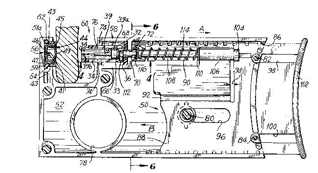
Referring to FIGS. l, 3 and 4 stud retaining sub-assembly
30 includes a rear support wall 32 and a casing 34 extending from :
support wall 32. Support wall 32 extends beyond casing 34 to
define flanges 36. Two bores 38 axially extend for the length of
casing 34 and through ~upport wall 32. Bore 38 receives a stud 39
having a head 39a and a piercing pin 39b on axis. The diameter of
each bore 38 is dimensioned with respect to the size of each stud
39 to snugly retain studs therein by an interference fit. Studs
39 are further retained within stud retaining sub-assembly 30 by
ribs 31 formed within bore 38. In an exemplary embodiment windows
37 are ~ormed parallel with each bore 38 and are axially aligned
with the piercing pin 39b to facilitate aiming the piercing earring
at the ear lobe. As seen in FIG. 4, a U-shaped groove 33 is formed
in the bottom surface of casing 34 and is formed with a first leg
33a and a second leg 33b each of which communicates with a base
33c. A chamfered corner 35 is formed where each leg 33a, 33b
communicates with base 33c forming the continuous U-shaped groove
33.
Reference i5 now made to FIGS. 1, 2, 7 and 9 wherein a
clutch retaining ~ub-as~embly 40, including a clutch housing 42 and
:
;. .
' ' ' '' . ' ' ' .~" ' ' ' ~ " '" .'' '
: !
:'' ,: ' ;
. ' . ' . ~ ''
. .
2~89032
clutches 47, is depicted. Each clutch 47 is formed of a single
piece of resilient metal having a C-shaped configuration forming
two s~mmetrical loops 43, having ends 41. An opening 49 is
provided in the metal for receiving piercing pin 39b of an earring
and is coaxial with the space between ends 63.
Housing 42 includes a solid molded casing. Casing 42
includes two clutch chambers 44 (shown in FIG. 1) formed by
parallel blind holes 45. Blind holes 45 are of sufficient depth
to permit the clutch 47 to be recessed from the outer surface of
the casing defining housing 42 so that clutch 47 is prevented from
accidsntally coming into contact with a person's finger. A nib 46
projects from blind hole 45 and is extended to rest between the end
~1 and loops ~3 of each clutch 47 to place in position and secure
clutch 47 in clutch chamber 44. When piercing pin 39b enters
opening 49 and continues until it is between ~nds 41 of loop 43,
the ends 41 are spread apart and no longer held by nibs 46.
Accordingly, each clutch chamber 44 is configured to releaseably
secure clutch 47 th~rein until clutch 47 is secured on a piercing
pin 39b of an earring after the ear ~obe has been pierced. Clutch
housing 42 is formed with top flange 51a and a bottom flange 51b.
Reference is now made to FIGS. 1-6 wherein push rod
assembly 50 and housing 48 are depicted. Housing 48 is a two piece
frame formed of molded halves 52, 54 wh:ich are substantially mirror
images of each other with the exception of an opening 53 formed in
mslded halve 52. Halve 52 is shown and described in detail as
representing both ~alve 52 and halve 53.
Housing 48 defines an anvil 56 and a stud retaining sub-
assembly receiving assembly 58 which are formed in opposed
relationship across a gap forming a ~addle region 60. Anvil 56 is
formed with a first slot 62 dimensioned to receive and retain
flange 51a of clutch retaining sub-assembly 40 and a second slot
64 to receive and retain flange 51b of clutch retaining sub-
assembly 40 maintaining clutch retaining sub-assembly 40 in
position during operation.
Stud retaining sub-assembly receiving portion 58 includes
a floor 66 and a top 68 separated by a rear wall 70 having an
opening 72 formed therein. A front wall 74 extends hetween floor
66 and top 68 to form a box for containing stud retaining sub-
. ~ . . I
: . - ~i . . . .
2~890~2
-- .
assembly 30 therein. Front wall 74 has an opening 76 formed
therein having the same shape as the outline of stud retaining sub-
assembly casing 34. Stud retaining sub-assembly 58 has a height
substantially equal to the height of support wall 32 and has a
length less than the length of stud retaining sub-assembly 30 so
that a portion of casing 34 always extends through opening 76.
Stud retaining sub-assembly 30 is slidably retained within stud
retaining sub-assembly 58 and slides between a first position in
which support wall 32 is flush against rear wall 70 and a second
position in which support wall 32 is flush against front wall 74.
Opening 76 is dimensioned so that front wall 74 contacts flanges
36 preventing stud retaining sub assembly 32 from passing entirely
through opening 76.
~ ousing 48, is formed with a finger opening 78 extending
therethrough adapted to receive a finger of the user. A plurality
of pins 80, 82 and 84 are mounted within housing 48 and maintain
pueh rod assembly 50 in position as well as guide push rod assembly
50 during movement of push rod assembly 50 as will be discussed in
detail below. Housing 48 is formed with a rear opening 86
extending substantially the entire height of housing 48. A portion
of push rod assembly 50 extends through opening 86 allowing
operation of push rod assembly 50. For simplicity of construction,
pins 80, 82, and 84 may be screws or the like for affixing housing
portion 52 to housing portion 54.
Push rod assembly 50 includes a base 88 having a
substantially L-shape. A push rod 90 is mounted on base 88 through
a pivotable hinge 92. A gap 94 extending between base 88 and push
rod 90 allowing movement of push rod 90 relative to base 88 about
pivotable hinge 92. By way of example, hinge 92 may be a living
hinge. Base 88 is provided with a plurality of substantially
parallel grooves 96, 98 and 100 formed therein which are
dimensioned to rcceive pins 80, 82 and 84 respectively so that base
88 is slidably disposed within housing 48. Pins 80, 82 and 84 also
aid in guiding base 88 as it moves within housing 48 while the end
of each respective groove 96, 98 and 100 prevents base 88 from
moving too far in either direction.
Base 88 is formed with a convexly shaped shoulder 102.
Shoulder 102 is convex to fit snugly between the index finger and
'
: . . , , ~
,
,'' : , , ' : ' . : , '
. . .
.
. .
~9~
7 !,
thumb of a variety of users having different sized hands. Ears 104
are formed on base 88 behind push rod 90 and are substantially
coaxial with bores 38. Push rod 90 is formed with a rear portion
106 and an engaging poxtion 108. Engaging portion 10~ has a
diameter smaller than rear portion 106 and a shoulder 110 is formed
therebetween.
~ ear portion 106 extends across gap 9~ and slidably
conkact~ ears 104. Engaging portion 108 extends through opening
72 of rear wall 70 o~ stud retaining sub-assembly receiving portion
48 and into bore 58 of stud retaining sub-assembly 30. Engaging
portion 108 slides within opening 72 as plunger 90 pivots about
living hinge 92 to be selectively coaxial with each bore 38. A
hook 112 is formed on engaging portion 108 and is disposed within
a U-shaped groove 33. A keeper 116 encircles a portion of engaging
portion 108 adjacent rear wall 70 and extends through opening 53
forming a button 118 outside of housing 48. Button 118 is formed
with a notch ll9 therein. Engaging portion 108 is slidably disposed
within keeper 116 so that keeper 116 does not interfere with the
forward motion of push rod 90. A spring 114 is disposed between
shoulder 110 and keeper 116 for biasing push rod 90 and in turn
base 88 therewith in the direction of arrow A (FIG. 3).
By utilizing a convex shaped shoulder 102 in cooperation
with finger opening 78 adjacent the anvil, as the user squeezes an
ear piercing assembly to push push rod assembly 50, ear piercing
assembly 20 is anchored within the pallm of the hand of the user
between the ~inger extending within finger opening 78 and the web
between the index finger and the thumb. Accordingly, the
instrument will be as steady as the hand of the user and th~ user
may utilize the extended index finger of the pierciny hand as one
further aiming device much as one would aim a gun. Further, by
utilizing a finger which is opposed to the thumb as anchorage in
finger opening 78, adequate leverage is now provided ~or the force
required to actuate push rod assembly 50.
In operation, an ear pier~ing assembly 20 is assembled
by moldiny stud retaining sub-assembly 30, clutch retaining sub-
assembly 40, push rod assembly 50 and housing 48 as individual
components. The components are then assembled into the single unit
/
.' ;,.. .
,' ,
8 ..
described above. The assembled ear piercing assembly 20 is then
sterilized, packaged and shipped to the end user.
In the shipped state, button 118 formed by keeper 116
extends out of housing 48 through opening 53. Rear portion 108 is
in contact with an ear 104 closest to housing portion 52. Hook 112
engages support wall 32 so that when spring 114 biases push rod 90
in the direction of arrow A, hooX 112 acts on support wall 32
maintaining support wall 32 flush against rear wall 72 of retaining
sub-assembly receiving portion 58. As a result stud retaining sub-
assembly 30 is substantially retracted within stud retaining sub-
assembly receiving portion 58. At the same time, base 88 extends
out from opening 86 of housing 48.
The user unwraps ear piercing assembly 20 and positions
housing 48 relative to an ear lobe 122 so that ear lobe 122 is
disposed within saddle region 60 (FIG. 3). Convex shoulder 102 is
placed between the forefinger and thumb o~ the user and the index
finger or the middle finger of the user is positioned through hole
78 to steady ear piercing assembly 20 during use. By squeezing
convex shoulder 102 towards housing 48, ears 104 drives rear
engaging portion 108 and in turn push rod 90 in the direction of
arrow B (FIGS. 2, 3). Push rod assembly 50 is moved in the
direction of arrow B so that push rod engaging portion 108 pushes
against stud 39. Because stud 39 is maintained in place within
stud retaining sub-assembly 30 by rib 31, engaging portion 108
pushing on stud 3~ moves-stud 39 which carries with it the entire
stud retaining sub-assembly 30 in the direction of arrow C (FIG.
7) so that flange 36 moves toward front wall 74. Ear lobe ~22 is
pinched and positioned between clutch retaining sub-assembly 40 and
stud retaining sub-assembly 30.
The instrument operator may use stud pins 39b as viewed
through opening 37a to ensure proper alignment between stud 39 and
the piercing target. Because stud retaining sub-assembly 30 is
blocked against ear lobe 122, continued pushing on push rod
assembly 50 causes engagement portion 108 of push rod 90 to push
stud 39 through bore 38 deflecting rib 31. Hook 112 travels along
leg 33a o~ U-shaped groove 33 so that there is no interference when
engaging portion 108 travels through bore 38. Engaging portion 108
. ~ .
... .
, . ' . ' ',
2 ~ 2
g .,
drives stud 39 through ear lobe 122 ~FIG. 9) so that clutch ends
41 engage stud pin 39b lifting clutch 47 from nib 46.
: Push rod assembly 50 is released so that bias spring 114
moves push rod assembly 50 in the direction o~ arrow A (FIG. 3).
This causes engaging portion 108 to move in the direction of arrow
A through bore 3B. Hook 112 of engaging portion 108 comes in
contact with support wall 32 so that as engaging portion 108
travels in the direction of arrow A hook 112 carries support wall
32 and retaining sub-assembly casing 34 with it returning stud
retaining sub-assembly 32 to the starting position, flush against
rear wall 70. This separates stud retaininy sub-assembly 30 from
the ear allowing ear lobe 122 to be removed from saddle area 60.
At this step during operation, conventional ear piercing
instruments require either movement of the retaining sub-assemblies
into a firing position or replacement of the retaining sub-assembly
which is now empty with a second retaining sub-assembly to pierce
either the same ear lobe again or opposite ear.
This type of physical bondage is avoided in the instant
~ invention. Specifically, button 118 of keeper 116 is pushed in the
- direction of arrow D (FIG. 6) causing push rod 90 to rotate about
pivotal hinge 92 in the direction of arrow E (FIG. 6). This causes
rear portion 106 to slide across ears 104 to be in contact with ear
104 adjacent body portion 54. At the same time, engaging portion
108 of push rod 90 slides through opening 72 as hook 112 slides
through base 33c of U~shaped groove 33 to be positioned behind the
- remaining stud 39 coaxially with the associated bore 38. Remaining
; stud 39 is in a cooperative position with remaining clutch 45.
Notch 119 catches on opening 53 preventing return of keeper ~16 to
i~s original position and in turn preventing reuse of ear piercing
assembly 20.
The process described above is repeated for piercing the
ear a second time. Accordingly, pressure is applied to shoulder
102 so that base 88 moves within housing 48 while ear 104 applies
a force behind push rod 90 to push stud retaining sub-assembly 30
into contact with ear lobe 122. Push rod 90 is then further pushed
into bore 88 moving hook 112 within leg 33b of U-shaped groove 33
displacing ribs 31 and driving stud pin 39b through ear lobe 122.
After piercing, shoulder 102 is released so that spring 114 biases
lo 2 ~ 8 ~ ~ 3 ~ ?
push rod assembly 50 in the direction of arrow A causing hook 112
to retract now ~mpty stud retaining sub-assembly 30 back into ~tud
retaining sub-assembly receiving portion 58. Assembly 20 is
disposable and therefore the assembly is now thrown away preventing
cros~-contamination with a later user.
By constructing an ear piercing assembly having a push
rod ass~mbly with a pivotable hinge ~o that the pu~h rod is
displaceable from ~ first position behind a first stud coaxial with
a retaininy sub-assembly bore to a second position behind a second
stud coaxial to a retaining sub-assembly bor~, without touching the
retaining sub-assembly, an ear piercing assembly which effectively
eliminates handling of the retaining sub-assemblies after
sterilization is provided. By utilizing a pivotable hinge and a
push rod assembly in a housing which may be formed of a few
integral molded piece~, the construction of the assembly is
simplified reducing costs making the instrument disposable.
Further, by designing an ear piercing assembly having a convex
shoulder and a finger hole adjacent the saddle region an anchoring
system for steadying the assembly within the palm of the user's
hand is provided.
It will thus be seen that the objects set forth above,
among those made apparent from the previous description, are
e~ficiently obtained and, since certain changes may be made in the
above construction without departing from the spirit and scope of
the invention, it is intended that a:Ll matter contained in the
above description or shown in the accompanying drawings shall be
interpreted as illustrative and not in a limiting sense.
It is also to be understood that the following claims are
intended to cover all of the generic and specific features of the
invention herein described and all statements of the scope of the
invention which, as a matter of language might be said to fall
therebetween.
:; .
. ............. . . . . . . .
' ' . : . : , .
.
, . . . . .
. ~ ' . .
: ! ' ' '