Sélection de la langue

Search

Sommaire du brevet 2090017 

Énoncé de désistement de responsabilité concernant l'information provenant de tiers

Une partie des informations de ce site Web a été fournie par des sources externes. Le gouvernement du Canada n'assume aucune responsabilité concernant la précision, l'actualité ou la fiabilité des informations fournies par les sources externes. Les utilisateurs qui désirent employer cette information devraient consulter directement la source des informations. Le contenu fourni par les sources externes n'est pas assujetti aux exigences sur les langues officielles, la protection des renseignements personnels et l'accessibilité.

Disponibilité de l'Abrégé et des Revendications

L'apparition de différences dans le texte et l'image des Revendications et de l'Abrégé dépend du moment auquel le document est publié. Les textes des Revendications et de l'Abrégé sont affichés :

  • lorsque la demande peut être examinée par le public;
  • lorsque le brevet est émis (délivrance).
(12) Demande de brevet: (11) CA 2090017
(54) Titre français: GUIDE POUR CYLINDRE D'ENROULEMENT LOURD
(54) Titre anglais: GUIDE FOR HEAVY WINDING ROLLER
Statut: Réputée abandonnée et au-delà du délai pour le rétablissement - en attente de la réponse à l’avis de communication rejetée
Données bibliographiques
(51) Classification internationale des brevets (CIB):
  • B65H 18/04 (2006.01)
  • B65H 16/06 (2006.01)
(72) Inventeurs :
  • HEHNER, REINHARD (Allemagne)
  • WELP, EWALD GEORG (Allemagne)
  • MULLER, GEORG (Allemagne)
(73) Titulaires :
  • JAGENBERG AKTIENGESELLSCHAFT
(71) Demandeurs :
  • JAGENBERG AKTIENGESELLSCHAFT (Allemagne)
(74) Agent: SMART & BIGGAR LP
(74) Co-agent:
(45) Délivré:
(86) Date de dépôt PCT: 1992-06-29
(87) Mise à la disponibilité du public: 1993-01-14
Licence disponible: S.O.
Cédé au domaine public: S.O.
(25) Langue des documents déposés: Anglais

Traité de coopération en matière de brevets (PCT): Oui
(86) Numéro de la demande PCT: PCT/EP1992/001460
(87) Numéro de publication internationale PCT: EP1992001460
(85) Entrée nationale: 1993-02-19

(30) Données de priorité de la demande:
Numéro de la demande Pays / territoire Date
P 41 23 304.2 (Allemagne) 1991-07-13

Abrégés

Abrégé anglais


- 7 -
ABSTRACT
Guide Head for Heavy Winding Drums
Guide heads having an essentially hollow cylindrical guide part which
can be driven into a tube (2) of the winding drum mounted on a hub (4,
5) so as to be angularly movable to a limited degree to adapt to the
deflection line of the winding tube, are known on winding machines for
winding or unwinding webs of material.
According to the invention, the guide part (6) is pivoted on a
twist-resistant hub (4, 5) with circular cross-section, whereby an
angularly movable radial bearing (8), and in front of it a peripheral,
radially elastically deformable support element (11) is placed between
the hub (4, 5) and the guide part (6) in the area of the hub end (hub
part 5). (Fig. 1).

Revendications

Note : Les revendications sont présentées dans la langue officielle dans laquelle elles ont été soumises.


- 6 -
PATENT CLAIMS
1. Guide head for heavy winding drums, having an essentially hollow
cylindrical guide part (6) which can be driven into a tube (2) of
the winding drum and is mounted so as to be angularly movable to a
limited degree on a hub (4, 5), c h a r a c t e r i z e d
t h e r e i n that the guide part (6) is pivoted on a
twist-resistant hub (4, 5) with circular cross-section, whereby an
angularly movable radial roller bearing (8) and, in front of that, a
peripheral, radially elastically deformable support element (11) is
arranged between the hub (4, 5) and the guide part (6) in the area
of the hub end (hub part 5).
2. Guide head according to claim 1, c h a r a c t e r i z e d b y a
self-aligning roller bearing or a self-aligning ball bearing as
angularly movable radial ball bearing (8).
3. Guide head according to claim 1 or 2, c h a r a c t e r i z e d
t h e r e i n that an elastic O-ring is placed as support element
(11) between the guide part (6) and a radial bearing (10) mounted on
the hub (hub part 4).
4. Guide head according to one of the claims 1 to 3,
c h a r a c t e r i z e d t h e r e i n that the guide part (2)
extends beyond the end of the hub (53 and is tightly sealed on the
inside with a disk (12).

Description

Note : Les descriptions sont présentées dans la langue officielle dans laquelle elles ont été soumises.

2~9~
RM.022~.W0
June 26, 1992
Jagenberg Aktiengesellschaft, DUsseldorf
D E S C R I P T I 0 N
Guide Head for Heavy Winding Drums
Technical Field
The invention concerns a guide head for heavy winding drums according to
the preamble of claim 1.
Guide heads are used on winding machines for winding up or unwinding
winding drums of paper or cardboard webs to hold the drums during the
winding up or unwinding. Two freely rotatable or drivable guide heads
each, supported in the winding machine (e.g. in rolling-up brackets),
travel into the hollow cylinder of the winding drum on each side.
If the winding drums are not supported during winding up and unwinding,
e.g. by a backing roll or bearing roll, the hollow cylinder in
especially heavy winding drums, which is usually made of cardboard, can
sag between the two guide heads due to the weight, which then leads to
defects in the rolls. The drum then turns somewhat eccentrically in the
area of the hollow cylinder, as a result of which restoring forces occur
during rotation which lead to shifts in the position of the roll. These
~; shifts in position can cause breaks and crimps in the core area of the winding drum.
; . ' . ' ' ' - : .
,

2 ~
Prior Art
A grip of this type, which is located on a drivable shaft end and
consis-ts of a guide part and a torque-transmitting part, is known from
DE 25 26 497-Bl. The guide part contains a hub connected with the shaft
end so as to be twist-resistant, having an essentially cylindrical,
slightly globular surface which is surrounded by a support tube. The
support tube has axial slots distributed over the periphery on -the end
placed in direction of the shaft end, so that it can carry out an
inclined movement to enable its peripheral area to follow the deflection
line of the winding tube. The second part connected with the guide part
so as to be twist-resistant has a segmented tube repeatedly slotted
axially with pressure elements which push the segments radially outward
when the segmented tube is turned, so that torques can be transmitted.
The second part has a radial clearance vis-a-vis the first part and can
be inclined so that it can adapt to the alignment of the tube. By
adapting the two parts to the deflection line of the winding tubes, the
stress on the winding tubes is reduced at their ends.
This grip with radially expanding bracing segments, which is very
expensive to construct, is designed so as to transmit torques. The
guide part sits on the driven sha-ft so as to be twist-resistant, which
must therefore be pivoted to a great extent in the winding machine.
::~
` Des~ription o~ -the Invention
:
The object of the invention is to create a guide head which is easy to
construct and which can adapt to the deflection line of a tube.
~ .
,~
~ ` .
,~
:, ~ .

2 ~ 7
This object is solved with the features of claim 1.
According to the invention, the guide part is pivoted on a hub which is
twist-resistant and thus easy to mount in the winding machine. If there
are no outer radial forces, the support element centres the guide part
coaxially to the pivot axis so that the guide heads can be driven into
new winding tubes without difficulty.
The arrangement of the pivot bearing in the area of the hub end, that
is, outside of -the machine part to which the guide head is fastened, has
the further advantage that the twist-resistant hub can be mounted in a
structurally simple manner so as to be axially displaceable, e.g. by a
centrally acting worm drive. Since the two guide heads holding a
winding drum must be driven apart in axial direction for removing or
replacing a winding drum or a winding tube, this can take place wi-thout
that part of the machine moving to which the guide heads are attached.
The guide heads can simply be lowered in the machine part.
The subclaims contain preferred embodiments of the invention as they are
especially advantageous.
Short Descri pti on o~ the Drawi ng
The drawing is used to explain the invention with reference to a
simplified illustration of an embodiment.
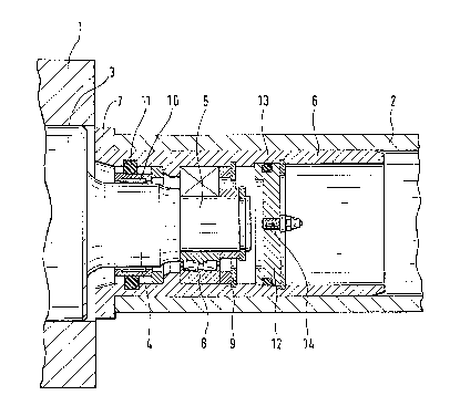
Fig. 1 shows a longitudinal section through a guide head of the
invention.
,,; , , ' , .
:

2 0 ~
Method for Carrying Out the Invention
The guide head shown in Fig. l is used to hold a winding drum when it is
being wound up in a wind1ng machine. The known winding machines for
winding up heavy winding drums of paper or cardboard webs have
individual winding stations which each consist of two rolling-up
brackets l, one of which is shown in part in Fig. l. A guide head,
which can be inserted into the tube 2 of a winding drum, described in
greater detail below, is fastened to each rolling-up bracket l.
The guide head consists of a hub 3, 4, S having a circular cross-section
which is mounted so as to be twist-resistant and axially displaceable
with its part 3 in the rolling-up bracket l by means of a worm drive for
lowering the guide head when changing a winding drum. In -the withdrawn
operating position of Fig. l, the end of -the hub 3 consisting of two
parts 4, 5 each having a decreasing diameter, is outside of the
rolling-up bracket l. A hollow cylindrical outer guide part 6 is
pivoted on the parts 4, 5, the outer diameter of which is adap-ted to the
inside diameter of the tube 2. The guide part 6 has an annular collar 7
for the tubes 2 on its end facing the rolling-up bracket l, on the other
end, it extends beyond the hub by the length of the parts 4, 5 of said
hub 3.
::
The guide part 6 is fastened to the hub 3 by means of an angularly
movable radial ball bearing 8, located in the area of the outer part 5,
so as to be pivotable and tiltable to a limited degree. Preferably, the
angularly movable radial ball bearing 8 is a self-aligning roller
bearing (as in the present example) or a self-aligning ball bearing, the
outside bearing raceway of which is set on the inside surface of the
gui~e part 6 and the lnner bearing raceway on the outside surface of the
,
: , :
, ~ ' ' ' ,
'
: ~ ,:
.
,

2 ~ 7
hub part 5. The self-aligning roller bearing 8 is secured against an
axial displacement by a retaining ring 9.
The beginning of the guide part 6 is pivoted on the hub part 4 and
braced by a peripheral, raclially elastically deformable element. For
this purpose, there is a needle roller bearing 10 on the hub part 4,
over whose ou-ter roller path an elastic 0-ring 11 is pulled. The 0 ring
11 presses the guide part 2 into a position coaxial to the axis of the
hub 3, that is, if there are no outside forces, e.g. the weight of the
rollers. The 0-ring 11 simultaneously seals the guide head on the
inside on the side facing the rolling-up bracket 1.
At a slight distance from the end of the hub part 5, the guide part 2 is
sealed on the inside with a clisk 12 which is sealed with a sealing ring
13 and has a central lubricating opening 14. Lubricant can be conveyed
via opening 14 into the space thus sealed by the two bearings 8, 10.
When winding or unwinding heavy winding drums ~width ~ 2300 mm, diameter
1150 mm), the tube 2 of the winding drum held laterally by two guide
heads sags due to the weight. The guide part 6 of the guide head is in
a position to follow the deflection line of the tube 2, it adapts to the
deflection line of the tube 2 by tilting at right angles to the pivot
axis. The tilting movement is limited by the 0-ring 11, the tipping
angle to the pivot axis is 10 max., preferably between 0.5 and 5. Due
to the adaptation of the guide part 6 to the deflection curve of the
tube 2, restoring forces which lead to displacements in the position of
the drum during winding or unwinding are essentially avoided. These
displacements in position in the core area of the winding drum can lead
to breaks and crimps.

Dessin représentatif
Une figure unique qui représente un dessin illustrant l'invention.
États administratifs

2024-08-01 : Dans le cadre de la transition vers les Brevets de nouvelle génération (BNG), la base de données sur les brevets canadiens (BDBC) contient désormais un Historique d'événement plus détaillé, qui reproduit le Journal des événements de notre nouvelle solution interne.

Veuillez noter que les événements débutant par « Inactive : » se réfèrent à des événements qui ne sont plus utilisés dans notre nouvelle solution interne.

Pour une meilleure compréhension de l'état de la demande ou brevet qui figure sur cette page, la rubrique Mise en garde , et les descriptions de Brevet , Historique d'événement , Taxes périodiques et Historique des paiements devraient être consultées.

Historique d'événement

Description Date
Inactive : CIB de MCD 2006-03-11
Le délai pour l'annulation est expiré 1998-06-29
Demande non rétablie avant l'échéance 1998-06-29
Réputée abandonnée - omission de répondre à un avis sur les taxes pour le maintien en état 1997-06-30
Demande publiée (accessible au public) 1993-01-14

Historique d'abandonnement

Date d'abandonnement Raison Date de rétablissement
1997-06-30
Titulaires au dossier

Les titulaires actuels et antérieures au dossier sont affichés en ordre alphabétique.

Titulaires actuels au dossier
JAGENBERG AKTIENGESELLSCHAFT
Titulaires antérieures au dossier
EWALD GEORG WELP
GEORG MULLER
REINHARD HEHNER
Les propriétaires antérieurs qui ne figurent pas dans la liste des « Propriétaires au dossier » apparaîtront dans d'autres documents au dossier.
Documents

Pour visionner les fichiers sélectionnés, entrer le code reCAPTCHA :


Pour visualiser une image, cliquer sur un lien dans la colonne description du document. Pour télécharger l'image (les images), cliquer l'une ou plusieurs cases à cocher dans la première colonne et ensuite cliquer sur le bouton "Télécharger sélection en format PDF (archive Zip)" ou le bouton "Télécharger sélection (en un fichier PDF fusionné)".

Liste des documents de brevet publiés et non publiés sur la BDBC .

Si vous avez des difficultés à accéder au contenu, veuillez communiquer avec le Centre de services à la clientèle au 1-866-997-1936, ou envoyer un courriel au Centre de service à la clientèle de l'OPIC.


Description du
Document 
Date
(aaaa-mm-jj) 
Nombre de pages   Taille de l'image (Ko) 
Abrégé 1993-01-13 1 15
Dessins 1993-01-13 1 26
Revendications 1993-01-13 1 28
Description 1993-01-13 5 150
Dessin représentatif 1999-05-09 1 20
Courtoisie - Lettre d'abandon (taxe de maintien en état) 1997-09-21 1 188
Taxes 1996-05-21 1 73
Taxes 1995-05-30 1 66
Taxes 1994-05-11 1 61
Rapport d'examen préliminaire international 1993-02-18 14 536