Note : Les descriptions sont présentées dans la langue officielle dans laquelle elles ont été soumises.
W~ 93/~0~12 PCT/~P92tO139g
2 ~
P~OTOG~AP~IC PR~C~SSI~ APP~T~S
This i~vention relates to photographic
processing apparatus and is more particularly
c~ncerned with such apparatus in which chemically
unstable solutions are utilised.
Conventional colour photographic silver
halide materials are processed by a process which
includes a coloux development step. In this step
silver halide is reduced to metallic silver in the
light-exposed areas and the oxidised colour developer
formed in ~his reaction then couples with a colour
coupler and forms image dye. The amount of dye
produced is proportional to the amount of silver
nalide reduced to metallic silver.
Redox amplification processes have been
described, for example in British Patent
Specifications GB-A-1 268 126, GB A-1 399 481,
GB-A-1 403 418 and GB-A-l 560 572n In such processes
colour matexials are developed to produce a silver
20 image ~which may contain only small amounts of silver~ ~
and then ~reatPd with a redox amplifying solution to r
form a dye image. The redox amplifying solution
contains a reducing agen~, for example a colour
developing agent, and an oxidising agent which is more
25 powerful ~han silver halide and which wiIl oxidise the
colour developing agent in the presence of the silver
image which acts as a catalyst. Oxidised colour
developer reacts with a colour coupler (usually
contained in the photographic material) to form image
30 dye. The amount of dye formed depends on the time of
; treatment or the availability of colour coupler xather
than the amount o~ silver in the image as is the case
in conventional colour development processes.
Examples of suitable sxidising agents include peroxy
compounds including hydrogen peroxide, cobalt ~
WO93/00612 PCT/EP~2/01398
--2--
complexes including cobalt hexammine complexes, and
periodates. Mixtures of such compounds can also be
used.
Since the amplifying solution contains both
an oxidising agent and a reducing agent it is
inhexently unstable. That is to say unlike a
conventional colour developer solution, amplifier
solutions will deteriorate in a relatively short time
even if left in a sealed container. The best
reproducibility for such a process has been obtained
by using a "one shot" system, where the oxidant is
added to the developer and the solution mixed and used
immediately ~or after a short built in delay) and then
discarded. This leads to the maximum solution usage
possible with maximum effluent and maximum chemical
costs. As a result the whole system is unattractive
especially for a minilab environment where minimum
effluent is required. It is believed that it is these
shortcomings tha. have inhibited commercial use of
this process.
Japanese Specification 64/44938 appears to
describe such a system in which a silver chloride
colour material is processed in a low volume of a
single-bath amplirier solution. The processes
described therein however fall short of what is
required in the fully commercial environment for
exactly the reasons given above.
WO-A-9l/12567 (eorresponding to British
Patent Application No. 9003282.2~ describes a method
and apparatus for photographic processing in which a
minimum amount of processing solution can be used in a
processing tank which is thin and has a low volume.
In order to overcome the inherent deterioration
problem due to the instability of the processing
solutions used, the method and apparatus described
.
.~
WO93/00612 PCr/EP92/0l398
. ~
~3~ 20903~6
result in the need for high recircula~ion and/or
replenishment rates. However, problems associated
with non-uniform processing of the photographic
material may be encountered due to local differences
in the concentration of the processing solution.
US-A-4 512 645 discloses a tank arrangement
for the processing of photographic material in which
improved material transportation and chemis~.ry
circulation are provided. This is achieved by having
a tank with an integrally formed round botto~ with a
hollow cont~ured tank divider. The tank divider has
an inlet port through which processing solution is
added. A plurality of apertures are formed along the
length of the divider through which processing
15 solution is applied to the emu'sion surface of the ;!
material being processed. Processing solution is
discharged from the tank via an overflow port. In
this arrangement, contact between the emulsion surface
- of the material and the walls of the tank is reduced
due to the concave shape of the tank divider. This
concave shape also allows processing solution to be
circulated within the tank prior to its discharge via
the overflow port.
However, the tank arrangement described in
25 US-A-4 512 645 requires a relatively large amount of
processing solu~ion to be present in the tank, and
there is no recirculation of the solution. Such an
arrangement, however, is unsuitable for use with
unstable processing solutions as discussed abo~eO
One problem associated with continuous
processing in a tank having a low volume (typically
100ml for a tank having a thickness of 1.5mm, a width
of 125mm and a path leng~h of 55~mm), is ~o obtain
sufficient agitation of the processing solution. This
problem arises because processing solution adheres to
.. . . .. ..
.
: ~ . . ':
WO~3/00612 PCT/EP~2/0139g
the emulsion surface of the material being processed
and it is not removed (wiped off), and access of fresh
processing solution to the emulsion surface is
restricted in the narrow confines of the tank.
It is therefore an ob~ect of the present
invention to improve access of processing solution to
the emulsion surface of the material being processed,
and as a result, provide more uniform processing of
the photographic material.
According to one aspect of the pres~nt
invention, there is provided photographic processing
apparatus for processing photographic material, the
apparatus comprising:-
a processing tank;
at least one feed aperture through which
processing solution is added to the processing tanki
and
at least one exit aperture through which
sslution is extracted from the tank for recirculation
and replenishment;
characterized in that spacing means are
provided along a wall of the tank over each of the
feed apertures to keep the material away from the tank
wall.
By this arrangement, recirculation of the
processing solution in the tank aids agitation and
prevents the formation of drag lines and uneven
processing by mixing replenisher and the tank solution
efficiently and by forcing the solution against the
emulsion surface.
For a better understanding of the present
invention, reference will now be made~ by way of
example only, to the accompanying drawings in which:-
Figure 1 is a schematic sectioned view
through a low volume processing tank; and
.
W~/00612 PCTtEP92/al398
~5~ 2~9031~
Figure 2 is an enlarged, fragmentary
sectioned view throuyh the tank shown in Figure l
which shows an element according to the present
inven~ion in detail.
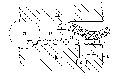
Figure l shows a low volume processing tank
lO. The tank lO is defined by an outer wall 12 and an
inner wall 140 The spacing between outer wall 12 and
inner wall 14 is l.5mm.
Figure 2 illustrates a portion of the tank
lO and in particular, an element l6 according to thepresent invention. A number of elements l6 can be
fitted along the entire path length of the tank lO.
Element l6 comprises a piece of plastic mesh
which is approximately 0.350mm thick and having a
filament pitch of 1.5mm. The element 16 is positioned
to cover a feed slot 18 formed in inner wall l9, and
is glued in place using a suitable adhesive. ~eed
slot l8 extends across the entire width of the ~ank
lO. Processing solution is supplied from a feed
cavity 20 to the feed slot 18 and then enters the tank
10 .
Alternatively, the feed slot 18 may comprise
a series of feed holes which extends across the width
of the tank lO. In this case, the element 16 needs to
be continuous at least in the region of the feed holes
so that the processing solution entering the tank lO
through the hcles is propoerly circulated. Away from
the holes, the element l6 can be a mesh as described
above.
A piece of photographic paper 24 is shown
with its emulsion surface 26 facing inner wall 14.
Element 16 prevents the surface 26 contacting ~all 14.
Additi~nally, the force of the processing solution
coming out of the feed slot l8.
, .
, -
. .
WO93/00612 PCT/EP92tO1398
3~6 -6-
At least one side exit port 22 is provided
to remove processing solution from the tank 10. Exit
ports 22 are connected to t.he feed slots 18 via feed
cavity 20 and allow processing solution to be
S recirculated using a pump arrangement (not shown).
This has the ef~ect of flushing the emulsion surface
26 of the paper 24 with processing solution which has
been both recirculated and replenished. The ~lushing
of the emulsion surface 26 aids agitation and leads to
uni~orm processing.
Agitation members ~not shown) may also be
present in the tank 10. These members improve
agitation between the feed slots 18 and side exit
ports 22 through which processing solution is taken
out of the tank 10 and returned to it via the feed
slots 18. In practice, a number of feed slots 18 are
positioned throughout the path length but only one or
two exit ports 22 are required.
Processing solution in tank 10 is
recirculated at a high rate typically 800mlmin 1.
- This corresponds to circulating one tank volume every
8 to 15s. Agitation is improved if the direction of
recirculating flow is opposite to that of the
direction of paper transport.
During the recirculation, the processing
solution is replenished, and the combined solution is
reheated before being pumped back through feed slot
18. Low volume pipes and pumps are used to keep the
total volume to an acceptable minimum level.
In the case of RX chemistry, the
recirculation system allows for an instant start up
because the tank and recirculation system can be kept
filled with the developer/amplifier solution, and when
required, starter solution and hydrogen peroxide can
be pumped into the recirculation loop.
- . .: - ~ -:. ..,.~. - :. . : ; -
- - ::,: .: .::.. : . .:. . .- , ,
,: . ,
W093~0~12 PCT/EP92/01398
2Q9~3~
The number of feed slots 18 may be varied,
with between two and five slots being provided for a
path length of approximately 550mm. The recirculation
rate may also be varied from approximately 300mlmin
to 8QOmlmin~1 for an approximate total system volume
(the total volume of solution required for the tank
and its associated low volume pipes and pumps) of
between 150ml and 270m} respectively. The normal rate
of addition of replenisher under these conditions is
about 4Omlmin 1.
Higher rates of recirculation could be used,
e.g. 2 to 41min . However, at these higher rates the
pressure in the system would be increased because it
is still necessary to minimise the total volume of the
system (i.e. tank plus pipes plus pumps).
The feed slot 18 shown in Figure 2 is 0.40mm
wide and 5 to lOmm deep to connect with the feed
cavity 20. The feed cavity 20 has a diameter of
approximately 2.5mm.
The width of the feed slot 18 may be
important a wider slot being able to deli~er more
solution to the emu~sion surface at a given pressure.
However, the uniformity of solution supply across the
length of the slot also needs to be considered.
The size of the feed cavity 20 may also be
important. A larger sized cavity may be more
advantageous in that it would give a more uniform
supply of solution to the emulsion surface.
The element 16 shown in Figure 2 was tested
in a U-shaped tank with the emulsion surface facing
the inside of the bend (that is, away from outer wall
12) as it travelled through the tank 10. However, the
emulsion surface may be required to face the cther way
in other tank arrangements. In some other tank
.. .. . .. . . . . . . ... ...
... . ... . .
.: . .. ~ . . . . .
W0~3/00~12 PCT/EP92/01398
-3~
arrangements, it may be necessary to move the feed
cavities and slots to the outer wall 1~.
Alternatively, element 16 can be removed
provided the surface of wall 14 is textured to prevent
the emulsion surface adhering to it.
. . .
t
' "' ` -'-: ~ -:- " . - :