Sélection de la langue

Search

Sommaire du brevet 2091284 

Énoncé de désistement de responsabilité concernant l'information provenant de tiers

Une partie des informations de ce site Web a été fournie par des sources externes. Le gouvernement du Canada n'assume aucune responsabilité concernant la précision, l'actualité ou la fiabilité des informations fournies par les sources externes. Les utilisateurs qui désirent employer cette information devraient consulter directement la source des informations. Le contenu fourni par les sources externes n'est pas assujetti aux exigences sur les langues officielles, la protection des renseignements personnels et l'accessibilité.

Disponibilité de l'Abrégé et des Revendications

L'apparition de différences dans le texte et l'image des Revendications et de l'Abrégé dépend du moment auquel le document est publié. Les textes des Revendications et de l'Abrégé sont affichés :

  • lorsque la demande peut être examinée par le public;
  • lorsque le brevet est émis (délivrance).
(12) Brevet: (11) CA 2091284
(54) Titre français: HOTTE AVEC TRINGLERIE DE COMMANDE DES CHICANES
(54) Titre anglais: FUME HOOD WITH BAFFLE CONTROL LINKAGE
Statut: Périmé et au-delà du délai pour l’annulation
Données bibliographiques
(51) Classification internationale des brevets (CIB):
  • B08B 15/02 (2006.01)
(72) Inventeurs :
  • BECK, MARSHALL K. (Etats-Unis d'Amérique)
(73) Titulaires :
  • HAMILTON INDUSTRIES, INC.
(71) Demandeurs :
  • HAMILTON INDUSTRIES, INC. (Etats-Unis d'Amérique)
(74) Agent: BORDEN LADNER GERVAIS LLP
(74) Co-agent:
(45) Délivré: 1999-11-09
(22) Date de dépôt: 1993-03-09
(41) Mise à la disponibilité du public: 1994-03-19
Requête d'examen: 1996-08-12
Licence disponible: S.O.
Cédé au domaine public: S.O.
(25) Langue des documents déposés: Anglais

Traité de coopération en matière de brevets (PCT): Non

(30) Données de priorité de la demande:
Numéro de la demande Pays / territoire Date
948,949 (Etats-Unis d'Amérique) 1992-09-18

Abrégés

Abrégé anglais


A fume hood with at least one adjustable baffle
includes a baffle control linkage for adjusting the position of
the baffle. This baffle control linkage includes a first
pivoting member, a second pivoting member, a handle for driving
the first pivoting member, and a linking device for connecting
the first and second pivoting members.

Revendications

Note : Les revendications sont présentées dans la langue officielle dans laquelle elles ont été soumises.


CLAIMS
1. In a fume hood with a housing defining a chamber with a front opening, at
least
one baffle pivotally mounted, at its bottom end, to the housing at the rear of
the chamber,
and a baffle control linkage including: a first pivoting member pivotally
mounted to the
housing proximate the front of the housing; a second pivoting member pivotally
mounted to
the housing proximate the baffle for moving the baffle, said second pivoting
member
including means for releasably engaging the baffle and a yoke portion which
receives a side
edge portion of the baffle; handle means secured to the first pivoting member
for driving
the first pivoting member; and linking means for connecting the first and
second pivoting
members, one end of said linking means being pivotally connected to the first
pivoting
member and an opposite end being pivotally connected to the second pivoting
member.
2. The fume hood of claim 1, wherein the housing includes outer and inner side
panels and the baffle control linkage lies mounted between the outer and inner
side panels.
3. The fume hood of claim 2, wherein the handle means extends outwardly of the
outer and inner panels and the housing and the second pivoting member extends
into the
chamber of the fume hood to engage the baffle.
4. The fume hood of claim 1, wherein the first and second pivoting members
pivot
about substantially parallel axes.
5. In a fume hood with a housing defining a chamber with a front opening and
including a front panel and inner and outer side panels, at least one baffle
being pivotally
mounted, at its bottom end, to the housing, a baffle control linkage being
disposed
substantially between the inner and outer side panels and including: a first
pivoting
member pivotally mounted to the housing proximate the front of the housing; a
second
pivoting member pivotally mounted to the housing proximate the baffle, said
second
pivoting member extending into the chamber of the fume hood and including a
yoke portion

for releasably engaging the baffle; handle means secured to the first pivoting
member for
driving the first pivoting member, said handle means extending outwardly of
the housing
through an opening in the front panel; linking means for connecting the first
and second
pivoting members, one end of said linking means being pivotally connected to
the first
pivoting member and an opposite end being pivotally connected to the second
pivoting
member; and the first and second pivoting members being pivotable about
substantially
parallel axes.
6. In a fume hood with a housing defining a chamber with a front opening, at
least
one baffle pivotally mounted to the housing and a baffle control linkage
including: a
pivoting member pivotally mounted to the housing proximate the baffle for
releasably
engaging an edge portion of the baffle and for moving the baffle; and a
driving member for
driving the pivoting member, said driving member including handle means for
holding the
driving member and connecting means for connecting the handle means with the
pivoting
member, said pivoting member including a yoke portion which receives an edge
portion of
the baffle.
7. In a fume hood with a housing defining a chamber with a front opening, at
least
one baffle pivotally mounted, at its bottom end, to the housing at the rear of
the chamber,
and a baffle control linkage including: a first pivoting member pivotally
mounted to the
housing proximate the front of the housing; a second pivoting member pivotally
mounted to
the housing proximate the baffle for moving the baffle, said second pivoting
member
including means for releasably engaging the baffle; handle means secured to
the first
pivoting member for driving the first pivoting member; and linking means for
connecting
the first and second pivoting members, one end of said linking means being
pivotally
connected to the first pivoting member and an opposite end being pivotally
connected to the
second pivoting member, the housing including outer and inner side panels and
the baffle
control linkage being mounted between the outer and inner side panels, the
handle means
extending outwardly of the outer and inner panels and the housing and the
second pivoting
member extending into the chamber of the fume hood to engage the baffle, the
second

pivoting member including a first segment disposed between the outer and inner
side
panels, the linkage means being pivotally secured to the first segment, and a
second
segment disposed substantially in the chamber, the second segment including a
pivot portion
which extends through an opening in an inner panel to engage the first segment
and a yoke
portion which receives a side edge portion of the baffle.

Description

Note : Les descriptions sont présentées dans la langue officielle dans laquelle elles ont été soumises.

FUME HOOD WITH BAFFLE CONTROL LINKAGE
BACKGROUND OF THE INVENTION
Field Of The Invention
The present invention relates to a fume hood with a
baffle control linkage. More particularly, this invention
relates to a fume hood with a control linkage which allows an
operator to adjust a baffle disposed at the rear of the fume
hood by manipulating a handle at the front of the fume hood.
In many applications, fume hoods must exhaust lighter
than air and heavier than air fumes. For exhausting lighter
than air fumes, a fume hood should include a baffle system which
allows the blower of the fume hood to pull air from an upper
portion of the hood chamber. For exhausting heavier than air
fumes, the baffle system should allow the blower to pull air
from a bottom portion of the hood chamber.
The fume hood described in U.S. Patent No. 4,434,711
includes a baffle system and an assembly for adjusting a damper
used with the baffle system. The damper assembly for this fume
hood includes a control handle which a user may move inwardly
- 1 -

2d~12~~
or outwardly of the fume hood and lock into a particular
position. Some operators, e.a. the disabled, find this control
handle and damper assembly difficult to operate. In addition,
when the handle extends a substantial distance outwardly of the
fume hood, it may snag clothing or act as an obstruction.
The fume hood of the present invention has a baffle
control linkage which allows easy and quick adjustment of the
baffle system. It meets the requirements of the Americans With
Disabilities Act. and it minimizes the outwardly extension of a
control handle. In addition, it allows easy removal of the
baffles from the fume hood for cleaning and repair. It is a
simple assembly which minimizes the cost of manufacture and
assembly and gives precise, uniform and reliable performance.
~rM~RV OF THE INVENTION
In accordance with one embodiment of this invention, a
fume hood includes a housing which defines a chamber and a front
access opening for the chamber. The housing also includes a
front panel and inner and outer~side panels. A baffle assembly
With at least one baffle pivotally mounted to the rear of the
chamber cooperates with a blower to evacuate the chamber of
fumes. A linkage control assembly allows an operator to adjust
this baffle.
Tha baffle control linkage includes a first pivoting
member pivotally mounted to the fume hood housing proximate the
front of the housing. It also includes a second pivoting member
- 2 -

2DD~.~84
pivotally mounted to the housing proximate the baffle; handle
means secured to the first pivoting member for driving the first
pivoting member; and a linking means for connecting the first
and second pivoting member. The second pivoting member includes
a portion which extends into the chamber and releasably engages
the baffle.
An operator may move the handle means, and thus the
first pivoting member, between predetermined limits. The
linkage means transfers the movements of the first pivoting
member to the second pivoting member. The second pivoting
member rotates and moves the baffle which lies pivotally
mounted, at its bottom edge, to the fume hood housing.
For a more complete understanding of the present
invention, one should now refer to the embodiment illustrated in
greater detail in the accompanying drawings and described below
as an example of the invention. In the drawings:
FIG. 1 is a perspective view of the fume hood of the
present invention, showing the baffle control linkage:
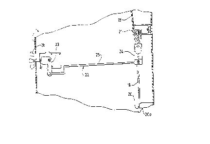
FIG. 2 is a side elevation view of the baffle control
linkaget
FIG. 3 is a partial perspective and exploded view of
the second pivoting member of the baffle control linkage.
While the following describes the invention in
connection with one embodiment, one should understand that the
- 3 -

invention is not limited to this embodimen ~ ~ ~~~~e~ore, one
should understand that the drawings are not to scale and that
graphic symbols, diagrammatic representations, and fragmentary
views may, in part, illustrate the embodiment. In certain
instances, the disclosure may not include details which are not
necessary for the understanding of the present invention.
nFTATLED DESCRTPTTON OF THE DRAWINGS
In the illustration given and with reference to FIG. 1,
the numeral 10 designates the fume hood of the present
invention. This fume hood generally includes a housing 11 and a
blower (not shown). The housing defines a chamber 12 with a
front opening 13 and comprises inner and outer panels, including
a front panel 14, inner side panels 15, and outer side panels
(not shown). A sash 16 slidably mounted to the portions of the
housing il adjacent the chamber opening 13 opens and closes the
opening 13. The housing 11 and the various components described
below are members made out of metal, hard plastic, or any other
material of sufficient strength, rigidity and corrosion
resistance.
& baffle system, including a lower baffle plate 17, a
middle batfle plate 18 and a top baffle plate 19 disposed in the
chamber 12, cooperates with the blower to exhaust fumes from tha
chamber 12. These baffle plates are made of cement board or a
polyester material. Alternatively, they may be made of
polyvinyl chloride, polypropylene, ar any other suitable
- 4 -

2~~128~
materials. The baffle plates 17-19 lie in the chamber 12
releasably secured to the back of the fume hood housing,
Certain clip and bracket structures made of polyester or other
suitable materials secure the baffles to the housing il. These
clips and brackets include brackets 20 (see FIG. 2) which
support the bottom portion of baffle plate 18 and which hold the
top of the bottom baffle plate 17. They also include brackets
21 which support the bottom portion of baffle plate 19.
A baffle control linkage 22 adjusts the position of the
middle baffle plate 18 to increase or decrease the gap between
the bottom end of the top baffle plats 19 and the top end of
middle baffle plate 18. By closing this gap, the operator may
direct the sucking action of the fume hood's blower to the
bottom of the chamber 12, to a gap between the bottom edge of
the plate 18 and the top edge of the plate 17 or between the
bottom edge of the baffle plate 17 and the floor of the chamber
12. Thus, the blower may remove heavier than air fumes at the
bottom of the chamber 12. By opening the gap, the operator may
direct the suction to the gap so that the blower removes the
lighter than air fumes at the top of the chamber 12.
The baffle control linkage 22 includes a first pivoting
member 23 pivotally mounted to the inner panel 15 proximate the
front of the fume hood, a second pivoting member 24 pivotally
mounted to the inner panel l5 proximate the back of the fume
hood, a linking arm 25 which connects the first and second
_ 5 _

~~~~zg~
pivoting members 23 and 24, and a handle 26 fixedly secured to
the first pivoting member 23. Suitable pivot connections secure
one end of linking arm 25 to the first pivoting member 23 and
the opposite end of the linking arm 25 to the second pivoting
member 24.
The second pivoting member 24 (See FIG. 3) includes a
first segment 27 which lies between an inner side panel 15 and
an outer side panel and a second segment 28 which lies in the
chamber 12. The segment 27 has one end pivotally connected to
the linking arm 25 and the other end fixedly secured with bolts
or similar means to the segment 28. The segment 28 is made of
corrosion resistant material (e.a., polyester) and includes a
pivoting portion 29 and a yoke portion 30. The pivoting portion
29 has a circular configuration and extends through a corre-
sponding opening 31 defined by the inner panel 15. This opening
31 has a diameter slightly greater than the diameter of the
pivoting portion 29 and allows the pivoting portion 29 to rotate
within it. The yoke portion 30 receives a side edge portion of
the middle baffle plate 18 which lies unsecured in the recess
formed by the yoke portion. This yoke portion 30 allows easy
removal og the baffle plate 18 for cleaning or repair:
When an operator moves the handle 26 in a clockwise or
counter-clockwise direction, the first pivoting member 23 pivots
in the same direction. The linking arm 25 transfers this move-
went to the second pivoting member 24 and drives the pivoting
member 24 in the same direction of rotation as that of the
- 6 -

2091284
pivoting member 23. When an operator moves the handle 26
upwardly, i.e., clockwise, the second pivoting member 24 tilts
the middle baffle 18 rearwardly or clockwise. Conversely, when
the operator moves the handle downwardly, the first and second
pivoting members move counter-clockwise: and the second pivoting
member tilts the middle baffle in a forward or counter-clockwise
direction. The baffle plate 18 pivots in recesses 20a of the
brackets 20. The top edge portion of the plate 18 does not
engage the bottoms of the brackets 21 (See FIG. 2).
While the applicant has shown one embodiment of the
present invention, one will understand, of course, that the
invention is not limited to this embodiment, as those skilled in
the art to which the invention pertains may make modifications
and other embodiments of the principles of the invention,
particularly upon considering the foregoing teachings. The
applicant, therefore, by the appended claims, intends to cover ,.
any modifications and other embodiments which incorporate those
features which constitute the essential features of this
invention.
What is claimed is:
,::

Dessin représentatif
Une figure unique qui représente un dessin illustrant l'invention.
États administratifs

2024-08-01 : Dans le cadre de la transition vers les Brevets de nouvelle génération (BNG), la base de données sur les brevets canadiens (BDBC) contient désormais un Historique d'événement plus détaillé, qui reproduit le Journal des événements de notre nouvelle solution interne.

Veuillez noter que les événements débutant par « Inactive : » se réfèrent à des événements qui ne sont plus utilisés dans notre nouvelle solution interne.

Pour une meilleure compréhension de l'état de la demande ou brevet qui figure sur cette page, la rubrique Mise en garde , et les descriptions de Brevet , Historique d'événement , Taxes périodiques et Historique des paiements devraient être consultées.

Historique d'événement

Description Date
Inactive : Renversement de l'état périmé 2013-10-09
Le délai pour l'annulation est expiré 2013-03-11
Lettre envoyée 2012-03-09
Accordé par délivrance 1999-11-09
Inactive : Page couverture publiée 1999-11-08
Inactive : Taxe finale reçue 1999-08-11
Préoctroi 1999-08-11
Lettre envoyée 1999-02-18
Un avis d'acceptation est envoyé 1999-02-18
Inactive : Renseign. sur l'état - Complets dès date d'ent. journ. 1999-02-16
Inactive : Dem. traitée sur TS dès date d'ent. journal 1999-02-16
Inactive : Approuvée aux fins d'acceptation (AFA) 1998-12-21
Exigences pour une requête d'examen - jugée conforme 1996-08-12
Toutes les exigences pour l'examen - jugée conforme 1996-08-12
Demande publiée (accessible au public) 1994-03-19

Historique d'abandonnement

Il n'y a pas d'historique d'abandonnement

Taxes périodiques

Le dernier paiement a été reçu le 1999-01-28

Avis : Si le paiement en totalité n'a pas été reçu au plus tard à la date indiquée, une taxe supplémentaire peut être imposée, soit une des taxes suivantes :

  • taxe de rétablissement ;
  • taxe pour paiement en souffrance ; ou
  • taxe additionnelle pour le renversement d'une péremption réputée.

Les taxes sur les brevets sont ajustées au 1er janvier de chaque année. Les montants ci-dessus sont les montants actuels s'ils sont reçus au plus tard le 31 décembre de l'année en cours.
Veuillez vous référer à la page web des taxes sur les brevets de l'OPIC pour voir tous les montants actuels des taxes.

Historique des taxes

Type de taxes Anniversaire Échéance Date payée
TM (demande, 5e anniv.) - générale 05 1998-03-09 1998-02-09
TM (demande, 6e anniv.) - générale 06 1999-03-09 1999-01-28
Taxe finale - générale 1999-08-11
TM (brevet, 7e anniv.) - générale 2000-03-09 2000-02-02
TM (brevet, 8e anniv.) - générale 2001-03-09 2001-02-20
TM (brevet, 9e anniv.) - générale 2002-03-11 2002-02-28
TM (brevet, 10e anniv.) - générale 2003-03-10 2003-01-29
TM (brevet, 11e anniv.) - générale 2004-03-09 2004-02-11
TM (brevet, 12e anniv.) - générale 2005-03-09 2005-03-09
TM (brevet, 13e anniv.) - générale 2006-03-09 2006-02-07
TM (brevet, 14e anniv.) - générale 2007-03-09 2007-02-08
TM (brevet, 15e anniv.) - générale 2008-03-10 2008-02-08
TM (brevet, 16e anniv.) - générale 2009-03-09 2009-02-12
TM (brevet, 17e anniv.) - générale 2010-03-09 2010-02-18
TM (brevet, 18e anniv.) - générale 2011-03-09 2011-02-17
Titulaires au dossier

Les titulaires actuels et antérieures au dossier sont affichés en ordre alphabétique.

Titulaires actuels au dossier
HAMILTON INDUSTRIES, INC.
Titulaires antérieures au dossier
MARSHALL K. BECK
Les propriétaires antérieurs qui ne figurent pas dans la liste des « Propriétaires au dossier » apparaîtront dans d'autres documents au dossier.
Documents

Pour visionner les fichiers sélectionnés, entrer le code reCAPTCHA :


Pour visualiser une image, cliquer sur un lien dans la colonne description du document. Pour télécharger l'image (les images), cliquer l'une ou plusieurs cases à cocher dans la première colonne et ensuite cliquer sur le bouton "Télécharger sélection en format PDF (archive Zip)" ou le bouton "Télécharger sélection (en un fichier PDF fusionné)".

Liste des documents de brevet publiés et non publiés sur la BDBC .

Si vous avez des difficultés à accéder au contenu, veuillez communiquer avec le Centre de services à la clientèle au 1-866-997-1936, ou envoyer un courriel au Centre de service à la clientèle de l'OPIC.


Description du
Document 
Date
(aaaa-mm-jj) 
Nombre de pages   Taille de l'image (Ko) 
Revendications 1998-12-08 3 118
Abrégé 1994-06-03 1 33
Description 1994-06-03 7 330
Revendications 1994-06-03 2 102
Dessins 1994-06-03 2 85
Dessin représentatif 1998-08-12 1 10
Dessin représentatif 1999-11-03 1 6
Avis du commissaire - Demande jugée acceptable 1999-02-17 1 163
Avis concernant la taxe de maintien 2012-04-19 1 172
Correspondance 1999-08-10 1 29
Taxes 2005-03-08 1 33
Taxes 1997-02-13 1 71
Taxes 1996-01-17 1 48
Taxes 1995-01-23 1 63
Correspondance de la poursuite 1996-08-11 1 27
Courtoisie - Lettre du bureau 1996-09-24 1 52
Correspondance de la poursuite 1996-10-27 2 72
Demande de l'examinateur 1998-07-27 2 36
Correspondance de la poursuite 1998-05-27 2 76
Demande de l'examinateur 1998-02-23 2 58
Correspondance de la poursuite 1996-11-26 1 27