Note : Les descriptions sont présentées dans la langue officielle dans laquelle elles ont été soumises.
f~
This invention pertains to hermetic rotary
compressors for compressing refrigerant in
refrigeration systems such as air conditioners,
refrigerators, and the like. In particular, the
invention relates to providing lubrication oil to
bearing surfaces of the rotary compressor.
In general, prior art horizontal hermetic
rotary compressors comprise a housing which is
hermetically sealed. Located within ~he housing
are an electric motor and a compressor machanism.
The electric mo-tor is connected to a horizontal
crankshaft which has an eccentric portion thereon.
The eccentric portion of the crankshaft is located~
within a bore of the compressor cylinder. A
roller located within the bore is mounted on the
eccentric portion of the crankshaft and is driven
thereby. The roller cooperates with a sliding
vane to compress refrigerant within the bore of
the cylinder.
Rotary hermetic compressors of the type
herein disclosed generally have a pressurized or
high side sealed housing. The compressor is
connected into a refrigeration circuit by means of
suction and discharge tubes. In prior art
compressors, the motor stator has been secured to
the interior wall of the housing by shrink fitting
and the compressor cylinder is generally welded to
the housing. A motor rotor is journalled in a
bearing and drives the crankshaft. The suctian
tube extends through the housiny and is sealingly
connected thereto. The end of the suction tube
which extends into the housing is connected to the
cylinder and conducts low pressure refrigerant
directly to the cylinder bore for compression
therein. The connection of the suction tube to
the cylinder is usua]ly made by press fitting the
tube into an aperture in the cylinder wall.
It is necessary to supply lubricating oil to
the rotating and sliding parts between the rotor
shaft and its bearings. It has been a
conventional practice to forcibly supply
lubricatlng oil to the parts requiring lubrication
by pumping oil up from an oil sump at the bottom
of the sealed housing by means of an oil supply
pump.
A prior art compressor, as shown in U.S.
Patent 4,477,~21, teaches how lubricating oil is
pumped through a central lubrication bore from a
lubricant feed tube which is opened at one end
within a lubricant oil pool. The feed kube is
intermittently subjected to refrigerant gas
discharged from the compression unit. This type
of compressor includes excess parts as compared to
the invention described herein.
Another prior art horizontal compressor, U.S.
Patent No. 4,781,542, discloses a divider that
separates the motor and compressor unit portions
o~ thP compressor while discharge pressure is
communicated through the crankshaft into the motor
cavity to lower the oil sump level in the motor
chamber. The discharge gases are then passed
through the divider to the compressor unit portion
permitting a higher oil sump level due to a
pressure differential across the partition. In
this type of prior art compressor, it is
impossible to achieve direct oil lubrication of
the outer bearing and other rotating parts from
the oil ~ump because of a cover separating the
outboard bearing and discharge compressor port.
The present invention provides an improved
compressor oiling system capable of supplying
::
.
2~3~ ~
lubri.cating oil directly to the outboard bearing
without the need for an oil pump.
Generally, the invention provides an oiling
system for use in a horizontal rotary compressor.
A pressure plate divides or partition.s the
compressor into a motor chamber, containing a ~ :
motor, and a compressor chamber, containing a
compressor mechanism. The motor and compressor
mechanism are connected by means of a crankshaft
while an oil sump is disposed within the bottom of
both chambers communicating through an opening or
passageway in the pressure plate below the oil
level of the oil sump.
An oil pickup passageway is provided, in the
compressor chamber, from the sump portion adjacent
to the pressure plate opening up to the compresæor
outboard bearing and crankshaft. The compressor
mechanism ejects refrigerant at discharge pressure
through or around the partition to pressurize the
motor cavity, thereby lowering the oil sump level
in the motor cavity and at the same time raising
the oil sump level within the compressor cavity up
to the level of the oil pickup passageway. Oil is
then drawn up the passageway by the pumping action
due to movement of a crankshaft oil passageway.
In one form of the inventionl a cap is
attached over the outboard bearing and crankshaft
connecting with the oil pickup passageway leading
from the oil sump. Compressor discharge gases
lower the oil level in the motor chamber while
raising the oil level within the compressor
cavityt thereby helping transport oil up the oil
passageway into the cap, contacting with the
outboard bearing and lubricating the compressor
m~chanism.
~ .
.
c~ 3 9 ~
An advantage of the rotary compressor o~ the
present invention is that of eliminating the
necessity fsr an oil pump to maintain an adequate
supply of oil to the bearing surfaces of the
compressor.
A further advantage of the rotary compressor
o~ the present invention is that of creating a
torturous path for the refrigexant to take thereby
removing oil droplets from the refrigeration
gases. Another advantage of the compressor is
that the oil cap over the outboard bearing can act
as an oil reservoir. This reservoir operates at
compressor startup to ensure oil lubrication.
The invention, in one ~orm thereof, provides
a horizontal rotary compressor including a housing
having an oil sump with a normal or nominal oil
level. A partition means such as a pressure plate
is disposed within the housing defining a motor
chamber and a compressor chamber. The partition
means defines an opening submerged in the oil sump
through which the two chambers may communicate.
An electric motor is contained in the motor
chamber while a rotary compressor unit is
contained in the compressor unit chamber. The
compression unit ha~ a cylinder block with a rotor
disposed therein with a crankshaft rotatably
dispos~d within the cylinder block, connecting
between the rotor and the electric motor through
the partition means. An outboard bearing is
attached to an axial end of the cylinder block to
support the crankshaft. The compression unit
further has a discharge port discharging into the
motor chamber khrough the partition means.
In one aspect of the previously described
form of the invention, the horizontal rotary
compressor includes an oiling system comprising a
9 ~ :
means for defining an oil pickup passageway
leading from the oil sump in the compressor unit
chamber to the outboard bearing, whereby during
compressor operation discharge gases from the
compression unit flow into the motor chamber
lowering the oil level in the oil sump in the
motor chamber and correspondingly raising the oil
level in the oil sump in the compressor unit
chamber thereby transpor~ing oil through the oil
passageway and into contact with the outboard
bearing.
In accord with another aspect of the
invention, the oil pickup passageway may include
an oil pickup tube having an end attached to an
oil cap fitting over the outboard bearing and an :
unattached end submerged in oil in the compressor
chamber. During compressor operation, discharge
yases from the compression unit urge oil through
the opening in the partition means, ~ransporting
oil through the oil tube, into the oil cap and
into contact with the outboard bearingO
The above mentioned and other features and
objects of this invention, and the manner of ~:
attaining them, will become more apparent and the
invention itself will be better understood by
reference to the following description of
em~odiments of the invention taken in conjunction
with the accompanying drawings, wherein:
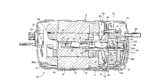
Fig. 1 is a longitudinal sectional view of
the compressor of the present inv~ntion in
operation; and
Fig. 2 is a end sectional view of the
compressor of the present invention.
Corresponding reference characters indicate
corresponding parts throughout the several views.
The exemplifications set out herein illustrate a ~-~
; ~, .
, .-
.. : . - :
- -. - ~ .
3 ~ ~
preferred embodiment of the invention, in one form
thereof, and such exemplifications are not to be
construed as limiting the scope of the invention
in any manner.
Referring to Fig. 1 thare is shc\wn the
horizontal compressor 10. A casing or housing 11
is shown having a cylindrical portion 12 and end
portions 14 and 16, respectively. A flange 1~ is
shown welded to cylindrical portion ~2 of
compressor 10. The flange 18 is usecl for mounting
the compressor to a refrigeration apparatus such
as an air conditioner or refrigerator.
A hermetic terminal 20 and cluster block 21
are provided for making electrical connections
from a supply of electric power to a compresso~
motor 38 located within housing 11. A discharge
tube 22 extends through end portion 16 and into
the interior of housing 12 as shown. Tube 22 is
sealingly connected to housing 11 as by soldering
or brazing. A suction tube 24 extends into the
interior of compressor housing 11 as shown in
Fig~ 2. Suction tube 24 connects to cylinder
block 52 by an O-ring 27 and by welding to housing
~1. An outer end of suction tube 24 is connected
to an accumulator 26 which has support plates 28
disposed thersin ~or supporting a ~iltering
mesh 29O
Compressor 10 is separated into substantially
two chambers, a motor chamber 30 and a compressor
unit chamber 32 by a partition means such as
pressure plate 34 disposed within housing 11.
Prassure plate 34 also separates an oil sump
located in housing 11 into oil sumps 37a and 37b.
As shown in Fig. 2, plate 34 is substantially
circular.
5~ ~ ~
Pressure plate 34 defines at least one
opening 36 communicating between charnbers 30 and
32. This opening 36 is created by a clearance
space between inner wall 13 of portion 12 and the
oukar diameter of plate 34. The clearance may be
further enlarged by a flat 35 or other similar
means cut into the outer diameter of plate 34
(Fig. 2). Oil sumps 37a and 37b are located in
the bottom of chambers 30 and 32 respectivelyl
communicating through opening 3~ along the lower
side of cylindrical portion 12. Each oil sump 37a
and 37b includes an oil level 41a and 41b
respectively. Opening 36 is disposed between oil
sumps 37a and 37b.
The opening 36 permits a limited amount of
refrigerant from chamber 30 through to chamber 32
while creating a tortuous path for the
refrigerant. This path helps to remove entrained
oil within the refrigerant. Opening 36 also
equalizes compressor pressures between motor
chamber 30 and compressor unit chamber 32 during
compressor shut down.
An electric motor 38 is disposed within motor
chamber 30 and includes a stator 40 and a rotor
42. Electric motor 38 is an induction type motor
having a squirrel cage rotor 42. Windings 44
provide the rotating magnetic field for inducing
rotational movement of rotor 42. The stator 40 is
secured by an interference fit ko the interior
wall of housing 11 as by shrink fitting. Th~rs is
an oil passage between the outer diameter of the
motor 38 and housing 11 to permit movement of oil
past motor 38 for cooling purposes.
Compressor unit 45 is disposed within chamber
32. A crankshaft 46 is secured in the hollow
interior aperture 48 of rotor 42. Crankshaft 46, `
. . ~ . .
.
2~3~
having an interior oil passageway 47, extends
axially through compressor unit 45, main bearing
50, and cylinder block 52 into an outboard bearing
54. On one end 49 of crankshaft 46, interior oil
passageway 47 is sealed by a pluq 51. The
crankshaft 46 is journalled for rotation within
bearings 50 and 54. Main bearing 50 includes
three flanges 60 thereon for securing bearing 50
to housing 11 at points 62 such as by welding
(Fig. 2~.
Cylinder 52 and outboard bearing 5~ are
secured to main bearing 50 by means of six bolts
66 as best illustrated in Fig. 2. Bolts 66 extend
through holes 68 in main bearing 50 and holes 70
in cylinder block 52 and are threaded into
outboard bearing 54 (Fig. 1).
As illustrated in Fig. 2, cranksha~t 46
includes an eccentric portion 74 thereon revolving
eccentrically around the axis of crankshaft 46. A
cylindrical roller member 76 surrounds eccentric
74 and rolls around eccentric portion 74 within
cylinder block 52. As shown in Fig. 1, a
counterweight 77 for counterbalancing the
eccentric 74 is secured to end ring 78 of motor
rotor 42, such as by riveting. A rectangular
sliding vane 80 is received in a vane slot 82
(Fiy. 2)o Vane slot 82 is located in cylinder
block 52~ A spring 84 biases an end of vane 80
against roller 7Ç for continuous engagement
therewith. Spring 84 is received in a spring
pocket 86 machined into the wall of cylinder block
52 adjacent vane slot 82. A discharge port 87
permits passage of compressed refrigerant from
cylinder 52 into motor chamber 30.
An oil passage 94 is provided adjacent vane
slot 82 for lubricating vane 800 A radial oil
'
.
'2 ~
lubrication hole 96 is provided in eccentric 74 of
shaft 46 for lubricating roller 76. The hole 96
communicates with bore 92 in shaft 4~ and receives
oil therefrom.
The oiling system of the present invention
comprises, in addition to pressure plate 34, a
bearing cap 100 attached over outboard bearing 54
connected to an oil pick-up passageway or tube
102. Oil pick-up tube 102 includes one end 104
disposed within oil sump 37b and the other end 105
opening into bearing cap 100. Tube opening 104 is
adjacent pressure plate opening 36, between motor
chamber 30 and compressor chamber 32. Oil pick-
up tube 102 can conduct oil from oil sump 37b
through end 104 into bearing cap and into contact
with crankshaft 46 and outboard bearing 54.
Because of the improvement to oil flow through the
compressor, the oil flow must be conkrolled or
restrained. To prevent excessi~e oil flow, it is
necessary to plug the motor end 49 of shaft 46
with a plug 51 and place a vent 53 at the end of
the main bearing ~0 in the outer diameter of shaft
46.
In operation, as power is applied to electric
motor 38, compressor unit 45 compresses
refrigerant due to the operation of rotor 76 and
vane 80 within cylinder 52. Compressed
refrigerant passes through discharge port 87 into
motor chamber 30. This creates a pressura ~
differential across plate 34, since compressor ~ -
chamber 32 is not pressurized by discharge gases.
High pressure within motor chamber 30 applies
pressure to the oil in sump 37a located within
motor chamber 30 and this ~orces oil past opening
36 into compressor unit chamber 32. This transfer
of oil lowers the sump oil level 41a within motor
2~3~ :
chamber 30 and raises the sump oil level 41b
within compressor unit chamber 32. q'he movement
of oil bore 9? during compressor operation, causes
oil to bs pumped up through oil passageway 102.
Oil level 41b within the compressor chamber 32
will preferably rise to a level to cover the open
end 104 of oil pickup tube. Additionally, the oil
level 41b may rise to a level equal to the center
line of the crankshaft 46.
The oil transported through pressure plate
opening 36 also flows into oil pick-up tube 102.
Oil is transported up oil pickup tube 102 into
bearing cap 100 by the oil level ~lb of oil in
sump 37b and by pumping caused by the movement of
oil bore 92. This oil is now in contact with
outer bearing 54 and passes through bore 92 in
crankshaft 46 thereby communicating with oil
passage g6, vane 82 and rotor 76. Discharge gases
from compressor unit 45 make their way past
pressure plate 3~, through opening 36 into
compressor unit chamber 32, and then exit
compressor 10 through discharge tube 22 continuing
on to a refrigeration apparatus (not shown).
This oiling sy~tem eliminates the need for a
separate ~il pump mechanism. The path of
refrigerant past pressure plate 34 and through
opening 36, creates a tortuous path for suspended
oil droplets within the compressed refrigeration
gases that helps to remove oil droplets from the
refrigerant.
While this invention has been described as
having a preferred design, the present invention
can be further modified within the spirit and
scope of this disclosure. This application is
therefore intended to cover any variations, uses,
or adaptations of the invention using its general
g ~ ~
:11
principles. Further, this application is intended
to cover such departures from the present
disclosure as come within known or customary :~
prackice in the art to which this inv~ention
pertains and which fall within the limits of the : :
appended claims.
;