Note : Les descriptions sont présentées dans la langue officielle dans laquelle elles ont été soumises.
209149
Apx~ar;~.tus for Shear-Cutting a Stack of
Amorphous Steel Strip
11DT04863
Technical Field
This invention relates to apparatus for shear-cutting
a stack of thin strip: of amorphous steel.
Background
Amorphous steel~~ are extremely hard materials and
have presented considerable problems in shear-cutting
because of exce:~sive wear of the blades used for effecting
the shear-cutting. Such wear is characterized by the
blades either becoming dull or chipping or both as the
shear-cutting operations are repeated over and over again.
In U.S. Patent 4,942,798-Taub et al, assigned to the
assignee of the present invention there is disclosed and
claimed an improved form of shear-cutting apparatus that
is characterized by reduced blade-wear as compared to
prior shear-cutl~ing apparatus. Taub et al achieve their
improved result: by using a special design of the shearing
blades in which one or both of the blades has a negative
rake angle. The blade material used by Taub et al is
described in the patent as a conventional hard cutting
material, such as cemented tungsten carbide. Specific
materials disclosed a:re Carboloy Grades 895 and 883, which
are cemented tungsten carbides containing 6 percent
cobalt.
Taub et al. describe one series of tests with such
blades in which stacks of Allied-Signal Corporation's
Metglas 2605-S2 amorphous steely each stack containing 10
superposed strips, each strip about 0.001 inch thick, were
shear cut with the blades until a blade failure occurred.
Sixty thousand cuts of these 10-strip-thick stacks were
achieved before a blade failure occurred.
11DT04863
2
While these results are quite good compared to those
that had been achieved with prior shear-cutting apparatus,
it should be notE:d that if the number of amorphous steel
strips in each stack is increased to substantially greater
than ten, there :~s a substantial decrease in blade life.
For example, if the stack thickness is increased from ten
to fifteen strips, the number of cuts that can be achieved
before blade failure (using the blade design and blade
materials disclosed in the Taub et al patent) decreases to
an average of less than 10,000. There is a distinct need
for blades that can,. shear-cut amorphous steel stacks of
this increased th.ickne~as (i.e., 15 strips) with a greater
number of cuts before any blade failure occurs.
Summary
In carrying out my invention in one form, I provide
shear-cutting apparatus that comprises a pair of relatively
movable blades having a configuration and physical
relationship to each other substantially as disclosed in
the aforesaid Taub et al patent. But instead of using the
specific blade materials disclosed in the Taub et al
patent, I use for both of my blades a cemented carbide
cutting material that consists essentially of tungsten
carbide particles and cobalt particles compacted under high
pressure and sintered at a temperature exceeding the
melting point of the cobalt, the tungsten carbide particles
being of submicron size before compaction and the cobalt
constituting about 1.6 percent by weight of the cutting
material. I have been able to achieve with such blades
prior to any blade failure an average of about 35, 000 or
more cuts of a 15-strip-thick stack of the above-referenced
2605-S2 amorphous stee:L strip, each strip being about .001
inches in thicknsass.
2 0 914 9 8 11DT04863
3
BRIEF DESCRIPTION OF DRAWINGS
For a better under:atanding of the invention, reference
may be had to the. following detailed description taken in
connection with the accompanying drawings, wherein:
Fig. 1 is a cross-sectional view through the
blades of cutting apparatus used for shear-cutting a stack
of amorphous steel strips. Fig. 1 is taken along the line
1-1 of Fig. 2.
Fig. 2 is a :aide elevational view of one of the
blades of Fig. 1 taken along the line 2-2 of Fig. 1.
Fig. 3 is a schematic diagram of the cutting
apparatus including 'the blades of Fig. 1.
Fig. 4 is a cross-sectional view similar to that
of Fig. 1 excepi= showing a modified form of the lower
blade.
DETAI7~ED DESCRIPTION OF EMBODIMENTS
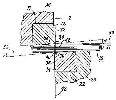
Referring nc~w to Fig. 1, there is shown a stack 10 of
amorphous steel strips 11 that is to be shear-cut by
apparatus compri:~ing two blades 12 and 14. Each of the
blades is of a special cemented carbide material soon to be
described in greater detail. The upper blade 12 is carried
by a steel block 16 that contains a notch 17 in which the
blade 12 is fitted and attached by a suitable bonding agent
to the block. T:he lower blade 14 is carried by a similar
steel block 20 that contains a notch 22 in which the blade
14 is f fitted and attached by a suitable bonding agent to
the block 20. In the' illustrated embodiment, the lower
block 20 is stationary and the upper block 16 is vertically
movable, but the invention in its broader aspects is not so
limited, e.g., both blocks could be movable, or the lower
block instead of the upper one could be movable.
The upper h~lade .L2 has two surfaces 30 and 32 which
are disposed transversely of each other and intersect at a
corner 34. The lower blade 14 likewise has two surfaces 36
11DT04863
4
and 38 which are disposed transversely of each other and
intersect at a corner 40.
Cutting of the stack 10 is effected along a
vertically-extending cutting plane 42 that extends
transversely of the sta~~k 10. The corners 34 and 40 of the
blades are located on opposite sides of this plane 42 and
in juxtaposition thereto. The blade surfaces 32 and 38
extend parallel to this cutting plane 42 and are also
located on opposite sides of the cutting plane and in
juxtaposition th~areto. Blade surfaces 32 and 38 are
located as close to the cutting plane 42 as reasonably
possible.
At the start of a cutting operation, the blades 12 and
14 are located at opposite sides of the stack 10, as shown
in Fig. 1. ThE~ blades are so positioned by suitable
conventional positioning and actuating means 45, shown in
block form in Fig. 3,, coupled to the upper block 16.
Cutting is effected by moving the upper blade downwardly so
that the corner ..4 moves downwardly toward corner 40 in a
direction parallel to the cutting plane. Such movement
first moves the stacl~: downwardly into engagement with
surface 36 of the lower blade and then bends the stack 10
slightly downward until the upper surface of the stack is
engaged by the lower ;surface 30 of the upper blade; and
then the upper corner 34 moves downwardly through the stack
and past the lower corner 40, shear-cutting the stack along
the cutting plane 42 :in the course of such downward motion.
This downward motion of the blade is effected by operating
the actuating means 45.
The work-engaging surface 30 of the upper blade 12 is
disposed at a negative rake angle with respect to a
reference plane 50 that extends through a point on its
corner 34 and is normal to the cutting plane 42 and also
normal_to the direction of movement of the upper blade 12.
2~~~4~g
11DT04863
In the illustrated embodiment, this reference plane 50 is
a horizontal plane.
Similarly, t:he work-engaging surface 36 of the lower
blade 14 is disposed at a negative rake angle with respect
to a reference plane 52 that extends through a point on its
corner 40 and is normal to the cutting plane 42 and also to
the direction of movement of the upper blade 12. In the
illustrated embodiment, this reference plane 52 is also a
horizontal plane.
The rake angle in a shear-cutting blade is considered
to be negative if the work-engaging surface (e.g. 30) is so
inclined as to make the corner (34) at the working edge of
the blade less sharp than it would be if the work-engaging
surface were locai:ed in the above-described reference plane
(50) .
In one embodiment of the invention, a negative rake
angle of 10 to 15 degrees is used on each of the blades 12
and 14. Additional discussion of the rake angle appears
hereinafter.
In the embodiment of Figs. 1 and 2, the upper blade 12
is also provided with a shear angle, which in the
illustrated form of tt-~e invention is about two degrees.
This shear angle is illustrated in Fig. 2 by the angle 60.
The shear angle is the angle, as viewed in cutting plane
42, that the corner of the blade makes with references
plane 50. By making this shear angle substantially greater
than zero, the corner a4 of the blade can be made to enter
the work more gradually along the length of the blade. In
the illustrated embodiment, the lower blade has a zero
degree shear ang7_e, or,, in effect, no shear angle.
It is important that the clearance between the
surfaces 38 and 32 of the blades be kept as small as
reasonably possible ands maintained at a substantially fixed
value during prolonged operation of the shear-cutting
machine. To this end, the supporting framework for the
209198
11DT04863
6
blades and the blade supporting blocks 16 and 20 should be
as stiff as feasible.. This supporting framework is
schematically illustrated in Fig. 3 at 70 and 72. Lower
framework portion 70 holds the lower blade-supporting block
70 stationary, and upper framework portion 72 guides the
upper block for vertical movement. In one embodiment, the
clearance between surfaces 38 and 32 is 0.0005 inches.
As pointed out in the Taub et al patent, the negative
rake angle present on the blades significantly contributes
to longer wear life for the blades. In the embodiment of
Figs. 1-3 a negat:lve rake angle is provided on both blades,
but benefits of a negative rake angle can be derived even
if only a single blade is provided with the negative rake
angle. In this letter arrangement, illustrated in Fig. 4,
the other blade is of a standard configuration, i.e., with
a zero degree rake angle.
According to the Taub et al patent, in order for
significant improvements in wear life of the blades to be
derived from the use of negative rake angles in a shear-
cutting applicat_'~on of this type, the sum of the rake
angles present in the two blades should be a negative value
of at least 5 degrees but no greater than about 35 degrees.
The higher the total negative rake angle, the greater is
the side thrust dE=velaped on the blades tending to separate
them during a cuti;.ing operation. Unless this separation is
limited to a very small value, the quality of the cut is
materially impaired. For this reason, the maximum total
negative rake angle should be about 35 degrees. A
preferred rake angle for the blades is a negative rake
angle of between 8 and 15 degrees for each blade.
As described in the aforesaid Taub et al patent, tests
to determine blade life were made by Taub et al with shear-
cutting apparatus corresponding to that disclosed
hereinabove except having blades made of cemented tungsten
carbide containing 6 percent cobalt (more specifically,
x~ .
11DT04863
7
with the top blade of Carboloy Grade 895 cemented tungsten
carbide and the bottom blade of Carboloy Grade 883 cemented
tungsten carbide). According to the Taub et al patent,
these tests werE: peri'ormed on substantially identical
stacks of amorphous steel strips, each stack containing l0
strips of Allied-Signal Corporations's Metglas 2605-S2
amorphous steel, ~=ach strip being about 3.3 inches wide and
about .001 inch thick. The stacks were formed by
effectively-continuous lengths of strip, superposed and
aligned, as illustrated. in Figs. 1 and 2. The superposed,
aligned strips were shear-cut along the plane 42 of Fig. 1,
following which the superposed strips were advanced a
predetermined distance along their length and again cut
along a corresponding plane 42. Such operations were
repeated over and over again until the cut quality as
determined by inspection became unacceptable, thus
indicating a blade failure. Each cut was performed by one
downward stroke o:E the upper blade through the entire stack
thickness, following which the blade was returned to its
position of Fig.. 1 i.n preparation for a new cutting
operation.
Taub details one series of tests on the above-
described 10-strip-thick stacks. In these tests, 6%-cobalt
cemented tungsten carbide blades 12 and 14 corresponding to
those illustrated and disclosed hereinabove, each having a
negative rake angle of 15 degrees, were used for the
cutting operations. (cane blade was of Carboloy Grade 895
and the other blade, of Carboloy Grade 883.) Sixty-
thousand (60,000) cuts were made with these blades before
a blade failure occurred.
While these results are quite good compared to those
that had been achieved with prior shear-cutting apparatus,
it should be noted that if the number of amorphous steel
strips. in each stack is. increased to substantially greater
than ten, there is a substantial decrease in blade life.
2 ~3 9 ~. 4 9 S 11DT04863
8
For example, if the stack thickness is increased from ten
to fifteen strips, the number of cuts that can be achieved
before blade failure (using the blade design and blade
materials disclosed in t:he Taub et al patent) decreases to
an average of less than 10,000.
I have been able t:o achieve without blade failure a
far greater number of cuts through 15-strip-thick stacks of
amorphous steel atrip by using shear-cutting apparatus
substantially as disclosed by Taub et al but differing in
the following important respect. Both of my blades instead
of being of the specific cutting materials used by Taub et
al in their above-described tests were of a cemented
tungsten carbide cutting material consisting essentially of
tungsten carbide :particles and cobalt particles compacted
under high pressure and sintered at a temperature exceeding
the melting point of the cobalt, the tungsten carbide
particles having an average size less than one micron and
the cobalt constituting' about 16 percent by weight of the
cutting material. Thins particular material is obtainable
from the manufacturer Fansteel Hydro Carbide, Latrobe,
Pennsylvania, as its HC-US16 cemented tungsten carbide.
According to the manufacturer's specification, the
composition of this material is 84 (~0.5) % tungsten
carbide and 16 (~0.5)% cobalt. Its Rockwell A hardness is
90.8 (~0.7); its density is 13.85 (~0.15) grams/cc; and its
transverse rupture strength is 500,000 pounds per square
inch minimum. The average particle size of its tungsten
carbide particles is 0 to 1 micron with some coarsen up to
4 microns. Tt is noted that the figures in parentheses are
variations from nominal values permitted by the
manufacturer's specification. In using the terms "about"
in the claims to define the percentage of a constituent
present in the blade material or to define the hardness,
density, or transverse rupture strength of the blade
f
11DT04863
9
material, I intend to comprehend values within the range
permitted by the~,e variations.
Using this particular cutting material (i.e., the HC-
US16) for both blades i.n the above-described shear-cutting
apparatus, I have been able to achieve without blade
failure an average of about 36,000 cuts through 15-strip-
thick stacks of amorphous steel strip, each strip about
.001 inches thick:.
These excellent results were considered to be quite
unexpected because other cobalt-containing cemented
tungsten carbide cutting materials differing from the HC-
US16 in ostensib:Ly minor respects demonstrated much lower
blade life in comparable tests. For example, using shear-
cutting apparatu:~ corresponding to that of Figs. 1-3 but
having one blade made of Fansteel Hydro Carbide's HC-US15
cemented carbide material and the other blade of the above-
described HC-US1~S material, I could effect an average of
only about 17,000 cuts through the 15-strip-thick stacks
prior to blade failure. This HC-US15 material, which is a
cemented tungsten carbide material containing 14% cobalt,
is described in more detail in Table I appearing
hereinafter. Performance of the HC-US15 cemented carbide
in the above.com~~ination, as well as in other combinations,
is described in '.Cable II appearing hereinafter.
As another example, using shear-cutting apparatus
corresponding to that of Figs. 1-3 but having both blades
made of Kennamet~~l K-94 cemented carbide material, I could
effect, on average, only about 4,000 cuts through the 15
strip-thick stacks prior to blade failure. This cutting
material, which is a cemented tungsten carbide material
containing 11. 5 o cobalt, is available from Kennametal, Inc,
Latrobe, Pennsylvania, and is described in more detail in
Table I al:~.:arimg hereinafter.
11DT04863
The following Table I summarizes properties of various
representative cobalt-containing cemented carbide cutting
materials that I hare studied to determine blade wear when used
in the apparatus of Figs. 1-3 for cutting 15-strip-thick stacks
of amorphous steel, each strip being about 0.001 inch thick.
TABLE I
Fansteel Fansteel
;nd: Carboloy Carboloy Kennametal Hydro CarbideHydro Carbide
Vt~ade: 883 895 K 94 HC-US15 HC-US16
WC (wt.%) 94% 94% 88.5% 86% 84%
Co (wt. 6 % 6 % 11. 14 % 16%
%) 5%
Hardness 91.7 to 92,5 to 89.8 89.8 908
(Rockw.A) 92.2 931
Density 15.0 15.0 14.20 14.15 13.85
(gm/cc)
Transverse
Rupture
Strength 290,000 260,000 380,000 425,000 500,000
(psi) (minimum)
Grain
Structure Medium F:W e/Med. Med./Coarse Submicron Submicron
(microns) 2.5 to 1.0 to 3.5 to 7.0 0 to 1 0 to 1
4.5 4.0
2 0 9 ~. 4 9 8 11DT04863
11
The following Table II shows representative blade-wear
performance of Table I materials when used for the blades of the
apparatus of Figs. 1-3 wizen cutting 15-strip-thick stacks of
amorphous steel, each strip being about 0.001 inch thick.
Table II
883* E~95* 883* K94* K94* K94*
Material 883 895 895 K94 883 895
Average
No. of Cuts
Before Blade
Failure 9,000 9,000 8,000 4,000 7,000 6,000
Lifetime
Set-ups** 11 ~ 6 211 3 5 4
Loose-Blade
Set-ups*** 2 0 8 0 1 1
HC-US15* HC-US15* HC-US15* HC-US16* HC-US16*
Material 883 ~ 8.95 HC-US16 883 HC-US16
Average
No. of. ~s
Before ulade
Failure 11,000 2:L,000 17,000**** 4,000 36,000
Lifetime
Set-ups** 6 1 2 1 276
Loose-Blade
Set-ups*** 1 0 1 0 37
Notes Re Table II:
1. *Designates that one blade was of the numerator material
and the other was oi_ the denominator material.
2. Average number of cuts has been rounded to the next
highest thousand.
3. **"Lifetime Set-ups" denotes the total number of set-ups
for a particular cutting material combination in which the number
of cuts was counted..
4. Where the set-ups for a particular cutting material
combination have be<:n car:ried out on a plurality of cutting
11DT04863
12
machines, a figure representing the average number of cuts
has been determined for each such machine, and these
figures have beE;n averaged together to establish the
"Average No. of Cuts Before Blade Failure" shown in Table
II.
5, ***"Loose-Blades Set-ups" denotes set-ups in which
cutting was terminated because one of the blades became
loose or fell completely off. The results of such set ups
have not been included :in calculating the average number of
cuts unless such blade-loosening or fall-off occurred at a
higher figure than the "Average No. of Cuts Before Blade
Failure" for all "Lifetime Set-ups" for a particular
cutting material combination in the same shear-cutting
machine.
6. The figures for the HC-US16/HC-US16 combination are
derived from commercial production data over a 9-month
period. 7. ****This figure is based upon two set-ups. In
one, cutting wa:~ term,inated when the blade loosened at
27,658 cuts. Ire the other, blade failure occurred at a
maximum of 6, 000 cuts.
~ze kting operations, referred to in the above Table
II, were all pe~rforme~d with shear-cutting apparatus of
substantially the form illustrated in Fig. 1-3 herein.
It will be apparent from Table II that a far greater
number of cuts were achieved with both blades being of the
16% cobalt cutting material of the last column than with
any of the other materials. I am unable to fully explain
the reasons for i:he exceptional performance of this cutting
material, but the high transverse rupture strength of the
material, which is a measure of its toughness and, hence,
its ability to resist chipping, is considered to be a
significant contributing factor. This high transverse
rupture strength is made possible by the relatively high
percentage of cobalt present in the material, and the high
percentage of cobalt is achievable without unduly
11DT04863
13
diminishing the i:ungsten carbide content because of the
very small average size of the tungsten carbide particles,
i.e., submicron, or 0 to 1 micron. Tungsten carbide is the
very hard component relied upon for cutting, and its
content must be kept high to achieve effective cutting
without undue dul_Ling, or loss of sharpness, of the blades.
In referring hereW above to "chipping" , I mean the loss, or
pull-out, of particles from the cutting edge of the blades
during the cuttin~~ operations.
While Table II above shows that the "Average No. of
Cuts Before Blade Failure" was about 36,000 where both
blades were of the 16% cobalt material (HC-US16), it is
noteworthy that some of the shear-cutting machines on which
this data was obtained achieved much higher averages over
prolonged periods of commercial production. For example,
over one three-month period of commercial production, 20%
of these shear-cutting machines averaged about 90,000 cuts
and an additional 33% of these machines averaged about
60,000 cuts, all without blade failure, using the 16%
cobalt material (HC-US16) for both blades.
In the illustrated embodiments, each of the blades is
attached to its supporting block by a thin layer of
adhesive applied i~o careafully machined and cleaned surfaces
of the block and the blade and immediately thereafter
scrubbed into place by gently rubbing the juxtaposed blade
surface on the supporting surface. Thereafter, clamping
pressure is applied to the blade while the adhesive dries
and cures. An a~3vantage of using an adhesive instead of
brazing for attaclning t:he blade is that the joining process
involves no heat that can set up undesirable stresses in
the blade due to the different coefficients of thermal
expansion between the blade material and the block
material. Such ~ctressEa can cause a premature failure of
the joint between the blade and its supporting block.
Another advantage of 'the adhesive over brazing is that the
t":
11DT04863
14
blade can be more easily detached from the block when it is
time to replace the blade. In one embodiment, the adhesive
used is one avai7_able: from Loctite Corp. , Newington, CT,
as its Loctite 324 adhesive. This adhesive is applied
after a suitable activator, such as Loctite 70715, is
applied to the unc~erlyi:ng surface, preferably by spraying.
While I have shown and described a particular
embodiment of my invention, it will be obvious to those
skilled in the art that: various changes and modifications
may be made without departing from the invention in its
broader aspects; and I, therefore, intend herein to cover
all such changes ~3nd modifications as fall within the true
spirit and scope ~~f my invention.