Note : Les descriptions sont présentées dans la langue officielle dans laquelle elles ont été soumises.
y
PATENT
MULTI-LAYER ABSORBENT COMPOSITE
Background of the Invention
Field of the Invention
The present invention relates to an absorbent composite, particularly
to an absorbent composite which is useful in personal care products.
Description of the Related Art
Personal care products fo,r the absorption of body fluids are known.
Such products include adult incontinence_ products, diapers, training
pants, feminine care products, wound dressings and the like. As a
general rule, such personal care products generally comprise an
amount of a cellulosic fiber such as wood pulp fluff. Wood pulp
fluff is known to be a suitable absorbent for body fluids. As a
general rule, 1 gram of wood pulp fluff is able to absorb from about
5 to about 8 grams of a discharged body fluid such as urine. A
personal care product such as an infant diaper, generally has an
absorbent capacity of at least about 200 to 400 grams of urine.
Thus, when such an infant diaper is formed from wood pulp fluff, a
relatively large quantity of wood pulp fluff must be employed.
In order to reduce the amount of wood pulp fluff and the
corresponding bulk of such an infant diaper, it is known to include
high absorbency materials known in the art as superabsorbents. Such
high absorbency materials are generally capable of absorbing at least
about 10, preferably at least about 20, and up to 50 or more times
their weight in water. By incorporating such high absorbency
-1-
~~'~f~"?'E.'r: -.,
7V ~~ ~ Peg ~~ '\7 ;
materials in infant diapers, it is possible to reduce the overall
bulk of the diaper while maintaining its absolute absorbent capacity.
Nonetheless, the use of such high absorbency materials is not without
problems. For example, some high absorbency materials are known to
cause gel blocking. That is, as the high absorbency materials become
swollen with a liquid, they form a gelatinous mass which prevents the
free flow of liquid therethrough. Thus, while the high absorbency
materials may be able to absorb an initial insult, subsequent insults
are unable to pass through the now swollen high absorbency material.
As a result, subsequent insults tend to pool and run off of the
absorbent product.
Accordingly, a number of different structures have been proposed to
alleviate or reduce the problems associated with incorporating high
absorbency materials in personal care products.
U.S. Patent 4,699,619 issued October 13, 1987, to Bernardin describes
a multilayer absorbent composite having a first relatively low
density layer and a second relatively high density layer underlying
at least a portion of the first layer. A high absorbency material
(superabsorbent) is described as being located between said first and
second layers.
U.S. Patent 4,102,340 issued July 25, 1978, to Mesek et al. is
directed to a disposable article with a particulate hydrophilic
polymer in an absorbent bed. Described is an absorbent pad
comprising a fibrous structure having an intermediate densified layer
and a layer of highly porous, loosely compacted batt on both sides of
the densified layer. One of the batt layers is described as
including a particulate, water-insoluble but water-swellable
polymeric absorbent.
U.S, patent 4,269,188 issued May 26, 1981, to Nishizawa et al. is
directed to a disposable diaper. Disclosed is a disposable diaper
including an absorbent material comprising a laminate wherein a
water-absorbent polymer powder is fixed between two sheets of paper.
_2_
! r
C is~~ c~(!'"2:~
A fl uff pul p l ayer i s l ocated on both sides ~ ~R'e'dl aro ate
containing a water-absorbing polymer.
While the structures described in the. referenced patents have often
proven beneficial, they have not completely solved the problems
associated with the use of high-absorbency materials.
In use, the wood pulp fluff generally serves to quickly absorb a
discharged body fluid. The fluid is generally held in the pores of
the fluff matrix. The high absorbency material in the fluff matrix
then absorbs the fluid and, in effect, dewaters the fluff matrix.
That is, the fluff serves to absorb and hold surges (relatively large
quantities applied relatively quickly) of body fluid until the high-
absorbency material can absorb the body fluid. Moreover, many known
personal care products employ high-absorbency materials in relatively
low quantities. This is because the cost of such high-absorbency
materials is generally greater than the cost of a material such as
wood pulp fluff. It is sometimes desirable to employ a relatively
high concentration of high-absorbency material when forming a
personal care product. As the concentration of high-absorbency
material increases in an absorbent product, the concentration of wood
pulp fluff generally decreases. The high-absorbency materials are
not generally able to absorb urine at the rate at which it is
applied. This may lead to leakage in absorbent structures having
high concentrations of absorbent materials.
It is desired to provide an absorbent structure which may contain an
absorbent layer having a relatively high concentration of
high-absorbency material but which absorbent structure is capable of
quickly absorbing body fluids applied thereto.
Summary of the Invention
The present invention concerns an absorbent structure. The structure
comprises a first surge management layer, a second surge management
layer, and an absorbent layer located between the first and second
surge management layers. The first surge management layer comprises
a fibrous web comprising synthetic polymeric fibers. The first surge
management layer has a basis weight of from about 20 to about
-3-
~,~~~?~f~':~
200 grams per square meter and a density of from about 0.01 to about
0.12 gram per cubic centimeter. The second surge management layer
comprises a fibrous web comprising hydrophilic fibers. The second
surge management layer has a basis weight of from about 20 to about
200 grams per square meter and a density of from about 0.04 to about
0.20 gram per cubic centimeter. The absorbent layer comprises means
for containing a high-absorbency material and from about 50 to about
100 weight percent, based on total weight of the absorbent layer, of
a high-absorbency material contained by said means for containing a
high-absorbency material. The absorbent layer has a basis weight of
from about 200 to about 1000 grams per square meter and a density of
from about 0.06 to about 0.40 gram per cubic centimeter. The density
of the absorbent layer is greater than the density of the first and
second surge management layer and the density of the first surge
management layer is different than the density of the second surge
management layer.
Brief Description of the Drawin4s
Fig. 1 is a cross-sectional view of an absorbent structure according
to the present invention.
Fig. 2 is an exploded view of an infant diaper incorporating an
absorbent structure according to the present invention.
Fig. 3 is a cross-sectional view of one embodiment of an absorbent
layer of the present invention.
Fig. 4 illustrates the apparatus for determining the Absorbency Under
Load values of a high-absorbency material.
Fig. 5 is a perspective view of the apparatus used in conducting the
fluid run-off determination.
Fig. 6 is a cross-sectional view of the apparatus used in conducting
the fluid run-off determination.
-4-
p\ r
~~'~~4~~
Fig. 7 graphically illustrates the results set forth in Table 1.
Fig. 8 graphically illustrates the results set forth in Table 2.
Detailed Description of the Invention
The present invention concerns an absorbent composite. The absorbent
composite comprises first and second surge management layers and an
absorbent layer located between the first and second surge management
layers.
The first surge management layer comprises a fibrous web. The
fibrous web comprises synthetic polymeric fibers. The synthetic
polymeric fibers may be formed from any polymeric material capable of
forming fibers which fibers can be formed into a fibrous web
possessing the properties of the first surge management layer as
discussed herein. Suitable polymeric material from which the
synthetic polymeric fibers of the first surge management layer may be
formed include polyolefins, such as polyethylene, polypropylene, and
the like; polyesters such as polyethylene terephthalate and the like;
polyamides such as nylon 6, nylon 6,6,
poly(iminocarboxylpentamethylene) and the like; acrylics, and
modified cellulosic material, such as cellulose acetate; as well as
mixtures and copolymers thereof.
The synthetic polymeric fibers may be formed by meltblowing, through
a spunbond process, by extrusion and drawing, or other wet, dry and
melt spinning methods known to those skilled in the art. The
synthetic polymeric fibers from which the first. surge management
layer is formed may have a discrete length or may be substantially
continuous. For example, if the synthetic polymeric fibers are
formed by meltblowing, the fibers may be substantially continuous
(few visible ends). If the fibers are formed by extrusion and
drawing to produce a tow, the tow may be used as produced or cut into
staple fibers having a length, for example, of from about
25 millimeters to about 75 millimeters or short cut into lengths of
from about 1 millimeter to about 25 millimeters. The synthetic
polymeric fibers may suitably have a maximum cross-sectional
dimension of from about 0.5 micrometer to about 50 micrometers as
-5-
~~~~G
determined by microscopic measurement using an optical microscope and
a calibrated stage micrometer or by measurement from Scanning
Electron photomicrographs.
The fibrous webs may be formed directly through a spunbond or
meltblown process, or by carding or air-laying staple or short cut
fibers. Other methods of forming fibrous webs known to those skilled
in the art may be suited for use in the present invention. The web
may subsequently be bonded to enhance structural integrity. Methods
of bonding fibrous webs are known to those skilled in the art and
include thermal bonding, point bonding, powder bonding, ultrasonic
bonding, chemical bonding, mechanical entanglement, and the like.
The fibers may be homogenous fibers or may be a core/sheath or side-
by-side fibers known to those skilled in the art as bicomponent
fibers.
The first surge management layer may be formed from a single type of
synthetic polymeric fiber or may contain synthetic polymeric fibers
formed from different polymeric materials, having different fiber
lengths or maximum cross-sectional dimensions. For example, the
first surge management layer may comprise a mixture of
(1) bicomponent fibers having a polyethylene sheath and a
polypropylene core which bicomponent fibers have a maximum cross-
sectional dimension of about 20 micrometers and a length of about
38 millimeters and (2) polyester fibers (polyethylene terephthalate)
having a maximum cross-sectional dimension of about 25 micrometers
and a length of about 38 millimeters. Fibers 1 and 2 may be combined
in a weight ratio of from 1:99 to 99:1. The fibers may be uniformly
mixed or may be concentrated at opposite planar surfaces of the first
surge management layer.
The first surge management layer of the present invention suitably
comprises from about 10 to 100 weight percent, beneficially of from
about 20 to 100 weight percent, preferably of from about 25 to 100
weight percent, and most preferably of from about 50 to 100 weight
percent synthetic polymeric fibers. In addition to the synthetic
polymeric fibers, the first surge management layer may contain from
-6-
about 90 to 0 weight percent of a nonsynthetic polymeric fiber such
as wood pulp fluff cotton linters, cotton, and the like.
In one preferred embodiment, the first surge management material
contains synthetic polymeric fibers which are formed from a polymeric
material having a high wet modulus. The importance of the modulus of
a material is discussed in the book "Absorbency" edited by P.K.
Chatterjee (Elsevier, New York, 1985). A polymeric material will be
considered to have a high wet modulus when it has a wet modulus
greater than about 80 percent of its dry modulus as determined by
ASTM (American Society for Testing and Materials) test method
D 2101-91 using modified gauge lengths. It is often desired to form
the synthetic polymeric fibers of the first surge management material
from a polymeric material having a high wet modulus because such
materials generally form fibrous webs which possess a relatively high
degree of wet resiliency. The wet resilience of a fibrous web is
related to the pore structure (while under a load) of the fibrous
web. As will be discussed in greater detail below, it is often
desired that the first surge management layer have a relatively high
degree of wet resilience.
The pore structure (while under a load) of a fibrous structure formed
from fibers of a polymeric material will, as discussed above, relate
to the wet and/or dry modulus of the constituent fibers. Wet modulus
of the constituent fibers should be considered for fibers that may
likely be wetted during use. For the purposes of estimating the
effect of load on the pore structure of a fibrous structure formed
from fibers of a polymeric material the tensile modulus of the fiber
which can be related to the flexural rigidity of the fiber as shown
in the book "Physical Properties of Textile Fibers" by W. E. Morton
and J. W. S. Hearl (The Textile Institute, London, 1975) can be used.
As a general rule, the polymeric materials from which the synthetic
polymeric fibers of the first surge management layer are formed will
be inherently hydrophobic. As used herein, the term "hydrophobic"
describes a material which has a contact angle of water-in-air of
_7_
~~~~~G~v
greater than 90 degrees. The term "hydrophilic" refers to a material
which has a water-in-air contact angle of less than 90 degrees. The
water-in-air contact angle is suitably determined as set forth in the
book "Absorbency" edited by P.K. Chatterjee (Elsevier, New York,
1985). As used herein, a polymeric material will be considered to be
"inherently" hydrophobic or hydrophilic when the polymeric material,
free from any surface modifications or treatments, e.g., surface
active agents, spin finishes, blooming agents, etc., is hydrophobic
or hydrophilic, respectively.
'
iJhen the synthetic polymeric fibers of the first surge management
layer are formed from a polymeric material which is inherently
hydrophobic, it is often desirable to treat the fibers with a surface
modifying material to render the surface of the fiber hydrophilic.
For example, a surfactant may be applied to the fibers.
The first surge management material suitably has a basis weight of
from about 20 to about 200, beneficially of from about 30 to about
150, and preferably of from about 35 to about 125 grams per square
meter.
The first surge management material suitably has a density of from
about 0.01 to about 0.12, beneficially of from about 0.015 to about
0.1, and preferably of from about 0.02 to about 0.08 gram per cubic
centimeter.
The second surge management layer also comprises a fibrous web. The
fibrous web of the second surge management layer comprises
hydrophilic fibers. The hydrophilic materials may be inherently
hydrophilic such as cellulosic fibers such as wood pulp fluff, cotton
linters, and the like; regenerated cellulose fibers such as rayon; or
certain nylon copolymers such as poly(pentamethylenecarbonamide)
(nylon-6)/polyethylene oxide. Alternatively, the hydrophilic fibers
may be hydrophobic fibers which have been treated to possess a
hydrophilic surface. For example, the fibers may be formed from a
polyolefin material which is subsequently coated with a surface
active agent such that the fiber itself is hydrophilic as described
_g_
'~~~~Z~~
herein. Other methods of hydrophilizing fibers formed from
hydrophobic materials are known and suited for use in the present
invention.
Methods of providing inherently hydrophilic fibers such as wood pulp
fluff are known. So to are methods of providing regenerated
cellulosic fibers such as rayon. Hydrophobic fibers which can be
treated to possess a hydrophilic surface are suitably formed in the
same manner and from the same materials described above in connection
with the first surge management layer. If the hydrophilic fibers are
hydrophobic fibers which have been treated to possess a hydrophilic
surface, the fibers will suitably have a fiber length and maximum
cross-sectional dimension as set forth above. If the hydrophilic
fibers are inherently hydrophilic such as wood pulp fluff, rayon,
cotton, cotton linters and the like, the fibers will generally have a
length of from about 1.0 millimeters to about 50 millimeters and a
maximum cross-sectional dimension of from about 0.5 micrometers to
about 100 micrometers.
The fibrous web of the second surge management layer may be formed in
the same way as set forth above in connection with the first surge
management layer. The second surge management layer suitably
comprises from about 10 to 100 weight percent, beneficially from
about 30 to 100 weight percent, and preferably from about 55 to 100
weight percent of hydrophilic fibers, preferably inherently
hydrophilic fibers. In addition to the hydrophilic fibers, the
second surge management layer may contain from about 90 to 0 weight
percent of a high wet modulus, preferably inherently hydrophobic
fibers. The second surge management layer may be formed from a
single type of hydrophilic fiber or may contain hydrophilic fibers
having different compositions, lengths and maximum cross-sectional
dimensions. The second surge management layer suitably comprises a
greater percentage of inherently hydrophilic fibers than the first
surge management layer. Specifically, the second surge management
layer suitably comprises at least about 10, beneficially about 25 and
preferably about 50 weight percent more inherently hydrophilic fibers
- g ,
~'~~~,~t~~~
than the first surge management layer when the first surge management
layer comprises inherently hydrophilic fibers.
In one preferred embodiment, the second surge management layer is
formed from air laid cellulosic fibers such as wood pulp fluff. Wood
pulp fluff fibers are preferred for use due to their ready
availability and due to the fact that the fibers are relatively
inexpensive compared to synthetic polymeric fibers.
The second surge management layer suitably has a basis weight of from
about 20 to about 200, beneficially of from abaut 50 to about 150,
and preferably of from about 25 to about 125 grams per square meter.
The second surge management layer suitably has a density of from
about 0.04 to about 0.20, beneficially of from about 0.06 to about
0.16, and preferably of from about 0.08 to about 0.14 gram per cubic
centimeter.
An absorbent layer is located between the first and second surge
management layers. The absorbent layer is in liquid communication
with the first and second surge management layers. As used herein,
the absorbent layer will be considered to be in liquid communication
with the first and second surge management layers when a liquid can
move from either the first or second surge management layer into the
absorbent layer. It is not necessary that the first and second surge
management layers be in direct contact with the absorbent layer.
That is, additional intervening layers can appear between the surge
management layers and the absorbent layer. Nonetheless, a liquid
must be able to move from the first and second surge management
layers, through or around any such intervening layers and into the
absorbent layer. When this is possible, the first and second surge
management layers will be considered to be in liquid communication
with the absorbent layer.
The absorbent layer comprises means for containing a high-absorbency
material, and a high-absorbency material contained by such means for
containing a high-absorbency material. The high-absorbency material
- 10
is present in the absorbent structure in an amount of from about 50
to about 100, preferably of from about 60 to about 95, and most
preferably of from about 70 to about 90 weight percent based on total
weight of the absorbent layer.
Means of containing high-absorbency materials are known to those
skilled in the art. For example, the means for containing the
high-absorbency material may comprise a fibrous web, a porous sponge-
like material, a substrate to which the high-absorbency material is
attached or adhered, multiple sheets of material between which the
high-absorbency material is located, and the like. Any means of
containing of the high-absorbency material is suited for use in the
present invention.
As used herein, the term "high-absorbency material" refers to a
water-swellable, generally water-insoluble material capable of
absorbing at least about 10, desirably about 20, and preferably about
50 times or more its weight in water. The high-absorbency material
may be formed from organic material, which may include natural
materials such as agar, pectin, and guar gum, as well as synthetic
materials such as synthetic hydrogel polymers. Synthetic hydrogel
polymers include, for example, carboxymethyl cellulose, alkali metal
salts of polyacrylic acid, polyacrylamides, polyvinyl alcohol,
ethylene malefic anhydride copolymers, polyvinyl ethers, hydroxypropyl
cellulose, polyvinyl morpholinone, polymers and copolymers of vinyl
sulfonic acid, polyacrylates, polyacrylamides, polyvinyl pyrridine,
and the like. Other suitable polymers include hydrolyzed
acrylonitrile grafted starch, acrylic acid grafted starch, and
isobutylene malefic anhydride copolymers and mixtures thereof. The
hydrogel polymers are preferably lightly cross7inked to render the
materials substantially water insoluble. Crosslinking may, for
example, be by irradiation or covalent, ionic, van der Waals, or
hydrogen bonding. Suitable materials are available from various
commercial vendors such as the Dow Chemical Company, Hoechst Celanese
Corporation, Allied Colloid Inc., and Stockhausen Inc.
- 11 -
s
The high-absorbency material may be in the form of particles,
spheres, flakes, fibers, rods, films or any of a number of geometric
forms. When in the form of particles or spheres, it may be desired
that the particles or spheres have a maximum cross-sectional
dimension of from about 10 micrometers to about 2000 micrometers,
preferably from about 60 micrometers to about 1000 micrometers.
In one embodiment it is desired that the high-absorbency material
have the ability to absorb a liquid while under a load. The ability
of a high-absorbency material to absorb a liquid while under a load
is quantified as the Absorbency Under Load (AUL) value.
Specifically, the AUL value is the amount (in grams) of an aqueous
solution containing 0.9 weight percent sodium chloride, a gram of the
high-absorbency material can absorb in 60 minutes under a load of
0.3 pound per square inch. As a general rule, it is desired that the
high-absorbency material have an AUL value of at least about 10,
desirably at least about 15, and preferably at least about 25. A
method by which the absorbency under load value is determined is set
forth below in connection with the Examples.
The absorbent layer suitably has a basis weight of from about 200 to
about 1000, beneficially of from about 250 to about 750, and
preferably of from about 300 to about 500 grams per square meter.
The absorbent layer suitably has a density of from about 0.06 to
about 0.40, beneficially of from about 0.12 to about 0.35, and most
preferably of from about 0.15 to about 0.30 gram per cubic
centimeter.
The density of the absorbent layer is greater than the density of
both the first surge management layer and the second surge management
layer. Suitably, the density of the absorbent layer is at least
about 20 percent, beneficially at least about 30 percent, and
preferably at least about 40 percent greater than the density of both
the first and second surge management layers. Further, the densities
of both the first and second surge management layers are different.
It is preferred that the densities of the first and second surge
- 12 -
CA 02092605 2000-06-19
management layers differ by at least about 20 percent of the lowest
density layer.
The absorbent structures of the present invention comprise at least
three layers. From the above, it is clear that the three layers of
the absorbent structures of the present invention all have a
different density. Further, the absorbent layer has the highest
density of the three. Of the remaining two layers, the first and
second surge management layers, one will have an intermediate density
(relative to the absorbent layer and other surge management layer)
and one will have a low density compared to the other surge
management layer and absorbent layer. The absorbent layer is located
between the first and second surge management layers. Thus, the
density of the various layers of the absorbent structure according to
the present invention will be arranged in one of the following
orders: lowest density, highest density, intermediate density; or
intermediate density, highest density, lowest density.
For the purpose of this application, density of the first surge
management layer, second surge management layer and absorbent layer
refers to an average density of the layer being tested. That is, a
representative number of density measurements are taken across the
length and width of the layer being tested. The individual density
measurements are then averaged to determine the average density. The
density is determined under a load of 0.05 pound per square inch
(350 pascal).
The absorbent structures according to the present invention are
suitable for use in disposable absorbent products such as diapers,
training pants, adult incontinence products, feminine care products,
wound dressings and the like. Methods of forming such absorbent
products and the absorbent products formed thereby are known to those
skilled in the art and are described, for example, in the following
U.S. patents: 4,944,735 issued July 31, 1990 to Mokry;
4,798,603 issued January 17, 1989, to Meyer et al.; 4,710,187 issued
December 1, 1987, to Boland et al.; 4,770,656 issued~September 13,
1988, to Proxmire et al.; and 4,762,521 issued August 9, 1988, to
Roessler et al.; as well as co-pending Canadian Patent
- 13 -
CA 02092605 2000-06-19
Application Serial Nos. 2,060,743 and 2,060,744, both filed
February 5, 1992.
The absorbent structures of the present invention suitably form the
absorbent core of the disposable absorbent products. Such an
absorbent core is suitably sandwiched between a bodyside liner, and a
liquid impervious outer cover. Thus, in use, one of the surge
management layers may be located between the body of the wearer and
the absorbent layer, while the other surge management layer will be
located such that the absorbent layer is between it and the body of
the wearer. Either the first or second surge management layer can be
located on the bodyside of the absorbent layer (between the absorbent
layer and the body of the wearer during use).
In one embodiment of the present invention the first surge management
layer is located, during use, between the absorbent layer and the
body of the wearer. In this embodiment, the first surge management
layer comprises from about 10 to about 100 weight percent of a
synthetic polymeric fiber formed from a high wet modulus polymeric
material. The web is formed such that it possesses a relatively high
degree of structural integrity. For example, the web can be formed
by meltblowing or may be a bonded carded web. Such materials may
generally possess a relatively high degree of wet resiliency. When
the first surge management layer is resilient, the fibrous web is
able to maintain an open porous structure while under a load, and to
resist collapse when wetted, such that it is able to receive
subsequent insults.
Specifically, in one preferred embodiment, it is desired that the
surge management layer located between the body of a wearer and the
absorbent layer exhibits a wet resiliency factor of at least about
1.5, preferably of at least about 1.7. The wet resiliency factor is
determined by compressing a wet sample of the surge management layer
at a pressure of 2.0 pounds per square inch for 60 minutes and then
measuring the density at the 2.0 pounds per square inch
- 14 -
~~~~~~r:~
(13.19 kilopascal) loading. The sample is then measured for density
at a loading of 0.2 pound per square inch. The wet resiliency factor
is determined by dividing the sample density at 2.0 psi by the sample
density at 0.2 psi.
When the second surge management layer is formed from more than
50 weight percent of inherently hydrophilic fibers such as wood pulp
fluff, the second surge management layer may be less resilient than
the first surge management material comprising synthetic polymeric
fibers. When the second surge management layer is formed entirely
from wood pulp fluff, the second surge management layer possesses a
relatively low degree of wet resiliency.
Accordingly, in one embodiment of the present invention, the first
surge management layer is located between the body of a wearer and
the absorbent layer and comprises at least about 50 weight percent of
a synthetic polymeric fiber. The second surge management layer is
located on the opposite side of the absorbent layer and comprises at
least about 55 weight percent of a cellulosic fiber such as wood pulp
fluff. Both the first and second surge management layers function by
holding surges of liquid applied to the absorbent structure for a
period of time sufficient for the absorbent layer to desorb the surge
management layers and absorb and retain the liquid. In this manner,
the surge management layers are able to receive subsequent insults of
liquid (surges) and again hold the liquid for a period of time
sufficient for the liquid to be absorbed by the absorbent layer.
A further advantage of locating the first surge management layer
between the body of a wearer and the absorbent layer is that the
first surge management material, may have a relatively dry feel even
after it has been wetted. This is because the first surge management
layer includes synthetic polymeric fibers, is resilient and may be
more easily desorbed by the absorbent layer than the second surge
management layer. Thus, a relatively dry surface may be presented
for contacting a wearer's skin. In contrast, the second surge
management layer including cellulosic or other inherently hydrophilic
fibers can have a relatively wet feel. This wet surface is located
15 -
~~eJ~Nxiti~..~
remote from the body of a wearer and is spaced therefrom by the first
surge management layer and the absorbent layer.
In order to assist the second surge management layer in performing
its surge management function when it is located with the absorbent
layer and first surge management layer between it and the body of a
wearer, it may be desired to provide a liquid applied to the first
surge management layer easy access to the second surge management
layer. Accordingly, it may be desired to provide the absorbent layer
and/or first surge management layer with areas of reduced basis
weight or holes so that a liquid applied to the first surge
management layer can pass through the areas of lower basis weight or
the holes quickly and reach the second surge management layer.
Alternatively, it may be desired to make the first surge management
layer and/or absorbent layer smaller than the second surge management
layer so that if a liquid applied to the first surge management layer
and/or absorbent layer runs off of that layer, it then comes into
contact with the second surge management layer which is either wider
and/or longer than the first surge management layer or the absorbent
layer. It may also be possible to form the first surge management
layer and the absorbent layer with a low mass such that a liquid
applied to the first surge management layer can pass through the
first surge management layer and absorbent layer without complete
dissipation of kinetic energy. For example, the absorbent layer can
be formed to have large free volume pathways in which free volume is
maintained even after initial wetting.
In one preferred embodiment, the absorbent layer is formed from an
air-laid mixture of wood pulp fluff and high-absorbency material.
The high-absorbency material is contained in the air-laid wood pulp
fluff. The mixture of wood pulp fluff and high-absorbency material
is suitably air-laid onto a porous forming surface through which a
vacuum is drawn. The.porous forming surface may be a forming wire or
forming drum. In order to form holes or areas of reduced basis
weight in the absorbent layer, areas of the porous forming surface
are blocked off so that a vacuum is not drawn therethrough. These
blocked off areas correspond to the areas of reduced basis weight or
- 16 -
f
holes in the absorbent layer. The blocked off areas can be arranged
in essentially any pattern desired. In one embodiment, the blocked
off areas are blocked off by 3-dimensional projections. For example,
the areas may be blocked off by pyramidal or conically shaped
projections. Alternatively, holes may be cut in the absorbent layer
by methods known to those skilled in the art.
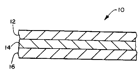
The present invention can be understood by reference to the drawings
wherein Fig. 1 illustrates a cross-sectional view of the absorbent
structure according to the present invention. Absorbent structure 10
comprises a first surge management layer 12, an absorbent layer 14
and a second surge management layer 16. The absorbent layer 14 is
located between the first surge management layer 12 and the second
surge management layer 16.
As discussed above, the absorbent structures according to the present
invention are suitable for use in absorbent products such as diapers.
Fig. 2 illustrates an infant diaper embodying an absorbent structure
according to the present invention. Diaper 20 typically includes a
liquid-permeable bodyside liner 22; a substantially
liquid-impermeable outer cover 24; an absorbent structure 26,
positioned between the liner and outer cover; leg elastic members 28;
and waist elastic members 30. The liner 22, outer cover 24,
absorbent structure 26, and the elastic members 28 and 30 may be
assembled in a variety of well-known diaper configurations. It
should be recognized, however, that in articles other than diapers,
individual components, such as the liner, outer cover, or elastic
members, may be optional. The desirability of including particular
components in other absorbent articles would depend on the intended
end use of the absorbent article.
The absorbent structure 26 comprises a first surge management layer
32, a second surge management layer 34, and an absorbent layer 36
located between the surge management layers 32 and 34. As can be
seen from reference to Fig. 2 in the illustrated embodiment, the
second surge management layer 34 is larger than the absorbent layer
36 and the first surge management layer 32. Thus, if a liquid cannot
- 17 -
be held or absorbed by the first surge management layer 32 or rapidly
absorbed by the absorbent layer 36, and the liquid runs off, it will
come into contact with the second surge management layer 34 and be
maintained in the absorbent structure. The diaper illustrated in
Fig. 2 further comprises containment flaps 38 known to those skilled
in the art and adhesive tape members 40 for attaching the diaper
about the waist of an infant.
Those skilled in the art will recognize materials suited for use in
forming the components of the diaper illustrated in Fig. 2. Further,
it is known that the components of the absorbent structure 26 may be
individually or collectively wrapped in a low basis weight material
such as a cellulosic wrap sheet (basis weight about 11 grams per
square meter) or similar material.
If it is desired to impart the ability for the absorbent structure
according to the present invention to perform a distribution
function, it may be possible to provide either the first or second
surge management layer with the ability to distribute a liquid.
Methods of imparting the ability to distribute a liquid to fibrous
webs are known. For example, when the second surge management layer
is formed from wood pulp fluff, it may be possible to densify the
wood pulp fluff either across its entire width or to provide
densified channels which are capable of distributing a liquid.
When the absorbent layer comprises a relatively large concentration
of superabsorbent particles, it is sometimes difficult for a liquid
applied to one surface of the absorbent layer to pass through the
absorbent layer to the other surface. In order to facilitate the
passage of liquid through the absorbent layer, Applicants have found
that it is beneficial to provide the absorbent layer with a
Z-gradient (direction normal to the X-Y plane of the absorbent layer)
particle size distribution. That is, if the high-absorbency material
is in the form of particles or spheres having different maximum
cross-sectional dimensions, it is desired to place the larger
particles on the bodyside of the absorbent layer with the smaller
particles located on the opposite side of the absorbent layer. Such
18 -
CA 02092605 2000-06-19
a configuration is illustrated in Fig. 3 which is a cross-sectional
view of an absorbent layer according to the present invention
illustrating such a Z-gradient particle size distribution.
Test Methods
Absorbency Under Load
The Absorbency Under Load (AUL) is a test which measures the ability
of an absorbent material to absorb a liquid (0.9 weight percent
solution of sodium chloride in distilled water) while under an
applied load or restraining force.
Referring to Fig. 4, the apparatus and method for determining AUL
will be described. Shown is a perspective view of the apparatus in
position during a test. Shown is a laboratory jack 101 having an
adjustable knob 102 for raising and lowering the platform 103. A
laboratory stand 104 supports a spring 105 connected to a modified
thickness meter probe 106, which passes through the housing 107 of
the meter, which is rigidly supported by the laboratory stand. A
plastic sample cup 108, which contains the high-absorbency
(superabsorbent) material sample to be tested, has a liquid-permeable
bottom and rests within a petri dish 109, which contains the saline
solution to be absorbed. A weight 110 rests on top of a spacer disc
(not visible) resting on top of the superabsorbent material sample
(not visible).
The sample cup consists of a plastic cylinder having a 1 inch inside
diameter and an outside diameter of 1.25 inch. The bottom of the
sample cup is formed by adhering a 100 mesh metal screen having
150 micron openings to the end of the cylinder by heating the screen
above the melting point of the plastic and pressing the plastic
cylinder against the hot screen to melt the plastic and bond the
screen to the plastic cylinder. Alternatively, the screen can be
adhesively attached to the end of the cylinder.
The modified thickness meter used to measure the expansion of the
sample while absorbing the saline solution is a Mitutoyo
DigimaticT'"' Indicator, IDC Series 543, Model 543-180, having a
range of
- 19 -
0-0.5 inch and an accuracy of 0.00005 inch (Mitutoyo Corporation,
31-19, Shiba 5-chome, Minato-ku, Tokyo 108, Japan). As supplied from
Mitutoyo Corporation, the thickness meter contains a spring attached
to the probe within the meter housing. This spring is removed to
provide a free falling probe, which has a downward force of about
27 grams. In addition, the cap over the top of the probe located on
the top of the meter housing is also removed to enable attachment of
the probe to the suspension spring 5 (available from McMaster-Carr
Supply Co., Chicago, Illinois, Item No. 9640K41), which serves to
counter or reduce the downward force of the probe to about 1 gram,
~ 0.5 gram. A wire hook can be glued to the top of the probe for
attachment to the suspension spring. The bottom tip of the probe is
alsa provided with an extension needle (Mitutoyo Corporation, Part
No. 131279) to enable the probe to be inserted into the sample cup.
To carry out the test, a 0.160 gram sample of the high-absorbency
material, which has been sieved to a particle size between 300 and
600 microns, is placed into the sample cup. The sample is then
covered with a plastic spacer disc, weighing 4.4 grams, which is
slightly smaller than the inside diameter of the sample cup and
serves to protect the sample from being disturbed during the test.
The 100 grams weight is then placed on top of the spacer disc,
thereby applying a load of 0.3 pound per square inch. The sample cup
is placed in the petri dish on the platform of the laboratory jack
which is raised up until it contacts the tip of the probe. The meter
is zeroed. A sufficient amount of saline solution is added to the
petri dish (50-100 milliliters) to begin the test. The distance the
weight is raised by the expanding sample as it absorbs the saline
solution is measured by the probe. This distance, multiplied by the
cross-sectional area inside the sample cup, is a measure of the
expansion volume of the sample due to absorption. Factoring in the
density of the saline solution and the weight of the sample, the
amount of saline solution absorbed is readily calculated. The weight
of saline solution absorbed after 60 minutes is the AUL value,
expressed as grams saline solution absorbed per gram of
high-absorbency material. If desired, the readings of the modified
thickness meter can be continuously input to a computer (Mitutoyo
- 20 -
Digimatic Miniprocessor DP-2 DX) to make the calculations and provide
AUL readings. As a cross-check, the AUL can also be determined by
determining the weight difference between the sample cup before and
after the test, the weight difference being the amount of solution
absorbed by the sample.
Fluid Run-Off Evaluation
The fluid run-off evaluation of composites according to the present
invention and comparative composites is determined as follows.
Specifically, the fluid run-off is determined by providing a sample
which is 15 inches long and 4.5 inches wide. Referring to Fig. 5,
the sample 302 is placed in a trough 300 having an included angle
(alpha) of 60 degrees. Trough 300 defines a slot 304 extending
across the entire width of the trough 300 at its lowest point. The
trough 300 is at least 4 inches wider than the sample 302 to be
tested. A collection device (not pictured) is placed under trough
300 to collect fluid which passes out of trough 300 through slot 304.
Fig. 6 is a cross-sectional view taken along line 6-6 of Fig. 5. As
can be seen from reference to Fig. 6, test fluid is delivered to the
sample 302 to be tested from a nozzle 306 having a 3 millimeter
diameter (a) which is attached to a peristaltic pump equipped with a
pulse suppressor. The nozzle is placed a distance (b) of
6.4 millimeters from the surface of the sample to be tested at a
distance (c) of about 5.5 inches from the end of the sample to be
tested such that the nozzle is generally perpendicular to the
immediate adjacent surface of the sample 302 to be tested. This
positioning should be maintained throughout the test. The sample to
be tested is subjected to ten 60 milliliter insults of synthetic
urine. The urine is applied through the nozzle 306 at a rate of
approximately 15 millimeters per second and a velocity of about
210 centimeters per second. Each of the ten 60 milliliter insults is
applied 15 minutes after the immediately preceding insult. The
amount of fluid which passes through slot 304 and is collected in the
collection device, is weighed (in grams), and is reported for each
insult. As a general rule, the lower the amount of run-off per
insult, the better the composite would be expected to perform in an
absorbent product.
- 21 -
CA 02092605 2000-06-19
The synthetic urine composition referenced herein comprises
0.31 grams monobasic calcium phosphate monohydrate (CaH'(P04)ZH20),
0.68 grams monobasic potassium phosphate (KHZP04), 0.48 grams
magnesium sulphate heptahydrate {MgS047HZ0), 1.33 grams potassium
sulphate (K2S04), 1.24 grams tribasic sodium phosphate dodecahydrate
(Na3P0'12H20), 4.4 grams sodium chloride (NaCI), 3.16 grams potassium
chloride (KC1), 8.56 grams of urea (CO)NHZ)2, 0.1 grams pluronicT''"
10R8 surfactant (a non-ionic surfactant commercially available
from BASF Wyandotte Corporation) and 1 gram methyl parabenT'" and
1 gram germallT"' 115 preservative (commercially available from
Santell Chemical Company, Chicago, Illinois) per liter using
distilled water as a solvent. The components are added to 900
milliliters of distilled water in the order given and each
dissolved before the next component is added. The solution is
finally diluted to 1 liter. The solution is found to have a
surface tension of 55 dynes per square centimeter.
xam les
The following materials are employed as first surge management
layers.
Sample A - A bonded carded web formed from 60 weight
percent of a 5.5 denier per filament
polyester fiber commercially available from
the Tennessee Eastman Company, Kingsport,
Tennessee, and 40 weight percent of a 2.25
denier per filament polyester fiber
commercially available from Hoechst-Celanese,
Spartansburg, South Carolina, under the
trade-mark T291. The bonded carded web is
commercially available from Bonnar Fabrics,
Greenville, South Carolina. The carded web
formed from the fibers described above is
bonded with 18 weight percent, based on total
web weight, of a polyester binder powder
cort~nercially available from EMS-Chemie,
Switzerland, under the trade-mark BMS
-22-
CA 02092605 2000-06-19
D1287 polyester binder powder. The bonded
carded web has a basis weight of 50 grams per
square meter and a density of about 0.044
grams per cubic centimeter.
Sample B - A bonded carded web formed from 60 weight
percent of a 6.0 denier per filament
polyester teraphthalate fiber commercially
available from Hoechst-Celanese under the
trade-mark T295 and 40 weight percent
of a 1.8 denier per filament sheath core
(polyethylene sheath/polyethylene
teraphthalate core) bicomponent fiber
commercially available from BASF Corporation,
Fibers Division, Williamsburg, Virginia,
which carded web is bonded through a through-
air bonding process. The web has a basis
weight of about 50 grams per square meter and
a density of about 0.044 grams per cubic
centimeter.
Sample.C - A fibrous web of side-by-side spunbond
bicomponent fibers formed from polyethylene
and polypropylene (50/50). The side-by-side
bicomponent fibers have a thickness of 3.0
denier per filament. The spunbonded web is
through-air bonded. The web has a basis
weight of 54 grams per square meter and a
density of 0.032 gram per cubic centimeter.
The web is employed with the wire side up
(closest to nozzle 306 during testing).
Sample D - A web is formed as described in connection
with Sample C, except that the web is
employed with the face side up.
23 -
CA 02092605 2000-06-19
Sample E - An air-formed web is formed comprising 50
weight percent of a 6.5 denier per filament
polyethylene teraphthalate fiber commercially
available from Tennessee Eastman under the
trade-mark Kodel~431 and 50 weight
percent of a 3.3 denier per filament
polyethylene/polypropylene bicomponent fiber
(polyethylene sheath/polypropylene core)
fiber having a 6 millimeter length
commercially available from Danaklon A/S,
Denmark. The air-formed web is through-air
bonded at a temperature sufficient to melt
the polyethylene sheath of the bicomponent
fiber. The web formed has a basis weight of
58 grams per square meter and a density of
0.026 gram per cubic centimeter.
Sample F - An airlaid web comprising 50 weight percent
of wood pulp fluff fibers commercially
2p available from Weyerhaeuser Company, Tacoma,
Washington, under the trade-mark NF-
105, and 50 weight percent of a polypropylene
meltblown fiber having a diameter of about 10
micrometers. The airformed web has a basis
weight of about 75 grams per square meter and
a density of about 0.048 grams per cubic
centimeter.
Sample G - An airlaid web comprising wood pulp fluff and
polypropylene meltblown fibers is formed as
described above, except the web is formed to
have a basis weight of 125 grams per square
meter and a density of 0.05 grams per cubic
centimeter..
The second surge management layer comprises an airlaid batt of wood
pulp fluff commercially available from the Kimberly-Clark Corporation
- 24 -
CA 02092605 2000-06-19
under the trade-mark CR-54 (20 percent hardwood, 80 percent
softwood). The airlaid batt has a basis weight~of 115 grams per
square meter and a density of 0.12 gram per cubic centimeter.
The absorbent layer is formed comprising 70 weight percent of a
high-absorbency superabsorbent material commercially available from
Hoechst-Celanese under the trade-mark IM-5000P; 17 weight
percent of a wood pulp fluff commercially available from
Kimberly-Clark Corporation under the trade-mark CR-54; and
about 13 weight percent water. The absorbent layer is airlaid on a
cellulose wrap sheet having a basis weight of about 11 grams per
square meter. A 4-inch wide strip of the wood pulp fluff,
superabsorbent material, and water is formed on a 7-inch wide
cellulose wrap sheet. A 3~-inch wide cellulose wrap sheet is laid on
top of the mixture of fluff and superabsorbent with the extra width
of the lower wrap sheet being folded over the edges of the mixture of
fluff and superabsorbent to form a completely enclosed absorbent
layer. The components of wood pulp fluff, superabsorbent material
and water are formed on the lower wrap sheet in the following
sequence: wood pulp fluff, superabsorbent material, and water. As
formed, the superabsorbent particles having a larger particle
diameter segregate on the side of the absorbent core nearest, the
3~-inch wide cellulose wrap sheet. This side of the absorbent layer
faces up. The absorbent layer has a basis weight of about 452 grams
per square meter and a density of about 0.25 gram per cubic
centimeter. After formation, the absorbent layer is allowed to come
to equilibrium by being exposed to ambient conditions for a period of
about 30 days.
In forming the composites of the present invention, a first surge
management material selected from the samples described above is
plied with an absorbent layer and the second surge management layer
described above. The absorbent layer is located between the first
surge management layer and the second surge management layer with the
first surge management layer being located closest to nozzle 306
during testing. The 3-ply composites are then placed on a
polyethylene film having a thickness of I mil and samples which are
15 inches long and 4 inches wide cut from the composites. The
- 25 -
~~'~2~~~
samples thus prepared are subjected to the fluid runoff evaluation
test as described above. As the absorbent layer and second surge
management layer are the same in each of the composites, the
composites are identified by the first surge management material
employed. It is understood that each of the samples comprise not
only the first surge management layer but also an absorbent layer, a
second surge management layer, and the lower polyethylene film
backing. The results of the fluid runoff evaluation are set forth in
Table 1.
Table 1
Runoff
(prams)
InsultNo.
Sa. mole 2 3 4 5 6 7 8 9 10
1
A 0.550.16 3.507.9915.29 18.3524.9431.3137.2839.77
B 0.060.18 1.904.6810.28 18.7527.3133.8339.0543.02
C 0 0 2.035.9811.37 19.0328.0335.9440.1743.84
D 0.490.78 4.168.1410.94 19.2727.0031.3537.1140.48
E 2.650 1.564.827.46 13.8223.0330.9936.2440.47
F 0.031.55 3.938.2614.76 21.6228.7034.6840.4243.59
G 0 0.72 2.075.1711.47 21.2829.9334.6839.8942.37
Absorbent'4.124.58 6.599.6714.06 18.9425.1030.1732.9438.67
'Absorbent layer and second surge management layer tested alone, with
no first surge management layer.
For comparison purposes, the composites comprising a first surge
management material from the materials described above, and an
absorbent layer are formed on the polyethylene film backing. These
composites do not comprise the second surge management layer and do
not represent the present invention. These composites (also
identified by the composition of the first surge management layer)
are subjected to the fluid runoff evaluation test. The results are
set forth in Table 2.
- 26 -
- ~~~2~r
Table 2
Runoff
(prams)
InsultNo.
Sampl e 2 3
1
4 5 6 7 8 9 10
A 3.710.763.509.03 15.4322.6729.7734.0638.1642.86
B 3.820.252.617.32 14.1921.1528.8435.5239.8343.13
C 3.590.853.367.23 12.9323.0929.5836.0540.0143.06
D 3.791.624.9410.3118.5627.9534.0536.7440.5540.93
E 8.041.792.667.60 13.7720.8528.8334.3139.4443.16
F 2.151.856.5414.6922.3230.3435.6539.1543.5946.04
G 0.020.111.598.28 17.1426.0832.5037.4741.9745
21
Absorbents7.7114.3311.1617.4621.5 23.6827.5030.4834.39.
37.83
'Absorbent layer tested alone, with no first or second surge
management layers.
As can be seen from reference to Tables 1 and 2, the presence of the
second surge management layer greatly improves the performance of the
test composites in the fluid runoff evaluation test. Naturally, the
lower the fluid runoff, the better the expected performance of the
composite in an absorbent article such as a diaper. Moreover, it is
seen that first surge management layers comprising a relatively high
concentration of synthetic polymeric material fibers perform better
than a first surge management layer comprising up to 50 weight
percent of wood pulp fluff (without going to significantly higher
basis weight).
Figs. 7 and 8 graphically illustrate the results set forth in
Tables 1 and 2, respectively. As can be seen from reference to
Figs. 7 and 8, the various bar graphs represent the runoff for the
first insult, and the average runoff per insult for the first three
insults and the first six insults.
While the invention has been described in detail with respect to
specific embodiments thereof, it will be appreciated that those
skilled in the art, upon attaining an understanding of the foregoing,
27 _
may readily conceive of alterations to, variations of, and
equivalents to those embodiments. Accordingly, the scope of the
present invention should be assessed as that of the appended claims
and any equivalents thereto.
_ 28 _