Sélection de la langue

Search

Sommaire du brevet 2092686 

Énoncé de désistement de responsabilité concernant l'information provenant de tiers

Une partie des informations de ce site Web a été fournie par des sources externes. Le gouvernement du Canada n'assume aucune responsabilité concernant la précision, l'actualité ou la fiabilité des informations fournies par les sources externes. Les utilisateurs qui désirent employer cette information devraient consulter directement la source des informations. Le contenu fourni par les sources externes n'est pas assujetti aux exigences sur les langues officielles, la protection des renseignements personnels et l'accessibilité.

Disponibilité de l'Abrégé et des Revendications

L'apparition de différences dans le texte et l'image des Revendications et de l'Abrégé dépend du moment auquel le document est publié. Les textes des Revendications et de l'Abrégé sont affichés :

  • lorsque la demande peut être examinée par le public;
  • lorsque le brevet est émis (délivrance).
(12) Demande de brevet: (11) CA 2092686
(54) Titre français: ROBINET ET ORGANE DE COMMANDE CORRESPONDANT
(54) Titre anglais: VALVE AND OPERATOR THEREFOR
Statut: Réputée abandonnée et au-delà du délai pour le rétablissement - en attente de la réponse à l’avis de communication rejetée
Données bibliographiques
(51) Classification internationale des brevets (CIB):
  • F16K 11/052 (2006.01)
  • F16K 31/10 (2006.01)
(72) Inventeurs :
  • BAKER, JOSEPH W. (Etats-Unis d'Amérique)
(73) Titulaires :
  • AUTOMATIC SWITCH COMPANY
(71) Demandeurs :
  • AUTOMATIC SWITCH COMPANY (Etats-Unis d'Amérique)
(74) Agent: AVENTUM IP LAW LLP
(74) Co-agent:
(45) Délivré:
(22) Date de dépôt: 1993-03-12
(41) Mise à la disponibilité du public: 1993-09-19
Licence disponible: S.O.
Cédé au domaine public: S.O.
(25) Langue des documents déposés: Anglais

Traité de coopération en matière de brevets (PCT): Non

(30) Données de priorité de la demande:
Numéro de la demande Pays / territoire Date
07/854,879 (Etats-Unis d'Amérique) 1992-03-18

Abrégés

Abrégé anglais


VALVE AND OPERATOR THEREFOR
Abstract of the Disclosure
A valve including a valve member having two different stable
positions, and a valve operator for shifting the valve member
between its two stable positions and holding the valve member in
those positions. The valve operator includes a shuttle moveable
between two extreme positions corresponding to the two stable
positions, respectively, of the valve member. A first spring urges
the shuttle toward one of its extreme positions and a second
spring, stronger than the first spring, urges the shuttle toward
the other of its extreme positions, these movements of the shuttle
being transmitted to the valve member. A device, such as an
electric solenoid, selectively renders the second spring
ineffective with respect to the shuttle, so that when the second
spring is ineffective the first spring causes the valve member to
assume one of its stable positions, and when the second spring is
not ineffective, the second spring causes the valve member to
assume the other of its stable positions.

Revendications

Note : Les revendications sont présentées dans la langue officielle dans laquelle elles ont été soumises.


Claims
1. A valve including a valve member having two different
stable positions, and a valve operator for shifting the valve
member between its two stable positions and holding the valve
member in those positions, the valve operator comprising:
a shuttle moveable between two extreme positions corresponding
to the two stable positions, respectively, of the valve member,
means for transmitting movement of the shuttle to the valve
member,
a first spring for urging the shuttle toward one of its
extreme positions,
a second spring, stronger than the first spring, for urging
the shuttle toward its other extreme position, and
means for selectively rendering the second spring ineffective
with respect to the shuttle,
whereby when the second spring is ineffective the first spring
causes the valve member to assume one of its stable positions, and
when the second spring is not ineffective the second spring causes
the valve member to assume the other of its stable positions.
2. A valve as defined in Claim 1 wherein the first and
second springs are of such relative strength, and so relatively
positioned,that they cooperate to apply substantially equal forces
to the valve member when the latter is in both of its stable
positions.
3. A valve as defined in Claim 1 wherein the first and
second springs urge the shuttle in opposite directions, and the

second spring applies to the shuttle substantially twice the force
applied to the shuttle by the first spring.
4. A valve as defined in Claim 1 wherein the means for
rendering the second spring ineffective is arranged to apply no
force to the shuttle, beyond the force applied by the second
spring, when the valve member is in either of its stable positions
5. A valve as defined in Claim 1 wherein the means for
rendering the second spring ineffective includes a member moveable
to a position in which it prevents the force of the second spring
from acting on the shuttle.
6. A valve as defined in Claim 1 wherein the means for
rendering the second spring ineffective includes a solenoid and an
armature moveable within the solenoid between two extreme positions
occupied by the armature when the solenoid is energized and
deenergized, respectively, the two extreme positions of the
armature corresponding to the two stable positions of the valve
member, the armature preventing the force of the second spring from
acting on the shuttle when the armature is in one of its extreme
positions, and the armature permitting the force of the second
spring to act on the shuttle when the armature is in its other
extreme position.
7. A valve as defined in Claim 6 wherein the armature is
movable toward and away from the shuttle between the two extreme
positions of the armature, the force of the second spring being
transmitted by the armature to the shuttle when the armature is in
one of its extreme positions, and the force of the second spring

being prevented from acting on the shuttle when the armature is in
its other extreme position.
8. A valve as defined in Claim 7 wherein the armature is
spaced from the shuttle when the armature is in said one of its
extreme positions, and the armature engages the shuttle when the
armature is in said other of its extreme positions.
9. A valve as defined in Claim 1 wherein the valve includes
two ports, each surrounded by a valve seat, the valve member
engaging one of the valve seats when in one of its stable
positions, and the valve member engaging the other valve seat when
in the other of its stable positions.
10. A valve as defined in Claim 9 wherein the only force for
holding the valve member against one of the valve seats is that
provided by the first spring, and the only force for holding the
valve member against the other valve seat is that provided by the
second spring.
11. A valve as defined in Claim 10 wherein the only force for
holding the valve member against the other valve seat is the
difference between the forces applied to the shuttle by the first
and second springs.

Description

Note : Les descriptions sont présentées dans la langue officielle dans laquelle elles ont été soumises.

~2~
VALVE AND OPERATOR THEREFOR
This invention relates to valves of the type including a valve
member which shifts between two stable positions under the
influence of a valve operator. The invention is particularly
applicable to a three-way valve, in which the valve member closes
one or another of two outlet ports in its two stable positions.
The invention will be described with re~erence to the type of
valve shown and described in U.S. Patent No. S,027,857. The valve
illustrated in that patent is o the three-way type, including a
fluid inlet port and two outlet ports. The valve includes a rocker
valve member which swings between two stable positions in which it
closes one or the other of the outlet ports, the inlet port being
constantly open.
A valve operator rocks the valve member between its two ~table
positions. The operator includes a shuttle slidable between two
extreme positions, corresponding to the two stable positions,
respectively, of the rocker-valve member. A compression spring
constantly urges the shuttle in one direction, so as to c~use the
valve member to close one outlet port and open the other. An
electric solenoid causes the shuttle to move in the opposite
direction, against the force of the spring, so as to swing the
rocker valve member into its other stable position wherein it
closes the outlet port previously open and opens the outlet port
previously closed.
Axially arranged within the solenoid are a stationary
armature, or plugnut, and a moveable armature, moveable toward and

~J ~ ', ' ,:
2 f~
away from the plugnut. In the valve of the patent identified
above, when the solenoid is energized, the moveable armature moves
toward the plugnut and pulls the shuttle so as to shift the rocker
valve member into one of its stable positions. Movement of the
moveable armature terminates just before it reaches the stationary
armature. The moveable armature cannot be allowed to engaye the
plugnut, since if it did make contact, it would not be possib]e to
obtain reliable seating of the valve member. However, with only
a small gap between the plugnut and armature, the armature is
pulled with great force toward the plugnut, resulting in the valve
member being pressed with great force against the valve seat of the
outlet port. Such a large force pressing on the rubbery material
o~ the valve member tends to shorten the life of the valve member,
and hence the valve.
It is an object of the present invention to overcome this
problem by providing a valve in which the closing force on the
valve member is sufficient to hold the valve member against a valve
seat, but not overly strong so as to unnecessarily shorten valve
life.
It is another object of the invention to provide such a valve
operable by an electric solenoid, but in which the solenoid
armature is not used to directly move the valve member into either
of its stable positions.
It is a further object of the invention to provide such a
valve in which springs are employed to shift the valve member

3 ~J~268~
between its two stable positions a~d to hold the valve in those
positions.
It is an additional object of the invelltion to provide such
a valve wherein when the solenoid is energized, the moveable
armature is permitted to seat against the plugnut, leaving no gap
between the armature and plugnut.
Additional objects and features of the invention will be
apparent from the followiny description, in which reference is made
to the accompanying drawings.
In the drawings:
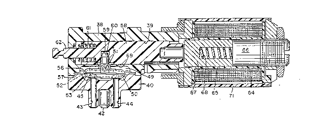
Fig. 1 is a longitudinal, cross-sectional view of a valve
according to the present invention, the solenoid being energized;
and
Fig. 2 is a view similar to Fig. 1 showing the condition of
the valve when the solenoid is deenergized.
The valve chosen to illustrate the present invention includes
a valve body 38 formed with an internal cylindrical bore 39. A
bonnet 40 is secured to the valve body by bolts (not shown) which
pass through holes in the bonnet and are threaded into tapped holes
in the valve body.
Bonnet 40 is ~ormed with a pressurized fluid inlet port 42 and
two outlet ports 43 and 44. The inner end of port 43 is surrounded
by a valve seat 45, and the inner end of outlet port 44 is
surrounded by a valve seat 46.
All three ports open into a valve chamber 49 defined between
valve body 38 and bonnet 40. Accommodated within chamber 49 is

4 2 ~
a rocker valve member 50 pivotally mounted for rocking movement on
an axle 51 extending perpendicular to the longitudinal direction
of cylinder 39. Rocker valve member 50 includes a core 52 of riyid
material encapsulated within a resilient, rubbery material 53.
A diaphragm 56 of limp, flexible, and rubbery material
surrounds valve member 50 and extends radially between the valve
member and the valve body. Diaphragm 56 may be an integral
extension of .encapsulation material 53. The radially outward
margin 57 of diaphragm 56 is s~ueezed tightly between valve body
38 and bonnet 40.
The operator for operating the valve includes a shuttle 58
slidable longitudinally within cylinder 39 formed in valve body 38.
Shuttle 58 is formed with a crosswise bore 59 which accommodates
a rigid stem 60 projecting from core 52 of valve member 50.
Longitudinal movement of the shuttle 5~ within cylinder 39 is
converted into rocking movement of valve member 50 by means of
cooperation between bore 59 and stem 60.
A compression spring 61, within cylinder 39, surrounds a pin
62 projecting from shuttle 58. One end of spring 61 is seated
against an end wall of cylinder 39, and the other end is
accommodated within an annular groove in the shuttle, surrounding
pin 62, and seated aga.inst the bottom of that groove. Spring 61
constantly urges shuttle 58 toward the right, as viewed in the
drawings.
Mounted on the end of valve body 38, opposite the end at which
spring 61 is located, is a cylindrical housing 71 within which is

~; :
~ 8 ~
located a solenoid coil 6~ wound about an axially extending core
tube ~5. ~ixed within the end of tube 65 remote from shuttle 58
is a stationary armature, or plugnut, 66. Slidable within core
tube 65, toward and away from plugnut 66, is a moveable armature
67. A compression spring 68 is accommodated within an axial bore
in moveable armature 67, one end of the spring seating against
plugnut 66, and the other end of the spring seating against the
floor of the bore. Spring 68 is stronger than spring 61, and
preferably twice as strong. In other words, the force with which
lo spring 61 urges shuttle 58 toward the right is substantially one
half the force with which spring 68 urges armature 67 toward the
left.
In use, inlet port 42 is connected to a source of fluid
pressure, and outlet ports 43 and 44 are connected to environments
which are to alternatively receive the pressurized fluid entering
chamber 49 through port 42. When solenoid 64 is energized,
moveable armature 67 i5 attracted to plugnut 66, and moves into
engagement with the plugnut against the force of spring 68, as
shown in Fig. 1. As a result, spring 61 is free to shift shuttle
58 toward the right so as to bring valve member 50 into engagement
with valve seat 46, to close outlet port 44. At the same time,
outlet port 43 is opened. Note that in this condition, shuttle 58
is spaced from armature 67, so that the armature and spring 68 have
no effect on the shuttle.
When solenoid 64 is deenergized, spring 68 is free is move
armature 67 toward the left. The armature immediately engages the

2~3~6~
end of shuttle 5~ and pushes the shuttle, against the force o~
spring 61, toward the left and into the condition shown in Fig. 2,
wherein val~e member 50 engages valve seat 45, so as to close
outlet port 43 and open outlet port 44.
It will be appreciated that in the condition sho~m in Fig. 1,
the only force on valve member 50 serving to cause closure o~
outlet port 44 is provided by spring 61, and in the condition of
Fig. 2, the only force on valve member 50 serving to close outlet
port 43 is the force provided by spring 68. In fact, in this
latter case, the force applied to valve member 50 is actually the
force provided by spring 68 less the opposing force being applied
to shuttle 58 by lighter spring 61. Because spring 68 exerts twice
the force of spring 61, the force applied to valve member 50 in
both of its stable positions, shown in Figs. 1 and 2, i5 the same.
The reason is that in the Fig. 1 position, only the force of spring
61 is applied to the valve member, and in the Fig~2 position, the
force of spring 68 minus the force of spring 61 is applied to the
valve member. Since the force exerted by spring 68 is twice that
of the force exerted by spring 61, the resultant force applied to
valve member 50 in the Fig. 2 position is equal to the force of
spring 61 applied to the valve member in the Fig. 1 position.
It will be seen that, according to the present invention, the
solenoid/armature arrangement 64, 66, 67 is not employed to urge
valve member 50 into either of its stable positions. Instead, the
function oE the solenoid/armature arrangement is to selectively
render sprin~ 68 ineffective with respect to shuttle 58 so that

2~8~
spring 61 can act upon the shuttle and move valve member 50 to one
of its stable positions.
The invention has been shown and described in preferred form
only, and by way of example, and many variations may be made in the
invention which will still be comprised within its spirit. It is
understood, therefore, that the invention is not limited to any
specific form or embodiment except insofar as such limitations are
included in the appended claims.

Dessin représentatif
Une figure unique qui représente un dessin illustrant l'invention.
États administratifs

2024-08-01 : Dans le cadre de la transition vers les Brevets de nouvelle génération (BNG), la base de données sur les brevets canadiens (BDBC) contient désormais un Historique d'événement plus détaillé, qui reproduit le Journal des événements de notre nouvelle solution interne.

Veuillez noter que les événements débutant par « Inactive : » se réfèrent à des événements qui ne sont plus utilisés dans notre nouvelle solution interne.

Pour une meilleure compréhension de l'état de la demande ou brevet qui figure sur cette page, la rubrique Mise en garde , et les descriptions de Brevet , Historique d'événement , Taxes périodiques et Historique des paiements devraient être consultées.

Historique d'événement

Description Date
Inactive : Demande ad hoc documentée 2018-06-06
Exigences relatives à la nomination d'un agent - jugée conforme 2018-05-18
Exigences relatives à la révocation de la nomination d'un agent - jugée conforme 2018-05-18
Inactive : CIB de MCD 2006-03-11
Demande non rétablie avant l'échéance 2000-03-13
Le délai pour l'annulation est expiré 2000-03-13
Réputée abandonnée - omission de répondre à un avis sur les taxes pour le maintien en état 1999-03-12
Demande publiée (accessible au public) 1993-09-19

Historique d'abandonnement

Date d'abandonnement Raison Date de rétablissement
1999-03-12

Taxes périodiques

Le dernier paiement a été reçu le 1998-03-10

Avis : Si le paiement en totalité n'a pas été reçu au plus tard à la date indiquée, une taxe supplémentaire peut être imposée, soit une des taxes suivantes :

  • taxe de rétablissement ;
  • taxe pour paiement en souffrance ; ou
  • taxe additionnelle pour le renversement d'une péremption réputée.

Veuillez vous référer à la page web des taxes sur les brevets de l'OPIC pour voir tous les montants actuels des taxes.

Historique des taxes

Type de taxes Anniversaire Échéance Date payée
TM (demande, 5e anniv.) - générale 05 1998-03-12 1998-03-10
Titulaires au dossier

Les titulaires actuels et antérieures au dossier sont affichés en ordre alphabétique.

Titulaires actuels au dossier
AUTOMATIC SWITCH COMPANY
Titulaires antérieures au dossier
JOSEPH W. BAKER
Les propriétaires antérieurs qui ne figurent pas dans la liste des « Propriétaires au dossier » apparaîtront dans d'autres documents au dossier.
Documents

Pour visionner les fichiers sélectionnés, entrer le code reCAPTCHA :


Pour visualiser une image, cliquer sur un lien dans la colonne description du document. Pour télécharger l'image (les images), cliquer l'une ou plusieurs cases à cocher dans la première colonne et ensuite cliquer sur le bouton "Télécharger sélection en format PDF (archive Zip)" ou le bouton "Télécharger sélection (en un fichier PDF fusionné)".

Liste des documents de brevet publiés et non publiés sur la BDBC .

Si vous avez des difficultés à accéder au contenu, veuillez communiquer avec le Centre de services à la clientèle au 1-866-997-1936, ou envoyer un courriel au Centre de service à la clientèle de l'OPIC.


Description du
Document 
Date
(aaaa-mm-jj) 
Nombre de pages   Taille de l'image (Ko) 
Dessins 1993-09-19 1 62
Revendications 1993-09-19 3 96
Page couverture 1993-09-19 1 14
Abrégé 1993-09-19 1 26
Description 1993-09-19 7 224
Dessin représentatif 1999-06-22 1 30
Courtoisie - Lettre d'abandon (taxe de maintien en état) 1999-04-12 1 187
Rappel - requête d'examen 1999-11-15 1 117
Taxes 1998-03-10 1 44
Taxes 1997-03-03 1 35
Taxes 1996-03-08 1 32
Taxes 1995-03-07 1 32