Note : Les descriptions sont présentées dans la langue officielle dans laquelle elles ont été soumises.
-1- 2~37~
This invention relates to loudspeakers and
loudspeaker systems and is particularly concerned with
transmission line loudspeakers and loudspeaker systems.
Transmission line loudspeaker systems have
traditionally consisted of a woofer or a combination o~
drivers mounted at the end of a long tube. The
simplest form of tube is a pipe of uniform diameter.
At the ~requency where the wavelength of sound is
approximately four times the length of the tube, a
resonance occurs (the "quarter~wave" resonance) such
that the sound which is radiated from the open end of
the tube reinforces that coming directly from the
loudspea]cer drive unit itself. Higher up the frequency
scale the tube will have more resonances, at roughly
odd integer multiples of the quarter-wave resonance
frequency, i.e. 3/4, 5/4, etc. However, these modes
are undesirahle, because it is only the fîrst mode
which provides reinforcement. The higher freguency
modes either reinforce or cancel the direct output from
the loudspeaker drive unit.
Loudspeaker designers usually take two steps
to reduce these higher frequency modes. The first step
is to introduce dampin~/absorption into the system.
The second is to change the shape of the pipe; notably
its longitudinal profile. So far as damping/absorption
is concerned, absorbent material such as foam has a
frequency-dependent attenuation characteristic, so that
higher frequency modes are damped but not completely
eliminated. Placing more absorbent material in the
pipe does not help, because the first mode can then be
damped out so much that the main advantage of using a
transmission line is diminished. So far as changing
the shape of the pipe is concerned, one proposal is to
introduce a taper, so that the diameter of the pipe
decreases in the direction from thP loudspeakex drive
.
: - ~ . . -
.. , ' ' ' .
- : - . . . : . . .
.
~37~
--2--
unit towards the open end of the pipe. However, a
tapered pipe has almost the same acoustic
characteristics at low frequencies as a pipe o~ uniform
diameter, with the result that the resonant modes are
only attenuat0d to a small extent by this technique.
An alternative to the use of
dampiny/absorption materials within the transmission
line is the provision of an acoustic filter or filters
within the transmission line. The inclusion of such
acoustic filter~ makes it possible significantly to
reduce the quantity of mid-frequency and high-frequency
sounds radiated from the end of the transmission line.
These acoustic filters take the form either of an
expanded or a restricted zone of the pipe, or a sexies
of expanded or restricted zones. The expansion zone,
i.e. acoustic compliance, or restriction zone, iOe.
acoustic inertance, in the pipe behave~ like a reactive
low pass filter, similar to a parallel capacitor ~or
series inductor) found in electrical engineering. The
efficacy of such an acoustic filtex is dependent on the
relative sizes of the loudspeaker diaphragm, expansion
or restriction zone or zones, and cross-sectional area
of the pipe. It is important to draw a distinction
between this type of device and some transmission lines
which are known which use a tapered pipe behind the
driver. The acoustic low pass filter works because a
compliance (fox an expansion zone) or inertance (for a
restriction zone) is introduced into the pipe. The
theory for these devices is very different from that of
a tapered pipe which behaves rather like an acoustic
horn, but in reverseO
Fig. 1 of the accompanying drawings shows a
known transmission line loudspeaker system which
comprises the combination of a loudspeaker, a cavity
and a pipe arranged 'in series". Here the cavity is
.
, . . . .
- ,
~, .. . . . . .
.. .
.
7 ~ ~
formed at the end of the pipe and the loudspeaker is
situated immediately opposite the entry to the pipe on
the wall o the cavity most remote from the pipe. In
thi~ arrangement the cavity per~orms the role of an
expansion-type low pass filtAer by being situated
between the loudspeaker and a pipe which has
approximately the same cross-sectional area as the
loudspeaker, although pipes having areas substantially
different from that of the loudspeaker could be used.
The transmission line loudspeaker system of
the present invention, although it uses a low-pass
filter, differs ~rom the system shown in Fig. 1. For
a cavity to have a significant effect on the frequency
response it will necessarily be relatively large.
Therefore, the acoustic pressure distribution within
the cavity will not be uniform across all frequencies.
The relative positions oE the driver, the cavity and
the pipe, and the shape of the cavity, will all have an
effect on the response of the system.
~ It is an object of the present invention to
design a transmissi.on line loudspeaker system having at
least one driver, acoustic filter and transmission
line, in which the response of the system is optimised
or is at least an improvement upon the known systems.
It is a further object of the present
invention to provide a transmission line loudspeaker
system which will produce the desired frequency
response of sound radiated from the open end of the
transmission line.
It is yet a further object of the present
invention to provide a transmission line loudspeaker
system in which the system performance is superior to
commonly available transmission line systems using
constant diameter or tapered transmission line
elements.
. : . . .
- ,
In accordance with the present invention
there i5 provided a transmission line loudspeaker
comprising at least one driver, an acoustic ~ilter and
a transmission line, in which the driver, or one of the
drivers i~ more than one, is positioned at or adjacent
to the entry to the txansmission line such that the
driver ef~ects a parallel drivin~ of both the filter
and the transmission line simultaneously.
Preferably, the acoustic filter comprises a
cavity.
The positioning of the driver, or one o~ the
drivers if more than one, close to the entry to the
transmission line means that the pressures at the
driver and at the entry to the pipe are approximately
equal over a wide range of frequencies.
The pressures at the driver and at the entry
to the transmission line are approximately equal for a
wide range of frequencies, even when modes inside the
c~vity mean that there is a non-uniform pressure
distribution. In this way the con~iguration behaves
more like an idealised acoustic low pass ~ilter.
In a preferred embodiment the driver at or
adjacent to the entry to the transmission line is
positioned on a side wall of the acoustic filter which
is a continuation of a waIl of the transmission line.
Preferably the distance between the entry to
the transmission line and the driver at or adjacent to
said entry is less than approximately one quarter of
the wavelength at the highest frequency at which the
transmission line makes a contribution to the output.
The frequency is pre~erably of the order of
500 Hz.
In a preferred embodiment of the invention
the at least one driver, the filter and the
transmission line are housed within a cabinet, in which
~379~
--5--
a first portion of the cabinet constitutes a cavity
actin~ as a low pass filter and a second portion o~ the
cabinet constitutes the transmission line defined as a
sinuous track ~rom the front to the rear o the
cabinet.
In a preferred embodiment, the driver or
drivers are mounted at the upper front of the cabinet
and the open end of the transmission line is at the
lower rear of the cabinet.
In order that the invention may be more fully
understood, one presently preferred embodiment of
loudspeaker in accordance with the invention will now
be described by way of example and with reference to
the accompanying drawings, in which:
Fig. 2 is a schematic illustration of the
novel configuration o~ driver, acoustic filter and
tran~mission line for a loudspeaker system in
accoxdance with the invention;
Fig. 3 iB an alternative schematic
illustration of the configuration shown in Fig. 2;
Fig. 4 shows a development of the
con~iguxation shown in Fig. 3;
Fig. 5 is a vertical sectional view through a
loudspeaker constructed in accordance with the
invention;
Fig. 6 is a front view of the loudspeaker of
Fig. 5; and,
Fig. 7 is a rear view of the loudspeaker of
Fig. 5.
Fig. 2 illustrates the concept behind the
present invention. The transmis~ion line of the syst~m
is constituted by a pipe 10 of constant cross-section.
At the end of the pipe 10 remote from its open end is
formed a cavity 12 defined by appropriately shaped
walls. This cavity acts as an acoustic filter. In the
,
. .
7 0 !~
illustrated arrangement the cavity 12 ls offset
relative to the central longitudinal axis of the
transmission line, with one wall 14 of the cavit~ being
an extension o~ one wall o the pipe 10. A driver 16
is mounted in the wall 14 adjacent to the entry from
the cavity 12 into the pipe 10. The driver 16 could
alternatively be positioned just within the pipe, or
actually at the junction be~ween cavity and pipe.
Fig. 3 shows the system of Fig. 2 in an
alternative way. Fig. 3 makes it clearer that, in
contrast to the "series" arrangement of acoustic filter
and pipe in Fig. 1, the present invention uses a
parallel arrangement where the driver 16 drives both
the acoustic filter 12 and the transmission line 10 at
the same time. It does this by being positioned at or
close to the entry to the transmission line.
It is an object of the invention to improve
the bass, i.e. low frequency, characteristics of a
loudspeaker, and particularly the response helow
approximately 500 H~. This is the order of frequency
at which the transmission line makes an effective
contribution.
It is this frequency also which is a
determining factor in deciding the maximum distance
that one can place the driver away from the filter/pipe
junction and still achieve an advantage from the
parallel driving. The distance from the centre of the
driver to the junction should not be more than a
quarter wavelength [ /4) at the maximum frequency
appropriate for the transmission lin~ concerned. Thus,
if the frequ~ncy is 500 Hz, using the formula c=f
where c is the velocity of sound, the quarter
wavelength dimension is 1605 cm (6.5 inch), assuming
c=330 metres/second~ If the frequency is taken to be
300 Hz, khen /4 = 27.5 cm (10.8 inch~ etc.
7 ~ ~
The transmission line loudspeaker system
shown in Fig. 2 can be modified by incorporating
additional acoustic filters at strategic points along
the pipe 10, for example in the orm o~ expansion ~ones
or restriction zones. Fig. 4 shows schematically the
additio~ of an acoustic filter 17 in series with the
transmission line 10. The combination of filter 17 and
pipe 10 could be repeated~ in Qeries with the first
~ilter and pipe 17, 10. Also, absorbent filling
material can be incorporated within the pipe 10 and/or
within the cavity 12 to have a dissipative effect.
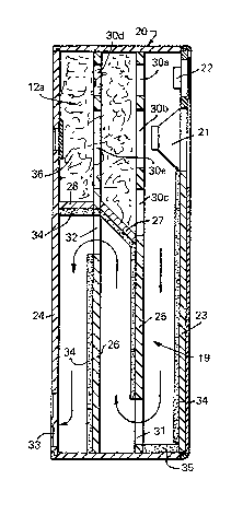
The loudspeaker shown in Figs. 5 to 7
comprises a multi-component housing, indicated
generally at 20. The cabinet includes a front wall 23
and a rear wall 24. A driver 21 is mounted in the
front wall of the housing, at the upper part of the
housing. ~he driver 21 is here within the cavity
(acoustic filter) i.e. spaced from the entry to the
tran mission line, but is sufficiently close to perform
the parallel driving function. A treble unit wlth a
sealed rear enclosure is indicated at 22. Spaced
between the front wall 23 and the rear wall 24 of the
housing are a pair o~ partition walls 25 and 26 which
are parallel to the front and rear walls of the housing
and which divide the interior of the housing into three
approximately equal size parts. Between the partition
wall~ 25 and 26 and approximately halfway up the
partition walls is provided an obliquely extending
dividing wall 27. ~he inclination of the dividin~ wall
27 helps to avoid an abrupt change in the acoustic
propexties. A similar dividing wall 28 is provided
between the partition wall 26 and the rear wall 24 of
the housing, although with the dividing wall 28
extending horizontally. Both the internal partition
walls and the cabinet outer walls are preferably made
.
' . ' . ' . ' ' ' ' ' '
.
.
.. , . ~ .. .. . . . . .
3 ~ ~ ~
of a suitable rigid material such as medium density
~ibreboard or aluminium honeycomb sandwich to give the
structure rigidity.
AbovQ tbe level of the dividin~ walls ~7 and
28 the partition wall~ 25 and 26 are provided with
large-size holes 30a, 30b, 30c, 30d and 30e. Thus, the
volume above the dividing walls 27 and 28 constitutes a
cavity 12a, equivalent to the cavity 12 of Fig. 2. The
cavity is immediately behind the driver 21.
Below the level of the dividing walls 27 and
28 the partition wall 25 is provided with an aperture
31 adjacent to the bottom of the partition wall. The
other partition wall 26 is provided with an aperture 32
immediately below the dividing walls 27 and 28~ The
apertures are all substantially rectangular. The
apertures thus define horizontal struts which provide
bracing and a rigid structure. The cro~s-sectional
area of the apertures 31 and 32 is equal to the cross-
sectional area of the transmission line pipe 19. The
~ rear wall 24 of the housing is provided with a vent 33,
here shown as a double vent, towards the bottom of the
rear wall. The vent 33 shown here has the same area as
the pipe l9, although vents of larger or smaller area
could be used. With this configuration of apertures
and vents 31, 32, 33 there is created within the
loudspeaker cabinet a transmission line 19 which
extends vertically downwards from the driver 21 to the
bottom of the cabinet, upwards from the bottom of the
cabinet to the dividing wall 27, and downwards from
there to the vent 33, thus mapping out a sinuous track
from the driver to the vent. This i5 indicated by the
broken arrows in Fig. 3.
In one embodiment of loudspeaker built as
shown in Fig. 5, the volume of the cavity 12a is
approximately 18 litres and the length of the pipe 19
.
.. .
37~
g
from entry to vent is approximately 1.7 metres (5.5
feet).
Sound-absorbent filling material which has a
dissipative effect is incorporated within the cabinet
to enhance the frequenc~ response. Preerably, the
transmis~ion line section of the system i~ lined with a
fibrous or cellular oam material 34, for example with
a thickness of 15 mm. At the bottom of the cabinet the
lining 35 is preferably of double thickness. The
material of the walls within the cabinet also has a
dissipative effect to a greater or lesser extent.
Alternatively, instead of lining the pipe 19 it can be
filled with a foam or fibreglass material. The cavity
12a at the top of the cabinet is also substantially
filled with the same or similar material 36.
.
'. , . .' .,, , ,. , ~
... , . . , ~ .
: ' ' ' '
. '' . .