Note : Les descriptions sont présentées dans la langue officielle dans laquelle elles ont été soumises.
_1_
ELECTRIC MOTOR VEHICLE CONTROL APPARATUS AND METHOD
FOR REDUCING THE OCCURRENCE OF WHEEL SLIP
Background of the Invention
Field of the Invention
This invention relates to an electric vehicle control
apparatus which is connected to a plurality of motors
provided in an electric vehicle and which controls the
speeds of the motors individually.
Description of the Related Art
An inverter apparatus has been conventionally used
as an electric vehicle control apparatus. Traditionally,
in this conventional method only one inverter apparatus
is used to control a plurality of motors. However,
recently, consideration has been given to the fact that
the diameters of a wheels powering the electric vehicle
are changed by friction which is generated between the
rail and the wheels over time. The changes in diameter
are different for each wheel. Hence it has been
understood that the wheels needed to be controlled
individually. Accordingly, a method has been employed in
which a plurality of inverter devices are connected
respectively to each motor so that they may be
individually controlled. such a conventional individual
control method will now be described in relation to Fig.
z5 i.
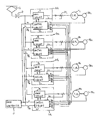
Fig. 1 shows the control structure of an electric
motor vehicle control apparatus using the conventional
individual control method. In Fig. 1, inverter
apparatuses IV1 through IV4 include main circuits Ti
through T4 and control circuits C~1 through C'"
respectively. Electric power from a pantograph 1 is
provided to main circuits T~ through T, through a breaker
2. Induction motors M~ through M, are controlled
-2-
individually in response to the outputs from the main
circuits T~ through Ti.
Control circuits C'1 through C'~ receive a notch
command n (speed increase/decrease) and a direction
command F/R (forward/reverse) from a main controller 3.
Further, the control circuits C', through C°, are provided
with feedback current signals i~ through i, from current
detectors CT, through CT4 and rotor (or wheel) speed
signals s, through s4 from speed detectors TG, through TG,.
The control circuits C' 1 through C', produce gate signals
g, through g, in response to the notch command n,
direction command F/R, current signals i~ through i4 and
speed signals s, through s4. The gate signals are
provided to the main circuits T~ through T, in order to
control the output current.
In the above individual control method, when there
is a difference between the diameters of the wheels
driven by the respective motors, the motors are
separately controlled on each wheel and the torque of the
motors can, therefore, be individually controlled. since
readhesion control can be accomplished when either a slip
or slide (i.e., a deficiency in friction) occurs between
the rail and the wheel, performance of the electric motor
vehicle as a whole is improved. The term readhesion
control refers to control which causes the wheel which is
slipping or sliding to regain sufficient contact with the
rail.
The induction motor can be controlled by reducing the
"slip" (i.e. synchronized speed minus the actual rotor
speed) in the induction motor. Since this "slip"
produces a power loss associated with the induction
motor, as the "slip" is reduced, the efficiency of the
motor is improved.
When a slip or slide occurs between the rail and
wheel, it is important that the condition be detected as
soon as possible so that readhesion control can be
applied. However, in the conventional individual control
_3_ ~09~~93
method, only the speed signal of the wheel on which a
slip is to be detected is used as a source of information
to detect when a slip (or slide) occurs. Utilizing only
a single speed parameter to detect the condition of a
slip (or slide) limits the ability to obtain maximum
control.
Summary of the Invention
It is an object of the present invention to provide
an electric motor vehicle control apparatus in which the
20 precision of detecting the occurrence of a slip (or
slide) between the wheel and rail can be improved and the
reliability of readhesion control can be improved. A
slip or slide occurs when there exists some component of
sliding friction between the wheels and rail. A slip may
occur when the electric vehicle is accelerating and a
slide when the vehicle is decelerating. The features of
the instant invention can be readily applied to both
occurrences with only slight modifications. Hence, the
terms may at times be used interchangeably or singularly
to denote both occurrences.
To achieve the above object according to the
invention, there is provided an eclectic motero vehicle
control apparatus including: (a) a device for generating
a speed signal corresponding to the output of a plurality
of motors; (b) a device for detecting the occurrence of
a slip or a slide one of the plurality of motors by
reference to the speed signals of all of the plurality of
motors; and (c) a device for controlling a control
frequency of the motor detected as experiencing a slip
(or slide).
A further object of the invention is to provide a
method for controlling an electric motor vehicle
including the steps of: (a) detecting a speed of a
plurality of motors driving the wheels of the vehicle;
(b) detecting the occurrence of a slip of a wheel driven
by one of the motors using a speed signal indicating the
_4_ ~~~~~~93
speed of each of the wheels on the vehicle; and (c)
generating a control frequency to control the slipping
wheel in order to eliminate the slip.
brief Oescribtion of the Orawincts
The accompanying drawings, which are incorporated in
and constitute a part of the specification, illustrate
embodiments of the invention, and together with the
general description given above and the detailed
description of the embodiments given below, serve to
explain the principles of the invention.
Fig. 1 is a schematic block diagram illustrating the
structure of a prior art electric motor vehicle control
apparatus;
Fig. 2 is a schematic block diagram illustrating the
structure of one embodiment of the invention;
Fig. 3 is a block diagram illustrating the structure
of a control circuit of the first embodiment of the
invention;
Fig. 4 is a block diagram illustrating the structure
of a control circuit of a second embodiment of the
invention;
Fig. 5 is a block diagram illustrating the structure
of a correction circuit of a third embodiment of the
invention;
Fig. 6 is a block diagram illustrating the structure
of a control circuit of a fourth embodiment of the
invention;
Fig. 7 is a block diagram illustrating the structure
of a control circuit of a fifth embodiment of the
invention;
Fig. 8 is a block diagram illustrating the structure
of a correction circuit of a fifth embodiment of the
invention; and
Fag. 9 is a schematic block diagram illustrating the
structure of a sixth embodiment of the invention.
~5_
Detailed Description of the Preferred Embodiments
Fig. 2 shows the structure of an electric motor
vehicle control apparatus according to an embodiment of
the invention. The elements in Fig. 2 which are the same
as element shown in Fig. 1 are given the same reference
identifiers. Referring to Fig. 2, a control circuit C1,
located in inverter apparatus IV" receives a speed
signal s, from a speed detector TG, coupled to induction
motor M,. Control circuit C~ also receives speed signals
s2 through s4 from speed detectors TGz through TG4.
Similarly, each control circuit, C2 through C,, receive
speed signals s~ through s4 from all of the speed
detectors TG~ through TG,.
Fig. 3 shows the structure of control circuits C,
through Cs according to a first embodiment of the
invention. According to Fig. 3, the control circuit Gt
comprises a slip detection circuit 11, a frequency
control circuit 15, a current reference pattern forming
circuit 19, a gain circuit 20 having a gain constant KB,
an adder 21 and a gate signal generating circuit 22.
Slip detection circuit 11 comprises frequency operation
circuits FD, through FD" minimum value selection circuit
12, subtractor 13 and comparator 14. The frequency
control circuit 15 comprises a switch 16, a gain circuit
17 having a gain constant K" and a subtractor 18. The
gain constant K~ and KH are selected optionally within a
range greater than or equal to than 0 (zero) and less
than 1 (i.e., 0 S K~ and K$ < 1) .
The operation of the slip detection circuit 11 will
be described below in reference to control circuit C,;
however, the remaining control circuits are similarly
constructed.
During normal operation, a notch command n is
provided to the control circuit, e.g., C~, and a current
reference signal i~, corresponding to the notch signal n,
is output from the current reference pattern forming
_6_ '~~~~~~9~
circuit 19. The current reference pattern forming
circuit may include, for example, a table for looking up
the value of current referece signal i' which corresponds
to the input notch signal n. The current reference
signal i' is provided to a positive side of the
subtractor 18 through the switch 16a and may be thought
of as corresponding to a desired speed. A current
detection signal i" from a current detector CT1, is
provided to a negative side of the subtractor 18 which
calculates the difference between the current reference
signal i° and current detection signal i~. The calculated
difference is output to the gain circuit 20. The gain
circuit 20 produces a control frequency signal fsl in
response to the difference from the subtractor 18. The
control frequency signal fs~ is input to the adder 21.
The speed detection signal s~ is provided to the
frequency operation circuit FDA. The frequency operation
circuit FD, produces a rotor frequency signal fr, in
response to the speed detection signal s' from the speed
detector TG1. The frequency operation circuit may, for
example, comprise a voltage to frequency converter. The
produced rotor frequency signal frl is provided to the
adder 21. The adder 21 adds the rotor frequency signal
frl and the control frequency signal fs~ and outputs the
added result as a frequency command signal fl. The
frequency command signal f, is provided to the gate
signal generating circuit 22. The gate signal generating
circuit 22 receives an output voltage reference signal el
and direction signal F/R (F indicating forward and R
indicating reverse) in addition to the frequency command
signal f~. The gate signal generating circuit 22
produces a gate signal gl in response to signals e" F/R
and f,. The gate signal g, is provided to main circuit T~
of the inverter apparatus IV1 for control of the
induction motor M~. The gate signal generating circuit
22 may comprise, for example, a pulse width modulation
control circuit which generates an output g~ in response
'~~9~~9~
to the reference voltage value e, and the desired
frequency f,.
The above operation occurs in the normal operation
mode (i.e., when no slip is occurring). The operation of
the slip detection circuit 11 will now be described. In
addition to the above described operation, the speed
signals sz through s,, from the speed detectors TGz through
TG, are also provided to the slip detection circuit 11.
Frequency operation circuits FDZ through FDA convert the
speed signals s2 through s4 into the rotor frequency
signals fri through fr4 respectively.
The minimum value selection circuit 12 selects the
minimum rotor frequency signal of the rotor frequency
signals fry through fr4. The minimum value is output to
the negative side of the subtractor 13. By choosing the
rotor frequency signal having the minimum value, the
speed associated with a wheel which is least likely to be
currently slipping is chosen.
The rotor frequency signal fr, is provided to the
positive side of the subtractor 13 which calculates a
difference between the minimum signal of the rotor
frequency signals fr2 through frd and the rotor frequency
signal fry. Subtractor 13 provides the difference to the
positive terminal of the comparator 14. A set value a is
provided to the negative terminal of the comparator 14.
When the difference between the value provided by
subtractor 13 and the set value a reaches a fixed level,
the comparator 14 outputs a signal H which indicates that
the wheel is slipping.
As the wheel driven by the motor M~ begins to slip,
the value of the rotor frequency signal fry increases
sharply. However, since the value output from the
minimum value selection circuit 12 does not change
(assuming at least one other wheel is not slipping), the
output from the subtractor 13 increases significantly.
Consequently, the signal H is output to the switch 16 as
a slip detection signal from the comparator 14.
_g_
Upon detection of a slip signal H from comparator 14,
switch 16 switches from side a to side b. Accordingly,
the current reference signal i' output from the current
reference pattern forming circuit 19 passes through the
gain circuit 17. Gain circuit 17 attenuates the current
reference signal i' according to the gain constant x
The attenuated current reference signal i°' is provided to
the positive side subtractor 18 instead of the current
reference signal i'. Consequently, the frequency command
signal f, being the sum of the control frequency signal
fst and rotor frequency signal f,~ is decreased, and
readhesion control is accomplished on the wheel which is
slipping.
In the slip detection circuit 11 according to the
instant invention, in addition to the speed signal s1
from the speed detector TG~ associated with the slipping
wheel, the speed signals s2 through s4 from the other
speed detectors TGZ through TG~ are used to detect when
the slip occurs. As a result it is possible to detect
the slip more reliably and exactly than with conventional
control methods.
Next a second embodiment of the invention will be
explained with reference to Fig. 4. In Fig. 4, a control
circuit C1 comprises a vehicle speed operation circuit
23, slip detection circuit 24, current reference
generation circuit 25, current reference control circuit
26 and frequency output circuit 27.
Frequency operation circuits FD,o through FD,a of the
vehicle speed operation circuit 23 convert speed signals
s,o through s~ into rotor frequency signals fr,o through
fry, respectively, and provide the rotor frequency
signals fro through fry to the minimum value selection
circuit 12. The minimum value selection circuit 12
selects the signal having the minimum value of the rotor
frequency signals fr,o through fry, and provides the
selected signal to a time average circuit 28. The time
average circuit 28 averages the selected signal for a
_g_
sampling period and provides the calculated average to a
differential circuit 29 and a sample-and-hold circuit 30.
The output from the differential circuit 29 is also sent
to a sample-and-hold circuit 31, and then is provided to
an integral circuit 32. The integral circuit 32
integrates the output from the sample-and-hold circuit
31. An adder 33 adds the output from the sample-and-hold
circuit 30 which represents the average minimum speed and
the output from the integral circuit 32 which represents
the average change in minimum speed. The added value is
an estimate of the vehicle speed and is represented by
vehicle speed signal fa. The vehicle speed signal fo is
a signal which has a frequency which represents an
estimated speed of the vehicle.
A subtractor 35 of the slip detection circuit 24
inputs the rotor frequency signal fro from the frequency
operation circuit FDIO and the vehicle speed signal fo
from the adder 33. Subtractor 35 calculates a difference
between signals frlo and fo. The difference is provided
to a dead band circuit 36. The dead band circuit 36
provides a signal to the current reference control
circuit 26 when the difference output from the subtraetor
35 reaches a fixed level. The slip detection signal from
the dead band circuit 36 indicates that a slip is
detected. This signal represents a slip detection since
the rotor frequency signal frio is larger than the vehicle
speed signal fo when a slip occurs at the wheel driven by
the motor M,.
In the current reference control circuit 26, the slip
detection signal is provided to and operated on by a
proportional circuit 37 having a proportional constant Its
and an integral circuit 38. The outputs from the
proportional circuit 37 and integral circuit 38 are added
by the adder 39. The added value from the adder 39 is
provided to a negative side of a subtractor 41 via a gain
circuit 40 having a gain constant KD.
_10~
The current reference generation circuit 25 uses a
current reference pattern forming circuit 42 instead of
the current reference pattern forming circuit 19 shown in
Fig. 3. Current reference pattern forming circuit 42
produces a current reference signal i' in response to
both the notch command n and the vehicle speed signal fo.
The current reference pattern forming circuit 42 may
include, for example, a table for looking up the value of
i' as a function of both the notch comand and the vehicle
speed. The current reference signal i' is corrected by
a correction circuit X~. The corrected current reference
signal i~' is provided from the correction circuit x~ to
a positive side of the subtractor 41 in the current
reference control circuit 26. The current pattern
forming circuits 42 of the control circuits C, through C,
are the same. Accordingly, the current pattern forming
circuit 42 of the control circuit C1 can be used by all
of the control circuits C, through C4, thus eliminating
the need for current pattern forming circuits in control
circuits CZ through C4.
The subtractor 41 in the current reference control
circuit 26 calculates a difference between the output
from the gain circuit 40 and the corrected current
reference signal i~ from the correction circuit XI, and
provides the difference as an attenuated current
reference signal f~' to the frequency output circuit 27.
A subtractor 43 in the frequency output circuit 27
calculates a difference between the attenuated current
reference signal ii' and a current detection signal i"
and provides the difference to a gain circuit 44 having
a gain constant K$. The gain circuit 44 produce the
contral frequency signal fslo in response to the
difference and gain constant KE. The frequency command
signal f, and gate signal g~ are then produced as in the
embodiment of Fig. 3.
According to the above embodiment, the control
frequency signal fs'o is determined by comparing the
~~9~8~3
rotation speed of the wheel fr,o and the vehicle speed
signal fo. In this manner, the generation of slip can be
detected with certainly.
Next the correction circuit X1 will be explained in
detail with reference to Fig. 5.
Since the current reference signal i' from the
current reference pattern forming circuit 42 of the
control circuit C, is used in common by the correction
circuits X, through X4, the correction circuits XZ through
X, are also shown in Fig. 5 with the correction circuit
X~ .
Referring to Fig. 5, the correction circuit X~
comprises multiplier circuits 45 and 46 and a switch 47.
The multiplier circuit 45 multiplies the current
reference signal i' and a correction coefficient FK1, and
the multiplier circuit 46 multiplies the current
reference signal i' and a correction coefficient RK,. The
correction coefficient Fx, is used when the direction of
moving of the vehicle is a forward direction, and the
correction coefficient RK~ is used when the direction of
moving of the vehicle is a reverse direction.
The direction command F/R from the main controller
3 is provided to the switch 47. When the direction
command F is provided to the switch 47, a contact of the
switch 4? is connected to a side F. Further, when the
direction command R is provided to the switch 47, the
contact of the switch 47 is connected to a side R.
Accordingly, the current reference signal i' from the
current reference pattern forming circuit 42 is corrected
in response to the direction of moving of the vehicle,
and the corrected current reference signal i~' is
produced.
The reason why the current reference signal i' is
corrected in response to the direction of moving of the
vehicle will be described below.
Generally, a wheel located at and around the front
of the moving vehicle (front being determined by the
-12_ ~~93893
direction the vehicle is moving) has a decrease of
adhesion activity due to the presence of water, snow,
oil, and the like on the track. Further, the
distribution of axle load changes in response to the
direction of moving of the vehicle as a result of "axle
load movement." Consequently, the maximum rotational
force which may be applied to each wheel without causing
a slip changes with the direction of the moving vehicle.
However, since the correction circuits X, through X4 shown
in Fig. 5 correct the current reference signal i~ in
response to the direction of moving of the vehicle, a
suitable corrected current reference signals i~° through
i~ can be obtained for the motors M, through M4. A value
near the maximum rotational force which can be applied to
each wheel may be chosen and the electric powered vehicle
can be operated while preventing the wheels from
slipping.
Next, a fourth embodiment of the invention will be
explained with reference to Fig. b. In this embodiment,
when the vehicle speed signal fo is calculated, a
difference between the diameters of the wheels is also
considered.
Referring to Fig. 6, a vehicle speed operation
circuit 48 has division circuits DVS through DV4,
respectively located between frequency operation circuits
FD~o through FDA and minimum value selection circuit 12.
The rotor frequency signals fro through fry are divided
by the diameters D, through D~ of the wheels,
respectively. The diameters D, through D~ are
predetermined. The output from the adder 33 is
multiplied by the diameter D, by multiplier 49, and the
vehicle speed signal fo is thus produced. The operation
of other elements and circuits depicted in Fig. 6
corresponding to those in Fig. 4 remains the same and
therefore a detailed explanation is not reproduced.
Next, a fifth embodiment will be explained with
reference to Figs. 7 and 8.
_13_ ~~~~~~3
Referring to Fig. 7, a correction circuit X~o is
provided between the current reference pattern forming
circuit 42 and correction circuit X,. Fig. 8 shows the
details of the correction circuit X,o. An adder 50,
average circuit 51, division circuit 52 and multiply
circuit 53 are provided. The adder 50 totals the
diameters Di through D4 and provides the totaled value to
the average circuit 51. The average circuit 51
calculates the average value D~~ of the diameters D
through D4. In this manner, equal torque may be applied
to each motor using the average value D""~. The division
circuit 52 divides the diameter D1 by the average value
D""~ in order to produce a rate D~/DA"g. The multiply
circuit 53 multiplies the current reference signal i'
from the current referen~:e pattern forming circuit 42 by
the rate D~/D""~, and a new current reference signal i,o is
produced. Accordingly, as the new current reference
signal i~o has a value in response to the diameter D" the
signal i~o is a more suitable current reference signal to
control the motor M,.
Next a sixth embodiment of the invention will be
explained with reference to Fig. 9.
In this embodiment a generalization control circuit
54 is provided and separatable elements of the control
circuits C1 through C, are moved into the generalization
control circuit 54. The generalization control circuit
54 receives the notch command n and direction command F/R
from the main controller 3. Current signals i~ through
i4 from the current detectors CT, through CTS and speed
signals s, through s, from the speed detectors TG~ through
TG4 are also provided to the generalization control
circuit 54. In this embodiment, all common elements in
the individual control apparatus are consolidated into a
generalized circuit thereby eliminating unneeded
duplicate elements. In other words, a single circuit
performs the same function for all of the control
apparatus, thereby reducing size and cost.
'~993~93
In the above embodiments, the situation of wheel slip
during the power running is described. However, this
invention may be used for the case of wheel sliding
during a reduction in speed of the vehicle.
For instance, when a slide occurs, a maximum value
selection circuit, which selects the signal having the
maximum value of the rotor frequency signals fr2 through
fry, is used instead of the minimum value selection
circuit 12 shown in Fig. 3. Further, a subtractor is
used instead of the adder 21 and the control frequency
signal fs, is input to the negative side of the
subtractor.
Further, while the invention shown in Figs. 4-9
illustrate the use of discrete components, the invention
may also be implemented using a microprocessor to perform
the various logical and mathematical functions described.
As described above, according to this invention,
since all of the speed signals of the plurality of motors
are used to detect the slip (or slide) and to perform the
readhesion control, the precision of detecting the slip
and reliability of the readhesion control is improved.