Note : Les descriptions sont présentées dans la langue officielle dans laquelle elles ont été soumises.
g ~ :
Patent
47078
FURNITURE CONSTRUCTION AND METHOD
OF MANUFACTURE
Back~round of the Invention
This invention relates to office furniture and more
particularly to designs for office furni~ure which facilitate
automated on-demand job production of wood office furniture from a
stock of conventional flat wood panels, and to related production
methods.
Various proposals have been made for designs and manners of
assembly of office furniture which facilitate ease of assembly.
This invention relates to improved designs of such furniture and
methods of manufacture whereby a wide variety of furniture designs
and configurations may be produced from standard pref.inished flat
wood panels of ~ubstantial thickness, with a high degree of
automation and ease of assembly into specific furniture units which
may vary one after another in a single-line production process. As
used herein, the terms "flat wood panel" or "flat wood panel
member'l mean a panel or panel member at least ~ inch thick and
formed of solid wood or of wood particles or wood laminates and
whlch is of uniform thickness throughout its length of width. Wood
particle board is a preferred example. Other examples include
solid wood panels and plywood panels.
. . , ,: . . : , : i :-
.
. ~ ' ',
,
8 2
Obiects of the Invention
The general object of this invention is to provide improved
furniture designs which facilitate automated production of office
furniture from flat wood panels.
It is a more specific object to provide such designs which
will provide good structural integrity and strength, pleasing
aesthetic appearance and economy of production.
Another object of this invention is to provide a workstation
top panel structure which is formed of relatively thin flat wood
panel components and which forms a rigid worksurfacP member.
It is a further object of this invention to provide improved
designs of office furniture wherein multiple components are self-
aligning and interlocking, thereby avoiding the need for external
jigging fixtures during assembly.
A further object of this invention is to provide office
furniture constructions whereby desired appearances of various
thicknesses of different components can be obtained readily from
flat wood panels of standard thickness.
Ik is a further object of this invention to provide improved
methods of manufacture of office furniture, including desks.
It is a more particular object of this invention to provide
improved methods of manufacture which readily permit economical
production of a wide variety of completed office furniture, on
demand, in a single continuous production operation from a stock of
flat wood panels.
,::
Summary of the Invention
The furniture is of a design that is adapted for cutting the
parts from standard prefinished flat wood panels and subassembly of
those panel parts into appropriate furniture components, with
subsequent assembly of those components into the furniture unit,
all with internal self-jigging ~self-aligning) and interlocking o~
The parts, thus avoiding the need for any external jigging
flxtures.
The panels may be conventional wood particle board panels,
e.g., high density particle boards, such as 45 lbs or greater, 5/8"
or 3/4" thick, which have a thin finish laminate bonded on one side
and a balancing laminate bonded on the opposite side to seal the
opposite side and to prevent warping. Examples o~ such finish
laminates include paper foils of about O.Q07" thickness and high
pressure laminates of about 0.031" thickness. Such particle board
typically is of varying density through its thickness, being of
relatively high density near each side surface and low density in
the center core zone. For example, this means that fasteners
penetrating through a side surface will be retained much more
firmly than fasteners penetrating through an edge surface.
All of the furniture parts are cut and formad from such wood
panels, preferably by use of automatic tooling such as multi-tool
routers with numerical computer controls (NC). Where the desired
thickness of a component exceeds the thickness of the stock panels
being used, multiple parts are cut and superimposed with one
another to obtain the desired thickness in thP necessary areas,
, ' . ' ~
whether it be only in an edge portion or throughout the area of the
part. Fastener components may be encased at the interface between
such parts. Strength and rigidity of the top structure also is
obtained by the manner of joining such superimposed panel
components, preferably using relatively narrow reinforcement
components on the underside of a single unitary top panel that
provides a finished top worksurface such as for a desk top. Thus
desired strength requirements and good aesthetic appearance are
attained.
The subject designs permit the several necessary parts to be
cut from panels of standard thickness in automated router machining
operations. The fasteners then are applied manually at precisely
machine-defined locations, and the parts are easily and accurately
sub-assembled into the furniture components. The components then
are assembled readily into the complete furniture item, all at
machine-side, without exposed fasteners or external jigging and
with all major exposed surfaces being the prefinished panel
surfaces and the edge surfaces being hidden or separately covered,
providing thereby a finished product which is ready for shipment to
customers directly from machine-side. The flexibility of the
machining process together with the furniture design and assembly
method permit great flexibility from item to item in the same
production operation. This in turn allows rapid production of a
variety of different furniture products "to order" from a single
machine or production line. Neither the components nor the end
products need to be premanufactured for inventory. Rather, a wide
: :: ,~; ~ ~ .. :
variety of products may be rapidly produced "to order", and
therefore may be produced as needed for immediate packing and
loading for shipment, while maintaining the desired strength,
aesthetic and economy goals.
Description of the Drawinas
Fig. 1 is a front view of an office desk employing teachings
of this invention
Fig. 2 is a front perspective view, looking upward from the
right of the desk of Fig. 1 and showing some hidden configurations
in phantom lines, with the glide supports omitted.
Fig. 3 is a rear perspective view, looking upward from the
right of the desk of Fig. 1 and showing some hidden configurations
in phantom lines, with the glide supports omitted.
Fig. 4 is a bottom plan view of the top assembly of the desk
of Fig. 1.
Fig. 5 is an exploded perspective view of the desk of Fig. 1,
omitting the drawer slides and the glide supports as well as many
of the interpanel fasteners.
Fig. 6 is a plan view showing the parts for forming the desk
of Fig. 1, except for the top panel part, as laid out for machining
from a single stock blank wood panel.
Fig. 6A is an enlarged vertical sectional view through a
typical dowel shear interconnection of the top panel and a
reinforcing member in the top structure of the desk of Fig. 1.
.~. - ; ,
,:
Fig. 7 is an enlarged detailed vertical sectional view of the
engagement of a tab of the pedestal hottom panel with the adjacent
end panel assembly of the desk of Fig. 1, as at line 9-9 of Fig. 3.
Fig. 8 is a partial top view of an end panel subassembly of
the desk of Fig. 1.
Fig. 9 is an enlarged fragmentary exploded perspective view of
the top panel, reinforcing members and an end panel at one upper
corner of the desX of Fig. 1.
Fig. lo is a partial perspective view of the inner panel of
the pedestal and related components of the desk of Fig. 1.
Fig. 11 is a partial perspective view illustrating the
engagement of the modesty panel with the left end panel in the desk
of Fig. 1.
Fig. 12 is a partial perspective view of the components at the
pedestal end of the desk of Fig. 1.
Fig. 13 is a partial perspective view of the mounting of a
glide and support therefor in the lower end of an end panel of the
desk of Fig. 1.
Fig. 14 is a vertical section view as at 14-14 of Fig. 12
showing the glide assembly of Fig. 13 fully seated.
Fig. 15 is a perspective view of one known and commercially
available connector assembly such as is presently used in the desk
of Fig. 1.
Fig. 16 is a perspective view of the recesses formed in a
panel for reception and securement of the fixture component of Fig.
~5.
~ ~3 9 ~
Figs. 17 and 18 are top views illustrating the engagement
action between the fitting and the connecting bolt of Fig. 15 as
panel components are assembled and secured together.
Fig. 19 is a top perspective view of another workstation
employing teachings of this invention.
Fig. 20 is another top perspective view of the return
workstation unit of Fig. 21.
Fig. 21 illustrates a drawer front closure arrangement for the
desk of Fig. 1.
Fig. 22 illustrates one alternative drawer front closure
arrangement.
It should be understood that the drawinys are not necessarily
to scale and that an embodiment is sometimes illustrated in part by
schematic and fragmentary views. It should be understood, of
course, that the invention is not necessarily limited to the
particular embodiments illustrated herein.
Descri~tion_of the Preferred Embodiments
The drawings illustrate designs for and production of desks
and similar furniture having major top work surface6. In each
instance, the major top work surface panel is cut and routed to its
~inal configuration from a stock wood panel such as a particle
board panel which has a thin finish laminate on its upper side and
a balancing laminate on its underside. All of the other components
preferably are laid out for cutting and routing to their final
configuration from a single additional stock wood panel of the same
'. ' ' ' ' , `, ' ` ' ,
' :
.
>~
or similar stock wood panels, preferably in a single router
machining operation. An example of such a layout is illustrated in
Fig. 6. A single-pedestal desk 10 formed of these components i5
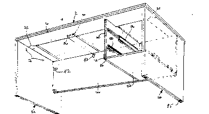
illustrated assembled in Figs. 1 3 and in exploded view in Fig. 5.
The desk 10 includes a top panel structure 12, a pedestal end
support component panel 50, a free end support panel component 54,
a pedestal bottom panel component 58, an inner pedestal wall panel
component 60, and a modesty panel component 66.
Referring also to Figs. 4 and 6, the top panel structure
component 12 includes a top panel 14 and reinforcement and
thickness panel members 16-26. The top panel 14 is prefinished and
provides an unbroken finished top worksurface 15 without any
exposed fasteners. Slx reinforcement and thickness members 16-26
are assembled to the underside of the top panel 14. The members
16, 18, 20 and 22 are formed with outer edges which collectively
are congruent to the outer edge of panel 14 and are in precise
registry with the edges of the top panel. The members 16 26
provide reinforcement for the top, and the members 16-22 also
provide visual thickness ~or the top.
Referring to Figs. 5 and 6A, the top panel 14 and the two
longitudinal members 16 and 18 are ~ormed with shallow bore
recesses 28, 30 in their mating faces. These recesses do not
penetrate through any of these components. The recesses receive
short dowels 31 which are applied with adhesive to join these
components together and provide shear strength at the inkerface for
beam strength and hence rigidity of the assembled top structure 12.
~'' :
:;, :. .: . :
2 ~ 2
The recesses 28, 30 are precisely located in each of these membexs
to assure precise positioning and edge aliynment of the members 16
and 18 with the panel 14 when they are joined by the dowels fitting
in the respective recesses. The end members 20 and 22 and the
pieces 16 and 18 are formed with complementary precisely
interfitting bi-directional "jigsaw puzzle" end configurations 32,
which provide precise bi-directional positioning of these members
within a plane parallel to the top surface, for aligned edge
registry of the members 20 and 22 with the end edges of the top
panel 14.
The central cross pieces 24 and 26 are routed to form partial-
thickness rounded tabs 34 that fit closely within precisely
matching recesses 36 routed into the upper surfaces of the
longitudinal members 16 and 18. The reinforcing member 16 is
formed with an elongated recess 39 in its underside near each end
to receive a tab of each end panel component 50 and 54 as referred
to further below.
The members 16-24 are secured in place against the underside
of panel 14 by adhesive in the dowel joints, as previously noted,
and a few wood screw fasteners are applied through pre-bored holes
40 in the members 16-26 and into the top panel. The dowels and
screws are located at least one inch away from the nearest edge of
the respective components wherever possible, greater separation
being desirable.
The parts also may be adhered at the interfaces if necessary,
but it is preferable to avoid this additional adhesive because of
.~ . ........... . . ............... ~
. ~..
.
~ .
the added steps of application and drying/curing which would be
necessary during assembly.
The underside of the top panel also includes a shallow
elongated recess 41 (see Figs. 4 and 5) for locating and providing
lateral support for the upper edge of the inner panel 60 of the
pedestal, as also referred to further below. The recess 41 is
located to be contiguous to the outward edge of reinforcement
member 26, see Fig. 4.
The top component 12 thus is fabricated of panel materials of
standard thickness while obtaining reinforcement and apparent
thickness of tha top. The dowels or similar inserted interface
elements provide shear strength (force transfer) ~etween the top
panel and the longitudinal reinforcement members to provide good
beam strength and rigidity of the top structure, and to provide
accurate registry of the parts during assembly. No post~assembly
finishing is required, other than applying a covering strip 53 of
wood, plastic or metal over the aligned exposed edge surfaces (see
Figs. 12, 13, 21 and 22).
Referring particularly to Figs. 5 and 6, each of the end
support panels 50 and 54 is formed of two panel parts 50A, 50B, and
54A, 54B respectfully. In each instance, the panel parts are
joined in superposed congruent edge alignment with one another by
inserting and adhesively securing short dowels in recesses 51
formed in the respective faces, in the same manner as described
above with respect to the top structure. Each inner panel 50B, 54B
includes a short integral top tab 52, 55 for engaging the
- : , ...
: ,
: .. j:- :
~ :: ~ : .:: : ,, :
.: . . ~
: .:
2 ~ '~3 ~
respective recess 39 in the reinforcing member 16 of the top
structure. Fig. 8 also shows such a tab 55, as well as
illustrating how one element 42 of an interpanel fastener (referred
to below) is embedded at the interface between the two panel parts
of each end panel by routing a shallow recess 57 in the inner face
of one panel member 50~, 54B at a location to accommodate the top
body of a connector 42 (Figs. 15, 17 and 18) which is mounted on
the facing panel 50A, 54A.
The illustrated assembly utilizes known commercially auailable
fasteners for securing the assembled panel subassemblies to one
another in the desk assembly. These fasteners and their manner of
attachment to the panels and the manner of their joining to one
another are illustrated in Figs. 15 18 of the drawings herein.
Such connectors presantly are provided commercially by Hafele
America, of Archdale, North Carolina. Each of the fasteners
includes a fitting 42 which has a generally cylindrical body
portion 43 at one end and a smaller cylindrical protrusion 44 at
its opposite end. A bifurcated cylindrical cam element 45 is
rotatably mounted in the housing portion 43 and includes an exposed
slotted drive head 46 by which the cam is rotated, such as through
the use of a screwdriver or similar tool. A complementary mounting
bolt 47 includes a screw shank 47A, a stop collar 48, a shank 47B
and a drive head 49 which is slotted for engagement by a driving
tool, such as a screw driver.
The fittings 42 are drive-fit into recesses 43R and 44R
provided at appropriate locations in the respective major panel
11
~ . :
'' '' ' ,: .
.
:, .,
. .
:,
~: , . . ..
,~ . ..
face, near one edge of each panel part to be joined to another
panel; see, e.g., Figs. 5 and 6 which illustrate the recesses, and
a few of the respective fasteners in Fig. 5. Fig. 16 illustrates
the arrangement of the recesses 43R and 44R adjacent one edge of a
panel member, such as the panel 54A. The en~s 42A of the fittings
42 are spaced inward slightly from the respective edge of the panel
in which mounted, see Figs. 17 and 18. Each connecting bolt 47 is
screwed into a hole 47H bored into a major face of another panel
member, such as an end reinforcing member 22. When the panel
subassemblies are joined to one another in the illustrated T-joint
assembly, with an edge of a panel component abutting a side surface
of the respective overlying crossing component, the head and shank
46, 47B of the respective bolt 47 extend into the hollow center of
the cam 45. The rotary cam straddles the neck of the respective
connecting bolt, its cam surfaces engaging the inner end of head 46
with a drawing action as the cam is rotated by an appropriate
turning tool, e.g., a screw driver engaging the exposed screw head
46. The cam gripping, drawing and retaining action establishes and
maintains firm abutting contact between the respective edge surface
of the panel subassembly carrying the ~ixture 42 (such as a panel
subassembly 54) with the side surface of thP overlying panel in
which the bolt 47 is mounted (such as the underside of the top
assembly 12), as further illustrated in Figs. 17 and 18.
Referring again to Fig. 8, a fitting 42 is shown mounted in
the respPctive inner panel 54A. The mating panel 54B is formed
with the shallow recess 57 to accommodate the elongatedi top body
, . .. . . ..
.: ~ . , . , . ~.... . : - .
- ,~
. ~
:: ~ ;
portion of the fitting 42. A hole 56 through the respective inner
panel 50B, 54B communicates with each recess 57 to provide access
to the respective cam drive head 46 of the encased fastener, as by
a screwdriver, for operating purposes.
Referring to Fig. 6, bores 47H are provided in the reinforcing
members 18-~6, panel parts 50B and 54B and panels 58 and 60 where
indicated to receive the mounting bolts 47. The paired sets of
larger circular openings and adjacent small openings along the
panel edges are the openings 43R and 44R for the fastener fittings
42. The larger isolated circular openings are the recesses 26, 28
and 51 for the dowels 31, and the remaining smaller circular bores
(some labelled 40~ are for the wood screw fasteners for use in
securing the panel parts to one another. Suitable bores also are
provided through the inner panel part 50B and in the inner surface
of the inner pedestal panel 60, as at 85 and 87, for locating and
receiving appropriate screws for mounting drawer slides, e.g., the
slides 86 and 88 referred to further belo~-. None of the recesses
or fasteners extend through an externally exposed surface of the
desk or through the surfaces of the end panel 54 or the inner
pedestal panel 60 which are exposed within the kneespace of the
desk 10. In this regard, the access holes 56 are very near the top
of inner panel part 50B, well above the usual line-o~-right of a
user of the desk. Also, the fastener components 42 in the inner
surface of the modesty panel 66 are near the periphery thereof and
at the innermost surface of the kneespace, and hence are not
readily visible.
13
':".
~ .
.
2 V ~
Referring again to Figs. 5 and 6, as well as Fig. 7, each of
the inner end panel members 50B, 54B also is formed with slots 56A,
56B, and 57A, 57B which provide recesses to receive tabs 63 and 64
provided on opposite ends of the modesty panel 66. The inner panel
member 50B also is formed with two slots 68 therethrough, each
being enlarged adjacent the outer surface by a stepped recess 69.
Recesses 70 formed in the inner surface of the outer panel 50A
register with the larger outer portions of the slots 68. As best
seen in Fig. 7, the panel member 50B thereby forms a lip 68A at
each recess, which is engaged by the respective tab 72 at one edge
of the bottom panel 58. Each of the tabs 72 is routed to form a
recess 72A (see Figs 6 and 7~, whereby the tab is L-shaped to be
inserted through the inner portion of the slot 68 and then
downwardly to engage over the respective lip 68A as illustrated in
Fig. 7.
Referring to Figs. 5, 6 and 10, the upper edge of the inner
pedestal panel 60 is of a configuration to form a projecting tab
portion 76 for engaging in the recess 41 in the underside of the
top panel and to con~orm to the undersides of the rein~orcing
members 16 and 18. Tab 76 also abuts the adjacent edg~ surface of
member 26 for further lateral support. The front edge of the
inner-pedestal panel 60 is relieved along its inward edge to form
an outer lip 78. This provides a front edge recess 80 for seating
therein o.f a plastic end cap strip 81 (Fig. 21).
Front drawer end panels 82 and 84 (Figs. 6 and 21) are
provided to be attached to drawers which are to be mounted on pairs
14
- : - , .. : . .~
. ~: . ~ . . - . . .
, ~
. - " . .,. :
.
'; !', ': ~ ,
of drawer slides 86 and 88 mounted in opposed relation to one
another on the inner surfaces of panels 50 and 60, see FigsO 1 and
2. The drawer end panels overlap the cap strip 81, and thus the
end of panel 60, with their opposite edges being adjacent the inner
surface of end panel 50. However, other end configurations may be
used, e.g. as illustrated by drawer end panel 182 in Fig. 22. In
the arrangement of Fig. 21, the strip 81 provides an edge finger
recess 81A for finger-tip access and drawer pull purposes, whereas
in Fig. 22 a corresponding recess 1~3 is formed in the edge of the
front panel.
The modesty panel 66 is provided with a cutout 89 in its top
edge to accommodate passage of wires, such as telaphone, power
cables, etc. It also is routed to provide two sets of fitting
openings 43R, 44R along the inside of its top edge and each end
edge as shown in Fig. 6, to receive fittings 42 as seen in Fig. 1.
Fig. 9 illustrates the interfitting reinforcement members 18
and 22 in relation to the top panel 14 and the interconnection
thereto of the end panel 50. There is shown one of the connector
bolts ~7 in the underside of the member 18 for engagement by one of
the top connectors 42 which are embedded at the interface of the
panel members forming the end panel 50, as described above. In the
illustrated desk assembly, three such top connectors are provided
~or each interpanel connection between these components; see also
Figs. 4 and 5.
Fig. 10 illustrates the assembly interconnection of the inner
pedestal panel 60 to the top assembly 12, modesty panel 66 and
,. ~
- ~ -
,: , ;
- . ` ' ~ .. ; , ' ' :
pedestal bottom panel 58. The modesty panel is provided with an
elongated shallow recess 90 which receives an edge protrusion 92 of
the inner panel 60, sea also Figs. 5 and 6. Fasteners 42 mounted
on the inside of the panel 60 engage complementary fastener bolts
47 in the underside of the reinforcing member 16 of the top
structure 12 and in the inner surface of t]he modesty panel. Two
fasteners 42 in the adjacent end of the bottom panel 58 engage
complementary fastener bolts 47 in the lower edge of panel 60. The
engagement of the tab 76 in the recess 41 in the underside of the
top structure also is illustrated in Fig. 10.
Figs. 11 and 12 illustrate the engagement of the end tabs 63,
64 of the modesty panel 66 and the end tabs 72 of the bottom panel
58 into the recesses formed in the end panels 50 and 54. Two
fasteners 42 in each end of the panel 66 and one fastener 42 in the
end of bottom panel 58 engage respective ~astener bolts 47
appropriately located in the end panels 50 and 54. As indicated by
the recesses at the inner end of panel 58 in Fig. ~, a single
fastener 42 similarly mounted at the lower center inner portion of
the bottom panel 58 engages a fastener bolt 47 appropriately
located in the abutting surface of the modesty panel 66 (see also
Figs. 5 and 12).
Figs. 12, 13 and 14 illustrate the mounting of glides in the
lower edges of the end panels 50 and 54. Parallel grooves 93 and
94 are milled into the lower end edges of the. respective panel
members 50A, 50B and 54A, 54B, and each panel member i5 formed with
a shallow surface recess which complement one another to form an
.
aperture 95 in the subassembly comprising the respective end panel
50, 54. A short U-shap~d metal channel member 96 is inserted with
its flanges engaging the respective grooves 93, 94, straddle of the
interpanel joint, as illustrated. The channel 96 threadably
engages an adjustable glide 97, the stem of which is freely
received within the recess 95, and also reinforces the panel
subassembly.
Assembly of the desk 10 from the subassemblies 12, 50, 54, 5~,
60 and 66 is affected by positioning and ma1:ing the end panels and
modesty panel on the top structure, and securing the fittings 42 on
the respective prepositioned connecting bolts 47. The pedestal
bottom panel is similarly positioned and afixed, fo:Llowed by
positioning and securement of the inner pedestal panel. Cover
strips 53 of wood, plastic or metal are applied over the exposed
panel edges, e.g., the vertical edges of end panel components 50
and 54 as well as the edges of the top panels, as noted above in
referring to the top panel structure 12.
Figs. 19 and 20 illustrate another workstation 108 which
emhodies the same construction and assembly principles. The unit
108 includes a single pedestal desk 10 as described above and a J-
return 110. Components of the return which correspond to those of
the desk 1~ are identified by corresponding numbers in the one-
hundred series. The top structure 112 is of a generally J-shaped
configuration, defining a U-shaped recess 111 for a keyboard
station at the inner corner of the J. ~ keyboard support lllK is
shown in this space in Fig. 19, being supported by an articulating
:
::: ,
- ; :
support mechanism of a known type which is mounted on the underside
of the top structure in a known manner.
The top panel 114 has the J configuration. The rPinforcing
members are shown in phantom lines and are best seen in Fig. 20.
They include a rear member 118, two front members 116A, 116B and
two end members 120 and 122 which also have multi arcuate "jigsaw
puzzle" bi-directional locating joints 32 with the front and rear
members. A third front reinforcing member 116C is of a generally
C-shape to extend around the inner portion of the recess 111. The
member 116C has an inner edge conforming to the inn~r portion of
the recess 111, one end portion 116M having a mating configuration
32 with the respective end of reinforcing member 116B, and an
opposite end portion 116N which spans between members 116A and 118
as illustrated. End portion 116N abuts the inner edge of member
116A and also fits in a notch 119 in member 118. The reinforcing
members are joined to the top panel 114 with dowels and screws to
provide edge thickness as well as reinforcement in the same manner
as described above for the top structure 12. A further rectangular
pad 123 is affixed to the underside of the top panel 114 along the
extended centerline of the recess 111, and has a tongue-and-recess
interfit with the outer edge portion of member 116C as shown. The
pad 123 provides a mounting location for the keyboard support
mechanism.
The end panel 154 and front panel 154A each is ~ormed of two
matching panel parts jolned to one another in the same manner as
panel 54. The panels 154 and 154A are provided with tabs which
.
8 ~
engage recesses in top panel component 112 as in the desk 10. The
modesty skirt 166 is joined to the end panel component 154 and to
top panel component 112 in the same manner as the modesty panel 66
in desk 10. A free end 167 extends beyond top 112 to overlap the
inner surfac.e of the end panel component 50 of the desk lO. The
top structure 112, panels 154-15~A and modesty panel 166 are
assembled to one another and joined by fasteners 42 in the same
manner as the components of desk 10, including the embedded
fasteners in the double-thickness panels 154 and 154A.
The return 112 is joined to the single pedestal desk 10 by
positioning the two units together with the top panels in aligned
abutting coplanar relation as in Fig. 19 and the extended end 167
of the modesty panel 166 adjacent the inner surface of the end
panel component 50. Screws are applied through the holes 171 in
panel 166 and into panel 50. A metal plate 175 also spans the
underside of the joint between the two top panel components 12 and
112 and is secured to both by screws.
In the preferred method of this invention separate layouts are
created for producing all of the panel parts for one complete
assembly of a unit of office furniture from as few stock wood
panels as possible. Such panels typically are 49" to 61" wide and
8' to 16' long. For example, the desk 10 is laid out for cutting
the top panel from one blank and all other panel parts are laid out
for cutting from one further blank as illustrated in Fig. 6. The
layout includes the precise locations for all subassembly
components and fasteners, including the tabs and recesses and bores
19
- - . ::
,
and recesses for all fasteners for accurate positional interfitting
relationship of all of the parts. Appropriate instructions for
precise automated cutting and routing of all shapes, holes and
recesses of the various parts are recorded for readout in the
controls of an automatic, multi-tool NC controlled router.
Typically, all parts are cut from one or two panels in a
corresponding number of machining set-up operations, that is, one
set-up per panel.
The assembly dowels, fasteners and drawer slides, where
appropriate, then are manually inserted and secured in the panel
parts, adjacent the machine site. The components to be formed of
multiple panel parts are sub-assembled in the same manner and at
the same location. In producing the desk 10, these subassembly
operations include the assembly of the top structure ~2, the end
panels 50 and 54, and the inner pedestal panel 60, and applying the
fastener components to all components in the machine formed hores
and recesses which precisely define the locations for all
components except the edge trim.
The resultiny desk components then are assembled and joined to
one another by assembling the two end panels and the modesty panPl
onto the top panel, by aligning and securing the respective
fasteners 42, 47. This is followed by adding the pedestal bottom
and inner panels and securing the respective fasteners 42, 47.
None of the fasteners are exposed at an external surface of the
assembled desk. Appropriate trim strips are applied over the
,
;
8 ~
exposed edges, as desired, as by using flexible bands of plastic or
wood molding.
Similarly, the matching drawer front panels 82 and 84 are
applied to stock preassembled drawer structures, and the resulting
drawers are inserted into the pedestal on the drawer slides.
It will be noted that each of the prospective inter-panel
joints between the end support panels and the top structure,
between the modesty panel and the end panels, between the pedestal
bottom panel and the adjacent end panel and between the inner
pedestal panel and both the modesty panel and the top structure
includes integral tab portions of one of the panels to be mated
into a corresponding recess of the other panel across each
interpanel plane. That is, each panel has at least one tab-and-
recess interconnection with a ~oining panel. These tab-and-recess
interconnections are provided in the areas where high loads or
impact forces are most likely to be applied to an edge abutting
panel in a direction transverse to the joint, generally parallel to
the plane of the cross-joint panel. All of the panels are secured
in firm abutting relationships with one another by the cam~type
quick attachment fasteners.
A J-return 110 or any other furniture unit of a structure
similar to desk 10 or return 110 is produced in the same manner by
a corresponding sequence of operations.
The result i~ a completed office furniture unit, ready for
shipment directly to the customer. The entire manufacturing
operation may be completed within as little as 30 minutes time,
21
,~
2 ~ 8 ~
with no inventory other than the stQck panels, fasteners, basic
drawers and trim strips. Moreover, due to the flexibility of
computer controlled machining together with the furniture designs
and methods provided, successive pxoducts produced by the same
machine and operating personnel can be of distinctly different
configurations and/or models. Thereby, ord~ers for a wide variety
of office furniture may be filled promptly on demand, without an
inventory either of assembled furniture or of precut components.
When a multi-unit such as the desk ancl return of Fig. 19 is
involved, the two units are subsequently joined to one another at
the use site.
It will be seen that the aforementioned objects have been met.
Various modifications of the illustrated preferred embodiments
may be made without departing from the spirit and scope of this
invention. For example, various flat wood panels may be used and
the furniture units may be of a wide variety of designs and
functional purposes. Other quick fasteners may be used, though a
design which assures snug abutting relation of the joined
components, as by a cam action, is preferred.
While particular embodiments of this invention are shown and
described herein, it will be understood, of course, that the
invention is not to be limited thereto since many modifications may
be made by those skill~d in the art, particularly in light of the
foregoing teachings. It is contemplated, therefore, by the
appended claims, to cover any such modifications as fall within tha
true spirit and scope of this invention.
.
-: