Note : Les descriptions sont présentées dans la langue officielle dans laquelle elles ont été soumises.
2as~2~
AUTOMATIC PRESSURIZED RESERVOIR BLEED VALVE
The present invention relates to bleed valves
in ~Lessurized hydraulic and ~e~ -tic systems.
Most particularly, it relates to a bleed valve for
- removing air from a ~res~u-ized hydraulic fluid res-
ervoir.
Bleed valves of various types have been p1aced
in reservoirs and fluid Le~uL~ lines of hydraulic
6ystems. These valves serve to differentiate be-
tween fluid in ~Aceoll~ form and fluid in liquid form
and vent, or bleed, either the gaseous or liquid
form. Many of these valves have been large and of-
ten have been -- Ally v~e~ed. Compact, automatic
bleed valves for such systems have been described in
U. S. Patents 4,524,793 and 4,813,446 to Silver-
water, and co~en~n~ U. S. Patent Application
07/887,836, all a~signed to the assignee of the
present application.
A ~eneL~l theory of o~e~Lion of these automat-
ic bleed valves is ~Yrl ~ i n9~ in U. S. Patent
4,524,793. A capillary and an oriflce are placed in
series in a fluld ~h~nn91 to cau~e the pressure dis-
tribution along the ohAnn~l be~ a high ~les~ule
-~ 25 point at the reservoir end of the valve and a low
~ es~u~a point at the ~iSch~rge end of the valve to
vary Aep~n~ i ng upon the phase of the fluids flowing
in the chAnn~l. This theory is based upon the known
fact that, in such an arrAnq~ ~ ~, a steeper pres-
sure gradient will occur over ths orifice in the
case of gaseous phase flow and, conversely, a steep-
er gradient will be observed over the capillary por-
tion of such a chAnn~l during liquid phase flow. The
variation in the pressure distribution in the chan-
nel may be utilized to con~-ol the opening and clos-
40879
. ~
,
'
.
7 ~
ing of a differentiating valve, depending upon thephase of flow th~o~h the valve. The preferred em-
bodiment disclosed in U. S. Patent 4,524,793 is au-
tomatic and, thus, mitigates the need for constant
operator vigilance.
Thus, each of the afol~ -ntioned bIeed valves
utilizes a series connection of a capillary and an
orifice and ~G~ on the fact that a different
pressure drop across the capillary occurs when the
fluid is flowing in a gas as opposed to a liquid
phase. The pressure drop across the capillary is
related to the viscosity of the fluid flowing
through the capillary and both the spring tension
and the capillary size must be adjusted to the par-
ticular fluid viscosity.
Many liquids used in-hy~Laulic applications
(such as oil) have a vi~cosity that varies greatly
with t~ aLuLe. ~ea~llce the design of these con-
ventional bleed valves must be directed to a partic-
ular visco~ity, they may not work as reliably inenvironments in which wide t~ ~- a~u-e variations
result in ~h~n~e~ in the viscosity of the fluid
flowing through the bleed valve. Consequently, this
problem is particularly acute when the device is
utilized in an envi- - ~ with very wide tempera-
ture swings, such as in aerospace applications.
Cor.ven~ional bleed valves are also difficult to
miniaturize and manufacture because of the lenqth
and diameter of the capillary.
- 30 Accordingly, the present invention provides an
automatic bleed valve for a pressurized fluid reser-
voir comprising:
a housing including an inlet pA~s~ge and
an outlet passage and defining a piston ch: ' ~r hav-
ing an upstream end connected to the inlet passage
- 2 -
40879
2~27~
and a dot...~ ~L eam end connected to the outlet
p~cs~g~;
a piston located within the piston ~hr '-
~and dividing the rh: '-r into an ~ eam fiuid
space ~ icating with the inlet passage and a
dC ~ LL eam fluid space communicating with the outlet
passage, the piston having a fluid p~s~ge providing
fluid communication ~6t - the u~Leam fluid space
and the ~.c.n.D~e~m fluid ~pace and including a first
orifice ~spose~ in the fluid ~cs~ge;
means for urging the piston in an u~DL~
direction; and
a ~econ~ orifice portion located in the
outlet pA~sAge.
The present invention also provides an auto~at-
ic bleed valve for a ~Les~uLized fluid reservoir
comprising:
a fluid ~h~nnel including a first re-
~tricting orifice and a cec~A restricting orifice
and defining fluid communication from the reservoir
th,~u~l, the first restricting orifice and the second
restricting orifice in series; and
a conLLoller coupled to the fluid flow
channel to detect r-hr ,9F in a differential pLes~u,e
due to ~hAng~ in a fluid phase across at least one
of the first restricting orifice and the secon~ re-
stricting orifice and to seal ofP the fluid flow
through the fluid ch~nnel in response to the differ-
ential pressure rear-hin~ a predeteL ined level.
The present invention further provides an auto-
~: matic bleed valve for a pressurized fluid reservoir
comprising:
a fluid ~h~nnel including an outlet, a
first restricting orifice, and a second restrlcting
orifice, and defining fluid c~ I;cation in series
- 3 -
40879
.. ~ . . .
~' . '' ,: .
. .~
2~95274
from the reservoir through the first restricting
orifice and the second restricting orifice to the
outlet, wherein the outlet is at a lower pressure
than the reservoir, wherein the pressure bet _cn the
first restricting orifice and the second restricting
- orifice is P2, and wherein the ratio of a diameter of
the first restricting orifice to a diameter of the
second restricting orifice is substantially the ra-
tio that achieves the maximum difference in value of
P~ betleen a fluid in a gaseous phase and the fluid
in a liquid phase;
a col.L~oller coupled to the fluid flo~
rh~nnel to detect chAnges in a differential ~Les~uLe
across at least one of the first restricting orifice
and the second restricting orifice and to seal off
the fluid flow thLou~l. the fluid channel in refip~nce
to the differential ~res~ure re~h~ng a predeter-
mined level.
r ~ s of the present invention thus use
an entirely different ~ from cor.vel,~ional
automatic bleed valves which used a series connec-
tion o~ a capillary and an orifice. The present
invention is predicated on the discuv~y that two
orifices in series are superior to a capillary and
orifice in series. In : ~o~ s of the present
invention, a differentiating piston with a passage
including a first orifice is utilized as a control-
ler in series with a secQn~ orifice to accomplish
the bleeding pL ocess. An auto~atic bleed valve em-
bodying the present invention thus has the advantagethat the pressure drop across the first orifice is
independent of the viscosity of the fluid and,
therefore, indep~n~t of t~ ,- ature. There~ore,
unlike the co~lvelll ional automatic bleed valves, em-
ho~i -nts of the present invention are indep~n~nt
40879
~ ' ' .
2~9~2-74
of fluid viscosity and temperature.
r ~ s of the present invention have nu-
~ us additional advantages over conventional auto-
matic bleed valves. For example, automatic bleed
S valves embodying the ~esen~ invention are more eas-
ily manufacturable and more capable of ~eing minia-
turized. They have a minimum of seals and moving -;~
parts, thus reducing the possibility of - ~:An1cal
failure and minimizing problem8 which may be cA-~ce~
by dirt or highly v~scol~ contaminants present in
the syste~.
Figure 1 is a sectional view of an automatic
bleed valve embodying the ~esenL invention;
: Figure 2 is a sectional view of the lower valve
housing of the bleed valve of Figure 1;
Figure 3 is a sectional view of the upper valve
h~llc~ ng of the bleed valve of Figure 1;
:~ Figure 4A is a top view of the piston of the
pleed valve of Figure l;
Figure 4B is a sectional view along line 4B-4B
of the piston of Figure 4A.
Figure 5A is a top view of the poppet of Figure
l;
- Figure 5B is a sectional view along line 5B-5B
of the ~op~eL of Figure 5A;
Figure 6A is a top view of the orifice of Fig-
ure 1;
Figure 6B is a sectional view along line 6B-6B
of the ~opp~ of Figure 6B;
Figure 7A is a top view of the spring of Figure
l;
Figure 7B is a sectional view along line 7B-7B
~ o~ the spring of Figure 7A.
:~
- 5 -
40879
~ , .
. -
.. ~ , ~ :
: ~ .
2~9~27~
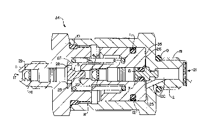
An exemplary automatic bleed valve 34 : ~.lying
the present invention generally comprises a housing
and a piston slidably positioned in the housing.
The housing may be configured in a variety of ways.
For example, in the ~ t illustrated in Figure
. 1, the housing comprises two pieces, a first housing
piece 2 and a seconA housing piece 1. The first
housing pieae 2 has an inlet 21, inlet housing
threads 19, and a boss seal 9, as shown in Figures 1
and 2. A filter 7 is preferably disposed in the
inlet 21.
A piston ch: ~~ 25 is formed by inner walls of
the first housing piece 2, and an inlet p~s~ge 20
provides fluid ~ ;cation Lel._- the inlet 21
and the piston chr ~_ 25. An O-ring carrier 3 is
; preferably mounted to the first housing piece 2 and
extends into the piston cha~ber 25. An O-ring 13 is
mounted on the 0-ring carrier 3.
. The second housing piece 1 has an outlet 17 and
an outlet p~cs~ge 29, as shown in Figures 1 and 3.
The second housing piece 1 may be removably or per-
manently attached to the first housing piece 2 in
any suitable -nner including, for example, by mat-
ing threads 18. A valve housing O-ring seal 10 may
be disposed bet7--~~.the first and second housing
pieces 1, 2 to ~levenL the leakage of fluid from the
piston ~h; ~_~ 25.
The piston 4 is slidably engaged with the inner
~ walls of the housing in the piston chr '-~r 25 and
divides the piston chamber into an u~LL~- fluid
space 26 and a do~..,s~Leam fluid space 27. The outer
wall of the piston is preferably sealed to the inner
. wall of the housing in any suitable -nner to pre-
vent fluid from bypassing the piston. For example,
a piston O-ring 12 and a glyd-ring or cap strip 11
- 6 -
~ 40879
.~
; 2~9~274
formed, for example, from Teflon may be provided in
a groove in the piston outer wall.
In the exemplary ~ L, the piston ch: ~er
25 and the piston 4 are cylindrical but could be
made in any co.,venient cross-sectional shape, for
- example, octago~Al. The piston 4 may have, for ex-
ample, a 0.75 inch diameter. The piston further
include6 a ~luid p~c5Ag~ com~unicating b~t.~e~n the
~ Leam and dc~ Lleam fluid ~F~ae~ 26, 27. The
fluid pAcs~ge may be variously configured and in the
exemplary ~ L comprises a piston pA~s~ge 24
axially aligned with the piston 4. The piston.pas-
sage 24 near the u~-Lleam end of the piston is large
~r.ougl. to accept the 0-ring carrier 3 and the 0-ring
13. While the tolerances b~t. 3- the 0-ring carrier
3 and the piston wall defining the piston pA~sage 24
are large ~o~gl~ to allow fluid to flow bet
them, the 0-ring 13 in the o-ring carrier 3 i~
squeezed between the piston 4 and the 0-ring carrier
3 such that fluid flow through the piston pAC6Age 24
of the piston 4 is blockqd. A ,ecess in an 4~D L eam
end 35 of the piston 4 communicates with the inlet
21 via the inlet pA~s~gQ 20.
A ~ eL 5, shown in Figures 1, 5A, and 5B, is
fixedly disposed in the ~ .."s~Leam fluid space 27
and preferably includes an end portion 22 axially
aligned with and disposed within the piston passage
24 through the piston 4. There is a loose tolerance
beL.~een the end portion 22 of the ~ eL 5 and the
inner wall of the piston so as not to i ~ fluid
flow from the piston pA~sAge 24 to the d~A--~L~eam
fluid space 27. The poppet 5 also includes a flange
36 having outlet op~ning& 28 to allow fluid to pass
from the do~.~,sL ~-- fluid space 27 to the ou~et -
passage 29. Between the ~o~pe- end portion 22 and
- 7
40879
,
-
-: . :. '
. . -;- :
: ~
~ .
209527~
the flange is a seat 23 which is preferably conical-
ly ~h~reA and is sized to seal the downstream end of
the piston passage 24. As the piston 4 slides to-
wards the outlet 17, the piston 4 seats on the seat
23 of the popy~L 5 so that no fluid will pass from
the piston pACsAge 24 into the downstream fluid
space 27.
The automatic bleed valve further includes a
means for urging the piston toward the u~LLeam end
of the housing. This means is preferably a spring 8
and may be located in a varîety of positions within
the housing. For example, in the illu~L ~Le~ qmbod-
iment, the spring 8 is ~;fpose~ in the do~.,s~eam
fluid space 27 between the ~econ~ housing piece 1
and the piston 4. The spring 8 is preferably a he-
lical c_ ~ ession spring. A spring constant of the
spring 8 may be selected based on such factors as
the reservoir ~ es~uLe and the piston configuration.
In a preferred embo~i L, the spring force is set
80 that it requires approximately 12 ~Gu--ds of force
to move the piston 4 ~A1n~t the spring bias such
that the piston 4 ~e~ -6 seated ag~in~t the seat 23
of the ~ eL 5. This is a significant advantage
over conventional bleed valves which are designed to
operate at a spring force of only about 1 pound of
force.
In accordance with an i ,a~Lant aspect of the
a~a~d~us, the fluid channel through the automatic
bleed valve 34 includes two orifices 6, 16 in se-
ries. The first orifice 6 is preferably located inthe piston 4 and the ~econ~ orifice 16 is preferably
located du~ L~eam from the piston 4. For example,
in the illustrated ; ~ L, the first orifice 6
is located in the piston passage 24 and the second
orifice 16 is located in the outlet passage 29, as
: ' .
- 8 -
40879
,~
.
209~274
.
shown in Figure 1. Each orifice 6, 16 may be con-
figured in a variety of suitable ways. In a pre-
ferred ~ , each orifice 6, 16 comprises a
Lee ~et available from Lee C- ,-ny in Westbrook,
Connecticut. As shown in Figures 6A and 6B, each
- orifice 6, 16 includes a generally cylindrical, hol-
low casing having a restricted op~ni ng 33 which de-
fines the orifice ~dt lE~~ first and second filter~
31, 32. In the illustrated embodiment, the re-
stricted opon~n~ in both orifices 6, 16 have the
same diameter. ~or example, each op~ni n~ may be
about 0.004 inch in order to limit the flow of oil
to about 1500 cc per hour in the event of failure of
the 0-ring seals. Alternatively, the restricted~
15 openir3 of the orifices 6, 16 may be larger or -~
smaller than 0.004 inch and may have different diam-
eters. The orifices, 6, 16 are preferably press fit
within the piston pAeff~gQ 24 and the outlet pA~sAge
29, ~e4~e~Lively. An interfeL~n~e fit b~oe~ the
piston 4 and the first orifice 6 and between the
secon~ housing piece 1 and the seco~ orifice 16
seals the ori~ices 6, 16 within the fluid nhAnn~l
and ~r_~..Ls bypass of fluid around the orl~iaes 6,
16.
In a preferred mode of operation, the automatic
; reservoir bleed valve 34 may be threaded to the res-
ervoir (not shown) at the inlet 21 using inlet hous-
ing threads 19. The boss seal 9 then seals the au-
tomatic bleed valve 34 to the reservoir. The auto-
matic bleed valve 34 is preferably coupled to the
highest point in the reservoir where the g~eeo~le
phase of the fluid contA;ne~ in the reservoir is
likely to collect. Before the reservoir is ~Les~uL-
- ized, the spring 8 forces the upstream end 3~ of ~he
piston 4 against the first housing piece 2. In this
,
_ 9 _
' 40879
i
, 1 '
... :
~ .
- . ,
2~9~27~
position, the 0-ring 13 is located within and seals
the piston p~Cs~ge 24. Thus, this arrangement of
the 0-ring 13 and the 0-ring carrier 3 serves as a
check valve, p e~en~ing fluid flow from the ambient
environment into the reservoir. Alternatively, this
- check valve function may be implemented in other
suitable ways.
When the system, e.g., the hydLaulic system, is
activated, the pressure in the re6ervoir builds up.
As the ~Less~Le in~Leas0s, gas flow6 out of the
pressurized reservoir, into the inlet 21, through
the filter 7, and into the inlet p~CsAge 20 anq the
u~Leam fluid space 26 of the piston ~h ~ 25.
The fluid is ~lG~en~ed from entering the piston pas-
sage 24 by the 0-ring 13 in the piston pAssAge 24.
As the ~Les~u,e f~,Lhel increases, a sufficient
force is exerted on the piston 4 to move the piston
4 AgAin~t the force of the spring 8 toward the down-
stream fluid space 27. At a ~lede~ermined threshold
~ es~u~e, the piston 4 moves far ~ough that the o-
ring 13 clears the piston 4 and fluid flow through
the piston pACsAqs 24 is established. For an outlet
at atT~ ic ~La~uLe~ the piston 4 and spring 8
may be configured such that the 0-ring 13 clears the
piston 4 once the pressure in the reservoir is ~e-
tween about 25 and about 45 psi.
From the u~ eam fluid space 26, the fluid
flow path extends through the piston passage 24,
through the first orifice 6, and into the downstream
fluid space 27. From the ~ Leam fluid space 27,
the fluid flows thLoù~ll the outlet openings 28,
through second orifice 16 in the outlet passage 29,
and out of the outlet 17.
, .
- 10 -
40879
20s~27a
As the fluid enters the downstream fluid space
27, a back pressure is created which tends to force
the piston 4 back towards the ~L~am side. The
tension of the spring 8 is set such that, when the
fluid is in the ~ceo~lC phase, the piston stays in
- an equilibrium region in which the o-ring 13 clears
the piston 4 but the piston 4 is not seated on the
6eat 23 of the pGp~e~ 5, allowing the gas to flow
~hLvu~l- the fluid çhAnnel to the outlet 17. This
equilibrium position may be determined in accordance
with an eguilibrium equation which can be expressed
as:
P~ * A1 = (P~ * A2) + Spring Force
where
P1 = PL-'S~ULe in the U~D~ fluid space
P2 = PL-~6~UUe in the ~ .. - -L~. fluid space
Al = Upstream Piston Area
A2 = De.. ~Leam Piston Area
Although the theory of operation ~ay not be
completely u-.dal~Lood, it appears that when two ori-
fices of equal size are placed in series and a ga~
is passed through them, the ~Les~ure drop across the
first orifice 6 may be less than the pressure drop
across the second orifice 16. For example, 20% of
~; the inlet pressure may drop across the first orifice
~- 6 and 80% of the pressure may drop across the second
orifi~e 16 when the fluid is in the gaseous phase.
However, when a liquid is p~se~ through the two
orifices 6, 16 in series, the pressure drops may be
approximately equal. This ph~nl n~n can be uti-
lized to allow for the automatic operation o~ a ~
bleed valve according to the present invention.
-- 11 --
40879
.'
-
2095274
As an example of one .- 'o~ t, it is useful
to ~ ;ne the situation where the above mentioned
equilibrium is est~hl i ~h~d when the fluid flowing
through the piston p~sAge 24 is in the gasêous
phase. So long as a gaseous fluid is flowing
through the fluid ch~nnel~ the piston 4 will stay in
the equilibrium region. However, once all of the
gas has been bled from the reservoir and fluid in
the liquid phase enters the piston passage 24 and
passes through the first orifice 6, the pressure
drop across the first orifice 6 will in~,ease. This
i..~Lease in ~Les~u~e drop across the first orifice 6
c~llses the piston 4 to move ~g~in~t the force of the
spring 8 onto the seat Z3 of the ~o~L 5, seAling
the fluid chAnnel thrv~yh the automatic bleed valve
34 and ~.~ver.~ing efic~re of any substantial : L
of liquid. The pressure in the d~ -s~ ~ fluid
- space 27 dissipates th~ h the second orifice 16
and the outlet 17, resulting in the ~li in~tion of
any significant back ~L~SDU e on the piston 4.
Thus, the piston 4 will be firmly seated on the seat
23 of the ~G~dL S until the hydraulic pump i8
~u..,ad off. Turning off the hy~Laulic pump r~ cq~
the reservoir pressure, allowing the spring 8 to re-
turn the u~l. end 35 of the piston 4 to the bi-
ased u~Lream position against the first housing
piece 2.
; It is possihle to calculate preferred orifice
sizes for various reservoir pressures using conven-
tional equations, such as Bernoulli's equation, for
either a liquid flow or a gas flow. The use of
~ these equations to calculate the change in pressure
- through a single orifice or through two orifices
connected in series is well known. As previously~
- 35 mentioned, the equation for calculating the pressure
.
- 12 -
40879
- 209~274
drop across an orifice doe~ not include the viscosi-
ty of the fluid as one of the variables.
The flow rate th o~gl. the first orifice 6 can
be calculated as ~P - P, - P~.. The ~P through the
second orifice 16 equals P2 - 14.7 (atmospheric ref-
erence pressure at outlet). Inserting a convention-
al equation for gas flow throu~l, an orifice into the
above mentioned formula and solving the formula in
terms of Pl yields the following result:
{ 2~ ~ 3-5(14 7) ~(14 7)
~\ 3-sl(_) (p2)
Inserting a cGn~enLional equation for liquid
flow through an orifice into the above mentioned
formula and solving the formula in terms of Pl yields
the following result:
p = 1 ; ( dl)
( dl )
'
' _ _
- 13 -
40879
.' ' - - '
, :~. . ' :' .
~' 209~27~
D~rlNlllON OF TERMS
Pl - = Pressure in psia, upstream of the
first orifice
5 P2 = Pressu~e in psia, downstream of the
first orifice
14.7 psia = Atmospheric reference pressure,
d~ of the second orifice
dl = Diameter of the first orifice, in
inches
d~ = Diameter of the first orifice, in
in~hes
Employing the abovc ~ Lioned equations, it is
possible to calculate preferred ratios bet ~e~ the
sizes of the first and second orifices 6, 16 for
various reservoir ~es~u~es so as to achieve the
-Y; ~Les~uLa differential bet~ecn a fluid flow
in the liquid phase and the gas phase at Pz (i.e.,
-Y; difference value). A first-orifice-to-sec-
- ond-orifice ratio having a deviation from the ratio
at the ~- diff~al.ce pressure value of about
20% to about 40% is e~e~ed to still provide ade-
quate results in most applications. For example, at
100 psi, a preferred ratio ~t7~e~ the sizes of the
second orifice 16 and the first orifice 6 is 1.183.
Ilou ~eL, embodiments of the present apparatus will
operate over a variation of plus or minus 0-40% of
this value. It is preferred to maintain the varia-
tion within 0-20~.
Table 1 provides sample calculations for vari-
ous reservoir pressures Pl. The - difference
of pressure drops for liquid phase fluids verses
gaseous phase fluids is shown in the column labeled
~- 35 ~DIFF. The column dl/d2 provides the second orifice
diameter (dl) to the first orifice diameter (d2) ra-
tio for the orifices at the point where the -~i
- difference of the pressures drop across the ~irst_
orifice 6 between liquid and gas flows is reached.
- 14 -
40879
: . . .
, CA 0209~274 1998-03-13
Table 1
Pl . Pressure in psia, upstream of the
first orifice;
5 MDIFF . Maximum difference in pressure
drops for liquid and gaseous flows;
dl/d2 ~ Ratio of orifice diameters
RATI0 . square of dl/d2;
Pl MDIFF RATI0 dl/d2
50.00 9.11 1.060 1.030
60.00 13.83 1.140 1.068
70.00 19.12 1.220 1.105
80.00 24.87 1.280 1.131
90.00 31.00 1.340 1.158
100.00 37.00 1.400 1.183
110.00 44.15 1.460 1.208
120.00 51.08 1.510 1.229
130.00 58.21 1.560 1.249
140.00 65.50 1.610 1.269
150.00 72.95 1.650 1.285
160.00 80.53 1.690 1.300
170.00 88.23 1.740 1.319
180.00 96.03 1.780 1.334
190.00 103.93 1.810 1.345
200.00 111.92 1.850 1.360
210.00 119.99 1.890 1.375
220.00 128.13 1.920 1.386
230.00 136.34 1.960 1.400
240.00 144.61 1.990 1.411
250.00 152.94 2.020 1.421
While an exemplary reservoir bleed valve em-
3.5 bodying the present invention has been shown, it
will be understood, of course, that the invention is
not limited to that embodiment. Modification may be
made by those skilled in the art, particularly in
light of the foregoing teachings. It is, therefore,
intended that the appended claims cover any such
modifications which incorporate the features of this
invention or encompass the true spirit and scope of
the invention.
- 15 -