Sélection de la langue

Search

Sommaire du brevet 2095298 

Énoncé de désistement de responsabilité concernant l'information provenant de tiers

Une partie des informations de ce site Web a été fournie par des sources externes. Le gouvernement du Canada n'assume aucune responsabilité concernant la précision, l'actualité ou la fiabilité des informations fournies par les sources externes. Les utilisateurs qui désirent employer cette information devraient consulter directement la source des informations. Le contenu fourni par les sources externes n'est pas assujetti aux exigences sur les langues officielles, la protection des renseignements personnels et l'accessibilité.

Disponibilité de l'Abrégé et des Revendications

L'apparition de différences dans le texte et l'image des Revendications et de l'Abrégé dépend du moment auquel le document est publié. Les textes des Revendications et de l'Abrégé sont affichés :

  • lorsque la demande peut être examinée par le public;
  • lorsque le brevet est émis (délivrance).
(12) Brevet: (11) CA 2095298
(54) Titre français: ASPIRATEUR
(54) Titre anglais: VACUUM CLEANER
Statut: Durée expirée - au-delà du délai suivant l'octroi
Données bibliographiques
(51) Classification internationale des brevets (CIB):
  • A47L 05/00 (2006.01)
  • A47L 09/10 (2006.01)
  • A47L 09/14 (2006.01)
(72) Inventeurs :
  • PURI, KRISHAN KUMAR (Canada)
(73) Titulaires :
  • KRISHAN KUMAR PURI
(71) Demandeurs :
  • KRISHAN KUMAR PURI (Canada)
(74) Agent: SMART & BIGGAR LP
(74) Co-agent:
(45) Délivré: 1997-05-06
(22) Date de dépôt: 1993-04-30
(41) Mise à la disponibilité du public: 1993-11-05
Requête d'examen: 1994-04-15
Licence disponible: S.O.
Cédé au domaine public: S.O.
(25) Langue des documents déposés: Anglais

Traité de coopération en matière de brevets (PCT): Non

(30) Données de priorité de la demande:
Numéro de la demande Pays / territoire Date
07/882,984 (Etats-Unis d'Amérique) 1992-05-04

Abrégés

Abrégé anglais


A vacuum cleaner having a body with an inlet opening
for dust laden air and an outlet. An impeller is located
between the inlet and the outlet. A chamber within the
body having at least one wall receives a perforate dust
receptacle. The chamber is located up-stream of the
impeller. An inlet passageway extends from the inlet
opening into the chamber. This passageway is directed so
that when a perforate dust receptacle is in position in
the chamber, the inlet passage has an outlet directed at
a wall of the dust receptacle. Dust laden air entering
the receptacle is filtered to remove dust. The dust
laden air, forced against the wall by the impeller, acts
to keep the wall free of dust accumulation.

Revendications

Note : Les revendications sont présentées dans la langue officielle dans laquelle elles ont été soumises.


- 6 -
The embodiments of the invention in which an
exclusive property or privilege is claimed are defined as
follows:
1. A vacuum cleaner comprising:
a body having an inlet for dust laden air and an
outlet;
a first door pivotally mounted to the body and
containing the inlet for dust laden air;
an impeller between the inlet and the outlet;
a perforate dust receptacle able to filter dust from
the dust laden air;
an inlet pipe extending from the inlet for dust
laden air into the perforate dust receptacle when the
first door is closed;
said perforate dust receptacle including a
relatively rigid top having an opening to receive the
pipe, the remainder of the dust receptacle being a
perforate cylinder attached to the top and having at
least one wall;
a flexible gasket positioned in said opening of the
perforate dust receptacle, said flexible gasket receiving
said pipe to provide a close fit around the pipe;
a flap formed flush with the top of the perforate
dust receptacle, the flap including means for raising and
folding the flap over the opening to seal the opening for
disposal of the perforate dust receptacle without loss of
the dust;
said inlet pipe having an outlet remote from the
lid, said inlet pipe being directed at said at least one
wall whereby dust laden air entering the receptacle is
filtered to remove dust and the dust laden air, forced
against said at least one wall by the impeller, acts to
keep said at least one wall free of dust accumulation.
2. A vacuum cleaner comprising:
a body having an inlet for dust laden air and an
outlet;

- 7 -
a first door pivotally mounted to the body and
containing the inlet for dust laden air;
an impeller between the inlet and the outlet;
a perforate dust receptacle able to filter dust from
the dust laden air, the perforate dust receptacle
including a relatively rigid top having an opening
substantially flush with the top, the remainder of the
dust receptacle being a perforate cylinder attached to
the top and having at least one wall;
a flexible gasket positioned in said opening of the
perforate dust receptacle;
an inlet pipe extending from the inlet for dust
laden air, through the flexible gasket in said opening,
and into the perforate dust receptacle when the first
door is closed so that the dust does not escape from the
perforate dust receptacle;
a flap formed flush with the top of the perforate
receptacle, the flap including means for raising and
folding the flap over the opening to seal the opening for
disposal of the perforate dust receptacle without loss of
the dust;
said inlet pipe having an outlet remote from the
lid, said inlet pipe being directed at said at least one
wall whereby dust laden air entering the receptacle is
filtered to remove dust and the dust laden air, forced
against said at least one wall by the impeller, acts to
keep said at least one wall free of dust accumulation.
3. A vacuum cleaner as claimed in claim 1 in which the
body includes a wall to mount the impeller.
4. A vacuum cleaner as claimed in claim 1 in which the
outlet has a filter to remove any dust that passes
through the perforate dust receptacle.

- 8 -
5. A vacuum cleaner as claimed in claim 1 in which the
outlet is closed by a perforate second door, pivotally
attached to the body.
6. A vacuum cleaner as claimed in claim 1 in which the
top, and thus the perforate dust receptacle, is clamped
in place by the closed first door.
7. A vacuum cleaner as claimed in claim 1 including an
o-ring received in the first door to seal against the
relatively rigid top of the perforate dust receptacle.

Description

Note : Les descriptions sont présentées dans la langue officielle dans laquelle elles ont été soumises.

2095298
48300-4
VACUUM CLEANER
This invention relates to a vacuum cleaner. It
finds particular application in small vacuum cleaners,
easily moved and easily carried.
A problem with the vast majority of vacuum cleaners,
of whatever type, is that the dust laden air to be
filtered is fed into a partially filled filter
compartment. The filter removes the dust as the air
passes through. As the filtration proceeds, the air has
to pass through more and more dust. The vacuum cleaner
motor has to work harder and harder to force the air
through the dust. This is undesirable both for
efficiency of cleaning and for loads imposed on the
motor.
The present invention provides a simple avoidance of
this problem and provides a vacuum cleaner in which the
dust laden air is directed against, and filtered by, at
least a portion of the filter that is not clogged with
dust.
Accordingly, in a first aspect the present invention
is a vacuum cleaner comprising: a body having an inlet
for dust laden air and an outlet; a first door pivotally
mounted to the body and containing the inlet for dust
laden air; an impeller between the inlet and the outlet;
a perforate dust receptacle able to filter dust from the
dust laden air; an inlet pipe extending from the inlet
for dust laden air into the perforate dust receptacle
when the first door is closed; said perforate dust
receptacle including a relatively rigid top having an
opening to receive the pipe, the remainder of the dust
receptacle being a perforate cylinder attached to the top
and having at least one wall; a flexible gasket
positioned in said opening of the perforate dust
receptacle, said flexible gasket receiving said pipe to
provide a close fit around the pipe; a flap formed flush
B

2095298
with the top of the perforate dust receptacle, the flap
including means for raising and folding the flap over the
opening to seal the opening for disposal of the perforate
dust receptacle without loss of the dust; said inlet pipe
having an outlet remote from the lid, said inlet pipe
being directed at said at least one wall whereby dust
laden air entering the receptacle is filtered to remove
dust and the dust laden air, forced against said at least
one wall by the impeller, acts to keep said at least one
wall free of dust accumulation.
In a further aspect the invention is a vacuum
cleaner comprising: a body having an inlet for dust laden
air and an outlet; a first door pivotally mounted to the
body and containing the inlet for dust laden air; an
impeller between the inlet and the outlet; a perforate
dust receptacle able to filter dust from the dust laden
air, the perforate dust receptacle including a relatively
rigid top having an opening substantially flush with the
top, the remainder of the dust receptacle being a
perforate cylinder attached to the top and having at
least one wall; a flexible gasket positioned in said
opening of the perforate dust receptacle; an inlet pipe
extending from the inlet for dust laden air, through the
flexible gasket in said opening, and into the perforate
dust receptacle when the first door is closed so that the
dust does not escape from the perforate dust receptacle;
a flap formed flush with the top of the perforate
receptacle, the flap including means for raising and
folding the flap over the opening to seal the opening for
disposal of the perforate dust receptacle without loss of
the dust; said inlet pipe having an outlet remote from
the lid, said inlet pipe being directed at said at least
one wall whereby dust laden air entering the receptacle
is filtered to remove dust and the dust laden air, forced
against said at least one wall by the impeller, acts to
keep said at least one wall free of dust accumulation.

2095298
- 2a -
The invention is illustrated in the drawings in
which:
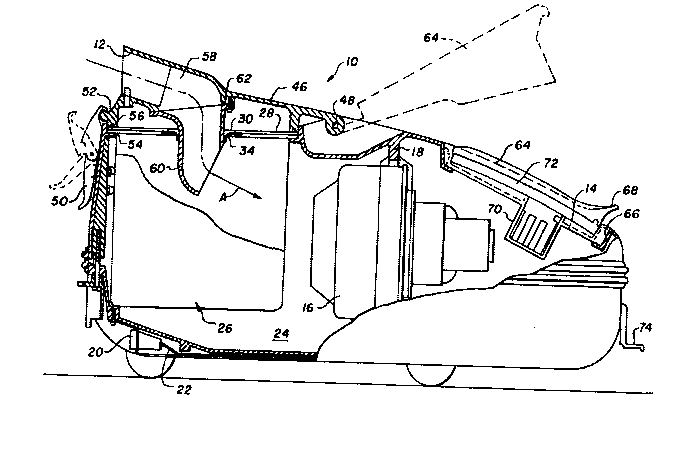
Figure 1 is a section through a vacuum cleaner
according to the present invention;
Figure 2 is a perspective view of a perforate dust
receptacle using in the vacuum cleaner of Figure l; and
Figure 3 is a further detail of the receptacle of
Figure 2.
The drawings show a vacuum cleaner comprising a body
10. There is an inlet 12 for dust laden air and an
outlet 14 in the body. An impeller 16 is located between
the inlet 12 and the outlet 14 mounted on a wall 18 of
the body 10. In the illustrated embodiment, the impeller
16 is an electric motor driving air in the direction of
the arrow A shown in Figure 1. There is a socket 20 from
which a cable 22 extends to the motor to supply power to
the motor.
There is a chamber 24 within the body 10 to receive
a perforate dust receptacle 26. In the illustrated
embodiment, as particularly shown in Figures 2 and 3, the
dust receptacle 26 is removable. It is held in place in
the chamber 24 during use but can be removed and,
B `~

2095298
usually, discarded together with the contained dust.
Receptacle 26 is shown in position in Figure 1 but is
also shown in Figures 2 and 3. Receptacle 26 has a
relatively rigid top 28 with a central opening 30. The
r~m~;n~er of the receptacle 26 is formed by a perforate
cylinder 32, typically of paper, attached to the top 28.
The opening 30 is formed with a flexible gasket 34 as
shown particularly in Figures 1 and 2. The top 28 is
provided with a handle 36 which is normally a flush fit
in a channel 38 provided in the top 28. There is a
finger opening 40 to facilitate gripping of the handle 36
to remove it from the position shown in Figure 2, where
it is flush with the surface of the top 28 to the raised
position shown in Figure 3. A flap 42 is also formed in
the top 28 again with an adjacent finger opening 44.
Figure 2 shows the position of the receptacle 26 when it
is in position in the body 10, for example as shown in
Figure 1. Figure 3 shows the position where the
receptacle 26 is to be discarded. The flap 42 is raised
using finger opening 44 and inserted within the gasket
34, thus sealing the opening 30 and the top 28 of the
receptacle 26.
Access to the chamber 24, to allow introduction and
removal of the receptacle 26 is through a door 46
pivotally mounted at 48 and locked by a catch 50 engaging
a recess 52 in the door 46. Inlet 12 is an intragal part
of the door 46. The body 10 is formed with flange 54
that contacts the under side of the top 28 of the
receptacle 26. The door 46 is formed with a
circumferential channel to receive an O-ring 56 that
contacts the upper surface of the top 28 of the
receptacle 26 to provide sealing.
There is an inlet passageway 58 extend from the
inlet opening into the chamber 26. As shown particularly
in Figure 1, the inlet passageway 58 is formed by a pipe

2095298
-- 4 --
60 attached to the inlet 12 at 62. Pipe 60 extends
through opening 30 in the relatively rigid top 28 of the
receptacle 26.
The opening 14 is closed with a perforate door 62,
pivotally mounted at 66 and raisable by pressing on
upst~n~;ng portion 68. A filter holder 70 extends
downwardly from the door 64 which is also closed by a
flat filter 72. This filtering removes any dust that may
have passed through the wall of the receptacle 26 and
ensures that no dust will enter the atmosphere.
A conventional foot switch 74 is shown attached to
the body to switch the motor 16 on and off.
To use the device according to the present invention
the door 46 is raised and a receptacle 26, in the
condition shown in Figure 2, is inserted into the chamber
24. The door 46 is closed. Catch 50 is engaged in
recess 52 and locked. The foot switch 74 is operated to
switch on the vacuum cleaner which is then operated by
the use of a flexible pipe (not shown) extending from the
inlet 12 to a head (not shown). Dust laden air is sucked
along the pipe, through the inlet 12, through the pipe 60
and against the wall of the receptacle 26. The direction
of the dust laden air, as shown by arrow A, is such that
there is a constant forced draft at least against a part
of the wall of the receptacle 26. This means that there
is no tendency of the dust to accumulate against that
wall. It tends to build in the receptacle 26 as shown in
Figure 1. The dust may be swirled within the receptacle
but that is not a problem. The important point is that
the dust-laden air is forced always against the clear
wall. The motor is thus not strained and the filtration
is effective. Should dust pass through the wall it is
collected in the filters 70 and 72 located ;n the outlet
14.

2095298
When the receptacle 26 is so full that the air
stream cannot maintains a clear portion of the wall of
the receptacle 26 catch 56 is released and door 46
raised. This simultaneously removes the pipe 60 from the
gasket 34 in the top of the receptacle 26. The flap 42
is raised, as shown in Figure 3, and inserted into the
opening. The handle 36 is then raised and the receptacle
26 removed and rejected, together with the contained
dust.
A fresh container 26, in the form shown in Figure 2,
is then inserted, the door 46 is closed, the catch 50
fastened and the cleaner is then ready for use.
The receptacle 26 may be made of paper with the
relatively rigid top 28 usually of cardboard. A rubber
annulus forms the gasket 34. The body 10 can be cased
from aluminum or from plastic.
In the preferred embodiment illustrated the cylinder
32 will be wholly perforate but it is envisaged that
there may just be a portion of the wall that is
perforate.
Filter 70 may be a simple carbon filter can be used
to ensure that no dust re-enters the atmosphere.

Dessin représentatif
Une figure unique qui représente un dessin illustrant l'invention.
États administratifs

2024-08-01 : Dans le cadre de la transition vers les Brevets de nouvelle génération (BNG), la base de données sur les brevets canadiens (BDBC) contient désormais un Historique d'événement plus détaillé, qui reproduit le Journal des événements de notre nouvelle solution interne.

Veuillez noter que les événements débutant par « Inactive : » se réfèrent à des événements qui ne sont plus utilisés dans notre nouvelle solution interne.

Pour une meilleure compréhension de l'état de la demande ou brevet qui figure sur cette page, la rubrique Mise en garde , et les descriptions de Brevet , Historique d'événement , Taxes périodiques et Historique des paiements devraient être consultées.

Historique d'événement

Description Date
Inactive : Périmé (brevet - nouvelle loi) 2013-04-30
Inactive : Lettre officielle 2007-01-16
Inactive : Paiement correctif - art.78.6 Loi 2007-01-03
Inactive : CIB de MCD 2006-03-11
Inactive : Grandeur de l'entité changée 2002-02-27
Accordé par délivrance 1997-05-06
Un avis d'acceptation est envoyé 1996-12-10
Exigences pour une requête d'examen - jugée conforme 1994-04-15
Toutes les exigences pour l'examen - jugée conforme 1994-04-15
Demande publiée (accessible au public) 1993-11-05

Historique d'abandonnement

Il n'y a pas d'historique d'abandonnement

Historique des taxes

Type de taxes Anniversaire Échéance Date payée
TM (brevet, 5e anniv.) - petite 1998-04-30 1998-04-07
TM (brevet, 6e anniv.) - petite 1999-04-30 1999-01-29
TM (brevet, 7e anniv.) - petite 2000-05-01 2000-02-28
TM (brevet, 8e anniv.) - petite 2001-04-30 2001-04-02
TM (brevet, 9e anniv.) - générale 2002-04-30 2002-02-19
TM (brevet, 10e anniv.) - générale 2003-04-30 2003-02-05
TM (brevet, 11e anniv.) - générale 2004-04-30 2004-03-23
TM (brevet, 12e anniv.) - générale 2005-05-02 2005-04-20
TM (brevet, 13e anniv.) - générale 2006-05-01 2006-04-18
2007-01-03
TM (brevet, 14e anniv.) - générale 2007-04-30 2007-04-12
TM (brevet, 15e anniv.) - générale 2008-04-30 2008-04-17
TM (brevet, 16e anniv.) - générale 2009-04-30 2009-03-24
TM (brevet, 17e anniv.) - générale 2010-04-30 2010-04-13
TM (brevet, 18e anniv.) - générale 2011-05-02 2011-04-19
TM (brevet, 19e anniv.) - générale 2012-04-30 2012-03-23
Titulaires au dossier

Les titulaires actuels et antérieures au dossier sont affichés en ordre alphabétique.

Titulaires actuels au dossier
KRISHAN KUMAR PURI
Titulaires antérieures au dossier
S.O.
Les propriétaires antérieurs qui ne figurent pas dans la liste des « Propriétaires au dossier » apparaîtront dans d'autres documents au dossier.
Documents

Pour visionner les fichiers sélectionnés, entrer le code reCAPTCHA :


Pour visualiser une image, cliquer sur un lien dans la colonne description du document. Pour télécharger l'image (les images), cliquer l'une ou plusieurs cases à cocher dans la première colonne et ensuite cliquer sur le bouton "Télécharger sélection en format PDF (archive Zip)" ou le bouton "Télécharger sélection (en un fichier PDF fusionné)".

Liste des documents de brevet publiés et non publiés sur la BDBC .

Si vous avez des difficultés à accéder au contenu, veuillez communiquer avec le Centre de services à la clientèle au 1-866-997-1936, ou envoyer un courriel au Centre de service à la clientèle de l'OPIC.


Description du
Document 
Date
(aaaa-mm-jj) 
Nombre de pages   Taille de l'image (Ko) 
Revendications 1994-02-25 2 78
Dessins 1994-02-25 2 73
Description 1994-02-25 5 218
Abrégé 1994-02-25 1 21
Abrégé 1997-03-23 1 20
Description 1997-03-23 6 232
Revendications 1997-03-23 3 89
Dessins 1997-03-23 2 50
Dessin représentatif 1998-10-25 1 24
Taxes 2003-02-04 1 38
Taxes 2001-04-01 1 40
Taxes 2002-02-18 1 39
Correspondance 2001-04-01 1 25
Taxes 2004-03-22 1 39
Taxes 2005-04-19 1 36
Taxes 2006-04-17 1 40
Correspondance 2007-01-15 1 14
Taxes 2007-04-11 1 37
Taxes 2008-04-16 1 35
Taxes 2010-04-12 1 36
Taxes 2011-04-18 1 67
Taxes 2012-03-22 1 66
Taxes 1997-02-16 1 48
Taxes 1996-02-04 1 39
Taxes 1995-02-09 1 37
Correspondance de la poursuite 1994-06-02 2 75
Demande de l'examinateur 1996-08-19 2 56
Correspondance de la poursuite 1996-11-03 4 126
Correspondance de la poursuite 1994-04-14 1 38
Correspondance reliée au PCT 1997-02-09 1 45
Courtoisie - Lettre du bureau 1994-05-24 1 42