Sélection de la langue

Search

Sommaire du brevet 2095364 

Énoncé de désistement de responsabilité concernant l'information provenant de tiers

Une partie des informations de ce site Web a été fournie par des sources externes. Le gouvernement du Canada n'assume aucune responsabilité concernant la précision, l'actualité ou la fiabilité des informations fournies par les sources externes. Les utilisateurs qui désirent employer cette information devraient consulter directement la source des informations. Le contenu fourni par les sources externes n'est pas assujetti aux exigences sur les langues officielles, la protection des renseignements personnels et l'accessibilité.

Disponibilité de l'Abrégé et des Revendications

L'apparition de différences dans le texte et l'image des Revendications et de l'Abrégé dépend du moment auquel le document est publié. Les textes des Revendications et de l'Abrégé sont affichés :

  • lorsque la demande peut être examinée par le public;
  • lorsque le brevet est émis (délivrance).
(12) Demande de brevet: (11) CA 2095364
(54) Titre français: RESONATEUR
(54) Titre anglais: RESONATOR STRUCTURE
Statut: Réputée abandonnée et au-delà du délai pour le rétablissement - en attente de la réponse à l’avis de communication rejetée
Données bibliographiques
(51) Classification internationale des brevets (CIB):
  • H01P 07/08 (2006.01)
  • H01P 01/203 (2006.01)
(72) Inventeurs :
  • TURUNEN, AIMO (Finlande)
  • JANTUNEN, HELI (Finlande)
(73) Titulaires :
  • LK-PRODUCTS OY
(71) Demandeurs :
  • LK-PRODUCTS OY (Finlande)
(74) Agent: MARKS & CLERK
(74) Co-agent:
(45) Délivré:
(22) Date de dépôt: 1993-04-22
(41) Mise à la disponibilité du public: 1993-11-09
Licence disponible: S.O.
Cédé au domaine public: S.O.
(25) Langue des documents déposés: Anglais

Traité de coopération en matière de brevets (PCT): Non

(30) Données de priorité de la demande:
Numéro de la demande Pays / territoire Date
922102 (Finlande) 1992-05-08

Abrégés

Abrégé anglais


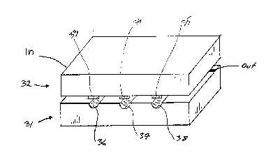
The present invention relates to a resonator structure com-
posed of two dielectric pieces. On the upper surface of a
first piece (1) is provided a groove (7) extending across
the entire surface and coated with an electrically conduc-
tive agent, said coating being at least in one end con-
nected with an electrically conductive coating serving as a
ground plane, so that the groove (7) forms a transmission
line resonator. On the upper surface of the second piece
(2) is provided a conductive strip (9) running in the mid-
dle of the surface, said strip forming a transmission line
resonator. The pieces (1, 2) are placed with the upper sur-
faces thereof against each other and attached to each other
so that the groove (7) and the strip (9) are against one
another in parallel, whereby the groove and the strip to-
gether form a resonator.

Revendications

Note : Les revendications sont présentées dans la langue officielle dans laquelle elles ont été soumises.


PCT/SE91/00755
CLAIMS
1. A wheelchair for handicapped people including a frame struc-
ture, which is carried on chair-rolling devices and which in
turn carries a seat and back-support, the seat and the frame
structure being constructed so that the lower part of the frame
can be introduced beneath a bed, sofa, toilet or like seating
and/or lying arrangement, with the seat located above said
arrangement, c h a r a c t e r i z e d i n that the seat
(8) is divided longitudinally, preferably along a centre line,
and in that the seat parts (9, 10) are so journalled to the
frame structure (1) as to enable said parts to be swung out
individually on respective sides of the frame structure.
2. A wheelchair according to claim 1, c h a r a c t e r i z e d
i n that the seat (8) includes two seat members (9), each
having a respective back-support member (10) arranged so that
the seat with back-support is divided along a centre line
in the longitudinal direction of the wheelchair, and in that
the seat members are each pivotally connected to a respective
upper frame part (6) by means of hinge devices (7).
3. A wheelchair according to claim 1 or 2, c h a r a c t -
e r i z e d i n that the seat members (9) can be brought
together partially in a manner to substitute for a toilet
seat.
4. A wheelchair according to claim 1, 2 or 3, c h a r a c t-
t e r i z e d i n that respective seat members (9) can be
raised and lowered independently of one another.
5. A wheelchair according to claim 4, c h a r a c t e r-
i z e d i n that the seat members (9) can be raised and lowered

PCT/SE91/00755
either by means of blockable gas springs (11) with associated
latch means, wherein the lifting force of each spring
preferably corresponds essentially to half of the weight of the
patient, or by means of electric motors.
6. A wheelchair according to claim 2, 3, 4 or 5, c h a r a c-
t e r i z e d i n that the hinge means (7) are positioned
obliquely so that the seat members (9) will rise when swung
outwardly and will fall into place and therewith lower when
swung inwardly.
7. A wheelchair according to claim 7, c h a r a c t e r -
i z e d i n that the frame structure (1) and the seat (8)
form a substantially horizontally open U-shaped configur-
ation, where the seat (8) and, when appropriate, an upper
part (6) of the frame structure on the lower part (3) of said
frame structure form the legs of said configuration.

WO 92/08430 6 PCT/SE91/00755
8. A wheelchair according to Claim 7, c h a r a c t e r i z e d in
that the frame structure (1) and the seat (8) form a substantially
horizontally opening U-shaped configuration where the seat (8) and,
when appropriate an upper part (6) of the frame structure on the
lower part (3) of said frame structure form the legs of said configura-
tion.

Description

Note : Les descriptions sont présentées dans la langue officielle dans laquelle elles ont été soumises.

YY~ 9~/08~30 ,~ ", ~ ~C~/S~ 0
l y L~
A wheelchair where the seat is ii~iie~ longituii~all~.
me E~resent ~ion relates to a wheelchair fc7r the h~ndicaE~ped,
cc~?risin3 a frame st~uch:re ~ich is carried b~ chai~ rolling
devices an~ ~ich supports a c~hair seat.
It is ~cnawn that har~icapp~3d people find it clifficult to cli~ fr~
their bed irrto a wheelchair and to clilab fram the ~ eelc~hair onto a
toilet or water close~. In the c a of ycunger pecple with well-
developed m~scles, this pr~blem is c~eroome relatively easily for a
number of years, alt ~ with time the shculder mLscles of the
person co ~ are liable to k~xx~me strained and tired therewith
often rec~liring the assistance of a nurse or like attendant, par-
tic~larly as the~weight of the hecxLk~a~ped person increlses.
m e present invention relates to a wheelchair which provides a svlution
to the aforesaid problem and enables handicapped personS to m~ve Lnto
and ~rcm the wheelc ~ Lr without appreciable effort.
~ e i ~ ion thus relates to a wheelchair for the handicapped,
ccmprisin~ a frame et~ ture which is czrried ~y chair~r~lling devices
and which, in turn, carries a seat and ~ means.
The wheelchair is mainly cbElrac~erized in that the seat is divided in
its longit~din21 di~ecticn, preferably alcng a ce~tre l me, and is so
journalled to the frame stxucture that the s ~ parts of the seat
can ~e swung cut on re5pective sides of the frame, independently of one
another.
The invention will ncw be des~ribed in ~ore detail w1th reference to
an exemplifying ewtodiment thereof and also with referenLe to the
accompanying drawings, in which
- Figur2 1 is a vertical, central longitudina~ ~ection view thrcugh
a fir~t e=bodi=ent of ~n inventive wheelchair whose frame struc-
ture is oDnstructed so as ~o enable the chair to be ~ved cver a
ked while enabling, at t~e same ti~e, part of the c~Iir t~ ~e
~serted beneath the ~d;

~V ~ ~ 2 / ~ p ~l! 5 3 9
2119~)b9~ 2
- Figure 2 illus~ates the ~eelchair of Figure 1 in p~tive;
- Figure 3 ill~tes the wheelchai:r s~wn in Fig~e 1 seen fr~m
above in said Figure and sh~1s the seat ~Esr~S in a fully
~twa~y swung position, and also shaws in hq~ lines the
seat nE~rs ~n a fully ca~i~ position and a partially aut
wardly swur~ positia~;
- Figure 4 illustrates the wheelchair of Figure 1 seen from the
left in said Figure, and show~ the seat with both seat ~ s
positi~ned at mL~Lally the same height; and
- Figure 5 illustrates the wheelchair of Figure 4, with one seat
member raised a~ove the other.
Shcwn in Figure 1 is a frame struc*ore 1 of which one-hal-f is shown
Ln the Figure and of which each half incl c a vertical part 2 which
is connected to a sobftantially horizont31 lower part 3 supported on
casters 4. A mLveable perisoope-like part 5 of the v~rti~l frame
part ~, such as a tubul æ part 5, is connected to a sub6tantially
h~rizontal u~per frame part 6, which is pivotally conneoted to a seat
memker 9 forming part of the seat 8 of the wheel~hair by means of
appropriate hinge dviDes 7. l~e seat member 9 is, in turn, connected
25 to a ~ack-support ~ r 10 connected to in the wheelchair seat.
. :
qhe wh~lc~hair seat is t~s divided into twc seat oamponer~ts in the
longitid~al direction of the whce:Lc~air, E~referably along a centre
line 8' ~ Figure 3, each seat part oamE~ri5ing t~ther tw~ seat
30 co~ts an~ t~ck~rt c~ts, ~d seat c~s w~th
conn~tirq ~ck~rt c~s beins~ oapable of being sw~
ir~leF r~ ntly to re ~ tive sides of tlne wheel~hair, as illustrated
m Figure 3. ~cconding ~o one preferred ewbcdlment of the invention,
~he seat c= }onents, when k~ ht partially togather, can su~stitute
for a toilet seat~
Respecti~e seat parts can ~e raised an~ lower~d independently of
each okher. In the case of the illustrated embod m ent, there is

- ~,V{3 9~ 843~ 3 Drl /SE:s~ 7~
arranged in ea~ of the mNeable p~ricop~li~ce parts 5 a blockable
gas s~rin~ 11 ~v~ded with a manipulatir~ knab 12 by roeans of ~ich
the parts 5 can be lo~ked ~n &elec~d positi0ls. qhe liftir~ fo~e
exerted ~y each sE~ring will ~referably correspond ess ~ ally to half
of th~ weight of a patient. It is also conceivable to raise and
lower the seat parts wqth the aid of electric ~ors.
A~cording to one preferred e=~sxLuDe-t of the invention, the ~ e
devices 7 are obliquely po5itioned SO that when the seat me~kers 9
w~ e raised whRn swung oL~ nds and will fall into plaoe when
sw~ i~1ards.
The reference 13 identifies a crcss strut which connects the two
sides of the frame struct~re.
Accor~ing to o~e preferred e trrLIncnt, the seat an~ the frame struCtDre
are arranged so that a lcwer part of the frame can be inserted keneath
a ~ed, sofa, toilet or like sitting and/or lying arr ~ nt with the
seat positioned above the slme. In this case, it is preferxed that the
frame struLture and the seat form a substantially horizontal, U-
shaped configuration, of which the seat and, when appropriate, an upper
part of the frame struct~re or the lower part of the frame structure
form the legs of said ccnfiguration.
The m3nner in w~ich the inNentive wheelchair operates will ~e under-
stood in all cssentials frcm the aforegDing. When a person wishes to
leave the bed or the like, it is a ~ d that he or she is able to
sit up and to turn ~o as to ke seated across the bed with his or her
feet resting on the flocr. The whÆelchair, which is within easy
reach, is mcNed in over the ked, with the seat and ~ack-s ~ rt
memkers swung cutwards. By shif~ing his or her ~ody ~ ~ht from one
side to the other, the patient is able to ~ove the seat members 9 in
~eneath his ~r h~r ~ody, first on one side and then on the other. The
person is then able to li~t himsel~ or herself free frcm the ~ed,
with the aid of the gas springs or liXe dsvices. The proccdure is
essentially the same ~n the case o~ Gther seating and/or lying arrange-
m~nts.

W ~3 ~ 2 / ~ J () D ~ S S O ~ 7 1;
It will be evident fr~n the aforegong tha~ the ~eelchair will enable
nursing ~s~l to move a patient f~m a bed to a toilet, a~ vice
versa, without needir~ to lift the patient. If the wheelchair is
fitted with ~tor driven wheels, the patient is able to ~nanage ~y
hi~elf, without assistance. - -
Altho~ the irr~tion has been described with ref~nce to exempli-
fying en~di~ts th~eof, it will be understood that changes and
n~difications can be made without departir~ fram the concept of the
10 ~venti~.

Dessin représentatif
Une figure unique qui représente un dessin illustrant l'invention.
États administratifs

2024-08-01 : Dans le cadre de la transition vers les Brevets de nouvelle génération (BNG), la base de données sur les brevets canadiens (BDBC) contient désormais un Historique d'événement plus détaillé, qui reproduit le Journal des événements de notre nouvelle solution interne.

Veuillez noter que les événements débutant par « Inactive : » se réfèrent à des événements qui ne sont plus utilisés dans notre nouvelle solution interne.

Pour une meilleure compréhension de l'état de la demande ou brevet qui figure sur cette page, la rubrique Mise en garde , et les descriptions de Brevet , Historique d'événement , Taxes périodiques et Historique des paiements devraient être consultées.

Historique d'événement

Description Date
Le délai pour l'annulation est expiré 1999-04-22
Demande non rétablie avant l'échéance 1999-04-22
Réputée abandonnée - omission de répondre à un avis sur les taxes pour le maintien en état 1998-04-22
Demande publiée (accessible au public) 1993-11-09

Historique d'abandonnement

Date d'abandonnement Raison Date de rétablissement
1998-04-22
Titulaires au dossier

Les titulaires actuels et antérieures au dossier sont affichés en ordre alphabétique.

Titulaires actuels au dossier
LK-PRODUCTS OY
Titulaires antérieures au dossier
AIMO TURUNEN
HELI JANTUNEN
Les propriétaires antérieurs qui ne figurent pas dans la liste des « Propriétaires au dossier » apparaîtront dans d'autres documents au dossier.
Documents

Pour visionner les fichiers sélectionnés, entrer le code reCAPTCHA :


Pour visualiser une image, cliquer sur un lien dans la colonne description du document (Temporairement non-disponible). Pour télécharger l'image (les images), cliquer l'une ou plusieurs cases à cocher dans la première colonne et ensuite cliquer sur le bouton "Télécharger sélection en format PDF (archive Zip)" ou le bouton "Télécharger sélection (en un fichier PDF fusionné)".

Liste des documents de brevet publiés et non publiés sur la BDBC .

Si vous avez des difficultés à accéder au contenu, veuillez communiquer avec le Centre de services à la clientèle au 1-866-997-1936, ou envoyer un courriel au Centre de service à la clientèle de l'OPIC.

({010=Tous les documents, 020=Au moment du dépôt, 030=Au moment de la mise à la disponibilité du public, 040=À la délivrance, 050=Examen, 060=Correspondance reçue, 070=Divers, 080=Correspondance envoyée, 090=Paiement})


Description du
Document 
Date
(aaaa-mm-jj) 
Nombre de pages   Taille de l'image (Ko) 
Revendications 1993-11-08 4 126
Dessins 1993-11-08 2 27
Description 1993-11-08 8 326
Abrégé 1997-03-13 1 24
Dessin représentatif 1998-11-03 1 5
Courtoisie - Lettre d'abandon (taxe de maintien en état) 1998-05-19 1 186
Taxes 1997-03-19 1 61
Taxes 1995-04-06 1 43
Taxes 1996-03-19 1 55
Correspondance reliée au PCT 1993-04-29 2 70
Courtoisie - Lettre du bureau 1993-08-04 1 32