Note : Les descriptions sont présentées dans la langue officielle dans laquelle elles ont été soumises.
- BACKGROUND OF THE INVENTION 2 0 9 ~ 51~
Field of the Inve~tion
This invention relates to a process and apparatus
for combustion of carbon black and natural gas in a
combustion chamber to produce a luminous flame and maintain
low-pollutant emissions. In particular, this invention
relates to a process and apparatus for combustion of a
carbon black enriched gaseous hydrocarbon fuel.
Description of the Prior Art
In many high temperature industrial applications,
such as glass melting furnaces, it is desired to provide a
highly luminous flame to improve radiant heat transfer ~ate
to the furnace load resulting in increased furnace
production rate and increased furnace thermal efficiency.
When generating such highly luminous flames, environmental
considerations require that pollutant emis~ions, including
nitrogen oxide emissions, be maintained at a low level.
Highly luminous flames are typically generated in the
combustion of both coal and fuel oils. However, combustion
of solid and liquid fuels is difficult to control and
typically results in high pollutant emission rates requiring
treatment of the flue gases to reduce pollutant emissions to
an acceptable level. The combustion of gaseous hydrocarbon
fuels, such as natural gas, produces flames having lower
luminosity than flames produced by solid or liquid fuel
combustion. However, combustion of gaseous hydrocarbon
fuels generally produces substantially lower pollutant
emissions than the combustion of solid or liquid fuels, and
thus, gaseous hydrocarbon fuels, such as natural gas, are
preferred for many industrial applications.
Methods for producing highly luminous flames in
the combustion of gaseous hydrocarbon fuels are known in the
CT-104 2 esb/3
.
209~61~
prior art. One such method is simply to combust the gaseous
hydrocarbon fuel under fuel rich conditions, thereby
generating large amounts of carbon monoxide and some soot,
both of which have high emissivities. However, this
technique also produces flue gases containing h~gh levels of
pollutant emissions which must be removed, or otherwise
eliminated, before being exhausted into the atmosphere.
U.S. Patent 4,761,132 teaches a two-stage process
and apparatus for producing a highly luminous flame ln which
a portion of the total fuel to be combusted is cracked in a
cracking chamber under fuel rich conditions with oxygen rich
gas and the cracked products including uncracked fuel,
carbon monoxide, hydrogen, carbon dioxide, water, soot, some
inerts, and a second portion of fuel are combusted in a
combustion chamber.
U.S. Patent 3,656,878 teaches a high luminosity
burner in which products of combustion, which include soot
particles, are burned with a second fuel such as natural
gas. Incomplete combustion of a first fuel in a diffusion
flame is used to produce a controlled quantity of solid soot
particles which, along with other products of the diffusion
flame combustion, move downstream where they are again
combusted with a gaseous fuel in the presencs of excess air
to produce a secondary flame which has luminosity greater
than the luminosity normally associated with the combustion
of gaseous fuels.
U.S. Patent 3,827,851 and related U.S. Patent
3,859,935 relate to a combination oil, gas and/or solids
burner. The '851 patent teaches operation of the burner
apparatus with oil, gas and/or particulate solid material in
which the particulate solid fuel is preferably wood,
plastic, coal or other suitable substitutes which can be
CT-104 3 esb/3
209~615
formed into relatively small particle sizes so that the fuel
burns in suspension. The particulate solid fuel is
introduced into the combustion chamber by either blowers,
screw augers, conveyer belts or the like. The '935 patent
teaches a process for u~ing the apparatus taught by the '851
patent in which a combination burner structure i~ provided
with an inner burner for oil and/or gaseous fuels, mounted
with a refractory primary combustion chamber and a wood air
mixture passageway surrounding the oil and/or gas burner.
During the process, particulate combustible material is
introduced into the combustion chamber after having been
dried.
U.S. Patent 4,015,951 discloses fuel pellets for
burning in industrial applications and a method for making
such fuel pellets from organic fibrous materials. U.S.
Patent 4,249,471 teaches a method and apparatus for
producing a combustible mixture of a solid fuel pellet made
from organic fibrous material, as disclosed in the '951
patent, and a flammable gas or liquid fuel in which a blower
forces the pulverized solid fuel into a conduit, the stream
of pulverized fuel being tangentially added to the gaseous
fuel entering a center conduit of the apparatus.
U.S. Patent 4,780,136 teaches a method of
injecting combustion resistant fuel into a blast furnace in
which a measured portion of combustion resistant fuel is
injected into a stream of hot blast air and a gaseous fuel
is in~ected into the hot blast air independent of the
pulverized fuel, the gaseous fuel being supplied to an outer
peripheral area of the pulverized fuel.
SUNMARY OF THE INVENTION
It is an ob~ect of this invention to provide a
process and apparatus for combustion of carbon black and a
CT-104 4 esb/3
209~
gaseous hydrocarbon fuel in a combustion chamber, ~n
particular a glass melting furnace, to produce a luminous
flame while maintaining low pollutant emissions. For
purpose3 of this disclosure, carbon black is distinguishable
from ~oot on the basis that carbon black contains more than
about 97% carbon particles whereas soot is only about 90%
carbon particles, the balance being other gaseous
hydrocarbons and oils.
This and other objects are achieved ~n accordance
with the process of this in~ention in which carbon black
particles are entrained in a carrier fluid, preferably a
gaseous hydrocarbon fuel, to form a carbon black/carrier
fluid mixture. The carbon black/carrier fluid mixture is
injected through a center nozzle of a fluid injector into a
combustion chamber, the fluid injector having an outer
nozzle concentrically disposed around the center nozzle
forming an annular chamber between the center nozzle and the
outer nozzle. A gaseous hydrocarbon fuel, preferably the
same type of gaseous hydrocarbon fuel used as said carrier
fluid, is injected through the annular chamber into the
combustion chamber, forming a carbon black enliched gaseous
hydrocarbon fuel in the combustion chamber. The carbon
black enriched gaseous hydrocarbon fuel is mixed with
combustion air introduced directly into the combustion
chamber, forming a fuel/air mixture with a fuel/air ratio
between about 0.02 and about 1.4 on a volume basis depending
upon the gaseous hydrocarbon fuel used, and the resulting
mixture i8 ignited.
The apparatus for combustion of a carbon black
enriched ga~eous hydrocarbon fuel in accordance with this
invention comprises a center nozzle having a center nozzle
tip secured to the outlet end thereof,~an outer nozzle
CT-104 5 esb/3
2~96615
concentrically disposed around the center nozzle and forming
an annulus between the center nozzle and the outer nozzle,
means for longitudinally adjusting the relative position of
the center nozzle tip and the outlet end of the outer
nozzle, means for entralning the carbon black in the carrier
fluid in communication with the center nozzle upstream of
the outlet end of the center nozzle, and means for
lntroducing a gaseous hydrocarbon fuel into the annulus
connected to the outer nozzle.
The center nozzle tip secured to the outlet end of
the center nozzle has an outer diameter which converges
toward the longitudinal axis of the center nozzle in a
direction away from the outlet end of the center nozzle and
toward the combustion chamber. The outer nozzle has an
inner diameter toward the outlet end of the outer nozzle in
the form of a venturi. By ad~usting the relative po~ition
of the center nozzle tip and the outlet end of the outer
nozzle, the center nozzle tip is displaceable within the
venturi formed by the inner diameter of the outer nozzle,
thereby adjusting the flow of gaseous hydrocarbon fuel
through the annulus around the center nozzle.
Means for entraining the carbon black in the
carrier fluid, in accordance with one embodiment of this
invention, comprise a carbon black storage vessel, means for
controlling the amount of carbon black entrained in the
carrier fluid in communication with the carbon black storage
vessel, means for reducing the carbon black to particle
form, and conveyer means for mixing the carrier fluid with
the carbon black particles to form a carrier fluid/carbon
black mixture and convey the carrier fluid/carbon black
mixture into the center nozzle.
CT-104 6 esb/3
2~9~61~
BRIEF DESCRIPTION OF THE DRAWINGS
These and other features of the invent~on will
become more apparent from the following detailed description
taken in conjunction with the drawings, wherein:
Fig. 1 is a schematic flow diagram of the process
for combustion of carbon black enriched gas60us hydrocarbon
fuels in accordance with one embodiment of this invention;
Fig. 2 is a schematic flow diagram of the process
for combustion of carbon black enriched gaseous hydrocarbon
fuels in accordance with one embodiment of this invention as
applied to an end-fired glass regenerative furnace;
Fig. 3 is a schematic diagram in partial cross
section of an apparatus for combustion of a carbon black
enriched gaseou~ hydrocarbon fuel in accordance with one
embodiment of this invention;
Fig. 4 is a schematic dlagram of a burner tip for
the apparatu~ shown in Fig. 3; and
Fig. 5 i8 a schematic diagram of a center nozzle
tip for the apparatus as shown in Fig. 3.
DESCRIPTION OF PREFERRED EMBODIMENTS
In the process for combustion of carbon black
enriched gaseous hydrocarbon fuels in accordance with one
embodiment of this invention as shown in Fig. 1, carbon ;
black, preferably in the form of pellets, is conveyed from
storage bin 10, preferably by gravity, to a means for
weighing the carbon black which permits, by weight
differential, accurate feeding of a predetermined quantity
of carbon black to a dense phase pneumatic conveying system.
The carbon black i8 pulverized, if necessary, by means for
pulverizing 12 such as a pneumatic pulverizer or hammermill,
after which it is transferred to the dense phase pneumatic
conveying system in the form of pneumatic conveyer 13.
CT-104 7 esb/3
209~61a
A carrier fluid, preferably a gaseous hydrocarbo~
fuel, is introduced into pneumatic conveyer 13 where it
picks up carbon black particles and conveys them to the
center nozzle of burner 14. The gaseous hydrocarbon fuel is
also introduced into the outer nozzle of burner 14 for
in~ection into the combustion chamber together with the
mixture of carrier fluid and carbon black flowing through
center nozzle 24 of burner 14.
Fig. 2 shows a specific example in accordance with
one embodiment of this invention as applied to an end-fired
regenerative furnace 15. For purposes of this example, the
left side port 16 is firing and right side port 17 is off.
Carbon black pellets, wetted bedded carbon black, stored in
super6ack 19 is transferred by gravity to loss-in-weight
feeder 20 which accurately feeds a predetermined quantity of
carbon black to the 6ystem. The measured carbon black is
fed to a pressure vessel, namely, transporter 18. An inert
gas, preferably nitrogen, pressure seal 21 between loss-in-
weight feeder 20 and transporter 18 is necessary to prevent
any air lea~age into the system. To take advantage of the
cyclic nature of regenerative furnaces, two .:ransporters 18,
22 are used such that when left side port 16 of end-fired
regenerative furnace 15 is firing, transporter 18 is used
for the conveying cycle while transporter 22 is being
filled. When firing in end-fired regenerative furnace 15 is
switched from left side port 16 to right side port 17,
transporter 22 is used for conveying the carbon black to
burner 29 while transporter 18 i8 filled with carbon black.
As left side port 16 commences firing, transporter
18 which was previously filled is activated. A gaseous
hydrocarbon fuel, preferably natural gas, preferably at less
than 25 psig, required to convey a measured quantity of
CT-104 8 esb/3
20~6~1~
.
carbon black to burner 14 in left side port 16 is gradually
introduced through the top of transporter 18. The gaseous
hydrocarbon fuel mixes with the carbon black in tra~sporter
18 and forces the carbon black enriched gas through
conveying line 23 to center nozzle 24 of burner 14. The
process continues in this fashion until transporter 18 and
conveying line 23 are free of carbon black. A sufficient
time is provided to purge transporter 18 and conveying line
23.
A pressure switch is used to monitor the pressure
of the carrier fluid in transporter 18 and is activated at a
predetermined low pressure setting to turn off the high
pressure carrier fluid supply to transporter 18 and allow
the residual fluid volume to transfer into flare off line 25
vented to furnace 15 at a suitable location. The pressure
switch also activates a three port valve 26 at burner 14
which allows cooling air to ~low into center nozzle 24 of
burner 14 during the period when left side port 16 is not
firing. The amount of cooling air provided by cooling air
supply 27 is set on the basis of furnace firing rate and
flue volume.
Upon completion of the firing cycle in which left
side port 16 is fired, firing is switched to right side port
17 utilizing transporter 22 conveying line 2C:, 3-way valve
30 and burner 29. Carrier fluid for both firing cycles is
provided to transporters 18, 22 from carrier fluid supply
31. By a periodic switching, carrier fluid supply 31
provides a remaining portion of carrier fluid, about 25
percent to 100 percent of the total carrier fluid required,
to outer nozzle 32 of burner 14 for the duration of the
firing cycle through left side port 16. At the end of the
firing cycle, the carrier fluid is switched to right side
CT-104 9 esb/3
2~9~61~
port 17, which would now be in a firing mode.
Although specifically shown as applied to an end-
fired regenerative furnace, the process of this invention
may be applied to other furnaces including side-fired
regenerative furnaces, unit melters, oxy/fuel furnace~ and
recuperative furnace~.
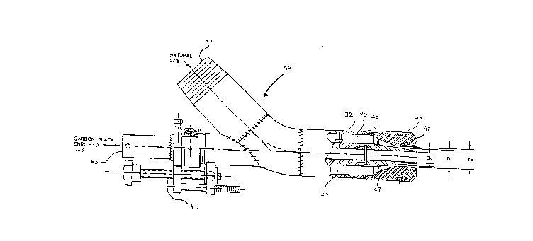
Fig. 3 shows a schematic d~agram of an apparatus
for combustion of a carbon black enriched gaseous
hydrocarbon fuel in accordance with one embodiment of this
invention. The apparatus for carbon black enriched
combustion can be utilized on side- and end-fired
regenerative furnaces. Hot combustion air is supplied from
the furnace regenerators and delivered to the furnace
through a furnace port. Burner 14, 29 introduces a carbon
black enriched carrier fluid and a remaining fuel at the
port, from either an over-port position, a through-port
position, a side-of-port position, or an under-port
position.
Burner 14 features two separate orifices for
carrier fluid in;ection. The carbon black enriched carrier
fluid, preferably comprising about 0 to about 75 percent of
a total amount of qaseous hydrocarbon fuel, preferably
natural gas, to be burned, is injected from center nozzle 24
through center nozzle tip 40. The remaining gaseous
hydrocarbon fuel, about 25 to 100 percent of the total
gaseous hydrocarbon fuel combusted, iB in~ected through an
annulus formed by center nozzle tip 40 and the outlet end of
outer nozzle 45, typically in the form of burner tip 41.
The ratio of carbon black particles to natural ga~ varies
between about 0.0001 to about 0.05 pounds per cubic foot of
natural gas. The annulus formed by center nozzle tip 40 and
burner tip 41 iB ad~ustable to maintain a given flame length
CT-104 10 esb/3
2~9~
and shape within a specific furnace by altering t~e gaseous
hydrocarbon fuel velocity. The annular area is varied,
preferably in the range of 2.5:1 to 3:1 to allow optimum
burner operation. To adjust the annulus, center nozzle 24,
and hence center nozzle tip 40 are longitudinally adjustable
in and out of burner tip 41 by ad~ustment m~chanism 44.
Center nozzle tip 40 is provided with a tapered outer
diameter 47 which tapers toward the outlet of burner tip 41.
This tapered geometry permits the annular area surrounding
center nozzle tip 40 to be varied as center nozzle tip 40 is
longitudinally adjusted in and out of burner tip 41 by
adjustment mechanism 44.
Fig. 4 shows a design for burner tip 41 in
accordance with one embodiment of this invention for natural
gas firing at flow rates between about 500 to about ~4,000
standard cubic feet per hour. Burner tip 41 is mounted to
the end of outer nozzle 32 having an internal diameter Dlp
which ranges from about lk inches to about 4 inches,
depending on firing rate. Burner tip 41 has a throat
section of diameter Do and a length of DJ2 downstream of
throat section 50 is recovery section 51 having about a 5-
divergence and a length D~2. The approximate range of Do
for various firing rates varies between about 0.3 inches to
about 3 inches.
Fig. 5 shows center nozzle tip 40 which is
attached to the outlet end of center nozzle 24. The most
critical dimension of center nozzle tip 40 is designated as
Dl which dimension qenerates a minimum annular area through
which the fuel flows through burner tip 41. Movement of
center nozzle tip 40 over a range approximat61y equ;valent
to the diameter Do of throat section 50 changes the annular
flow area and velocity of the gaseous hydrocarbon fuel
CT-104 11 esb/3
209~15
leaving the burner. The tapered external geometry, 7~ and
10- as shown, allows the variation of annular area formed by
Do and D~. The minimum area i5 obtained when center tip
nozzle 40 i8 flush with the burner tip 41 and annular area
between Do and D~ i8 at a minimum. When center nozzle tip
40 i8 retracted back in burner tip 41, the flow area through
burner tip 41 open~ up to a maximum, the re~ulting area no
longer being annular but rather being a solid ~et of
diameter Do~
Center nozzle tip 40 also serves the function of
conveying carbon black enriched carrier fluid through burner
tip 41 into the furnace. The internal diameter of center
nozzle tip 40, designated as Dc, is variable in the range of
about 0.2 inches to about 1.5 inches depending on the firing
capacity and furnace firing configuration. The opening in
center nozzle tip 40 having diameter Dc also serves the
purpose of cooling the apparatus during the off-side firing
of a regenerative furnace. A cooling air flow, about S to
about 20 standard cubic feet per minute, depending on the
burner firing capacity, is directed through center nozzle
tip 40 when burner 14, 29 is not firing.
Center nozzle tip 40 is secured to the outlet end
of center nozzle 24 for conveying the carbon black enriched
carrier fluid. The outer diameter DtU of center nozzle 24
is preferably in the range of about 1 inch to about 3 inches
depending on the firing capacity, furnace type and firing
configuration. The inside diameter of center nozzle 24 is
preferably the same as the inside diameter of center nozzle
tip 40, namely Dc, which iB variable in the range of about
0.2 inches to about 1.5 inches.
While in the ~oregoing specification this
invention has been described in relation to certain
CT-104 12 esb/3
2~9~
preferred embodiments thereof, and many details have been
set forth for the purpoæe of illustration, it will be
apparent to those skilled in the art that the invention is
susceptible to additional embodiments and that certain of
the details de~cribed herein aan be varied considerably
without departing from the ba~ic principals o~ the
invention.
CT-104 13 esb/3