Note : Les descriptions sont présentées dans la langue officielle dans laquelle elles ont été soumises.
0 6
SOFT TORIC LENS FOR CORRECTION OF ASTIGMATISM
BACKGROUND OF THE INVENTION
1. Field of the invention:
The present invention relates to a toric
contact lens for astigmatic correction.
2. Brief description of the prior art:
As well known to those of ordinary skill
in the art, the angular orientation of toric contact
lenses must be maintained constant to prevent
deviation of the astigmatic correction from the
desired axis.
.~
To prevent rotation thereof, prior art
i toric contact lenses comprise an anterior surface
formed with a prismatic central optical ~one adapted
- to increase the thickness of the lower portion of the
lens. The additional weight in the lower portion of
the lens then produces an effect of ballast that
3 , maintains the lens in the required angular
orientation. A prismatic central optical zone
presents the drawback of producing prismatic
aberrations that r~duce the optical quality of the
lens and therefore the visual acuity of the patient.
Moreover, the prismatic central optical zone increases
the thickness of the lens to thereby recluce both the
,
,
~,
' . : ~ ' :: : .' . . : . : '
:: 2 ~ 9 ~
.
- comfort of the patient's eye and the transmission of
oxygen to the eye's cornea. As well known to those
skilled in the art, tolerance of the eyes to contact
lenses reduces with the thickness of the lenses.
Another prior art method to prevent
rotation of a toric contact lens is described in
United States patent N 5,020,898 ~Townsley). This
method consists of forming the anterior surface of the
lens with peripheral upper and lower non s~mmetrical
prismatic zones creating an effect of ballast. More
specifically, this prismatic geometry increases the
thickness of the lower portion of the lens and the
additional weight of this lower portion maintains the
lens in the desired angular position. The drawbacks
of this method are the production of prismatic
aberrations in the lens's optical system and the
`' increase of thickness in the central region of the
lens.
A further prior art method to prevent
-' rotation of the toric contact lens consists of forming
1 the lens with two diametrically opposed thinned zones.
Upon movement of the eyelids on these thinned zones,
the eyelids tend to push th thicker central portion
of the lens to ensure stability thereof. A major
disadvantage of this method is that the lens should be
made thicker in the central region to enable formation
of efficient thinned zones.
i
~'
: 3
2~9~70~
:;
OBJECT OF THE INVENTION
An object of the present invention is
therefore to provide a toric contact lens for
astigmatic patients that eliminate the above mentioned
. drawbacks of the prior art.
. .
SUMMARY OF THE INVENTION
More specifically, in accordance with the
present invention, there is provided a toric contact
`. 15 lens for astigmatic correction, comprising a
: peripheral edge, a concave posterior surface to be
. applied to a patient's eye and formed with a
, substantially central toric zone to optically correct
asti~matism of the patient's eye, and a convex
~i 20 anterior surface symmetrical about an horizontal plane
j of symmetry.
:
The convex anterior surface of the toric
-, contact lens of the invention comprises:
.' 25 a substantially central optical zone; and
. a pair of upper and lower perip~neral
~ . prismatic zones situated outside the central optical
zone and symmetrical about the horizontal plane of
symmetry, wherein each prismatic zone dafines an apex
: 30 along the peripheral edge of the lens, and wherein the
:~ lens has, in the region of each prismatic zone, a
thickness that gradually increases from this apex
toward the central optical zone;
~!
:
:..
f
.,, . ~ . . ;i . . `. ,
: 209~7~
'.!
c whereby sliding movement of the eyelids
of the patient on the upper and lower pxismatic zones
pushes these prismatic zones to procluce a stabilizing
effect that maintains the contact lens on the
5 patient's eye in a desired, predetermined angular
orientation.
In accordance with preferred embodiments
of the present invention, the central optical zone is
10 spherical, the upper and lower prismatic zones have
the general configuration of a crescent moon, and the
anterior surface further comprises an intermediate
aspheric zone surrounding the central optical zone and
forming a smooth transition surface between this
15 optical zone and the upper and lower peripheral
; prismatic zones.
.. ~
Advantageously, the anterior surface is
symm,etrical about a vertical plane of symmetry, the
upper and lower prismatic zones are ~ymmetrical about
this vertical plane of symmetry, and the anterior
surface further comprises peripheral spherical zones
symmetrical about the vertical plane of symmetry, the
lens being thinned in the region of these peripheral
j 25 spherical zones.
The combination of a spherical central
optical zone, an intermediate aspheric zone, upper and
lower peripheral prismatic zones and peripheral
thinned zones enables production of a toric contact
lens that is thin and free from prismatic aberrations.
'
i
.: :, . . . - :.; : . :
:
:: 2~9~7~
..
' In accordance with a further preferred
embodiment of the invention, the posterior surface
comprises the above mentioned central toric zone, an
intermediate spherical zone, and a peripheral zone
defining a surface tangential to the surface of the
intermediate spherical zone, the intermediate
spherical zone being located between the toric zone
, and the peripheral zone of the posterior surface.
. . .
.. 10 The objects, advantages and other features
of the present invention will become more apparent
upon reading of the following non restrictive
.; description of a preferred embodiment thereof, given
,~j by way of example only with reference to the
7 15 accompanying drawings.
:,
:7 BRIEF DESCRIPTION OF THE DRAWINGS
', 20
~ In the appended drawings:
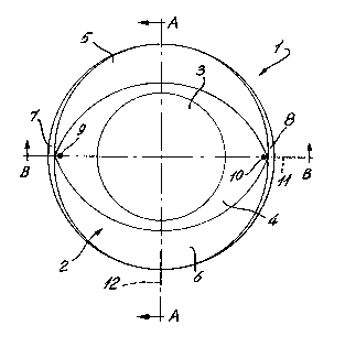
! Figure 1 is a front elevational view of
il a soft toric contact lens in accordance with the
. 25 present invention for astigmatic correction, showing
an anterior surface of this lens;
.,
-~/ Figure 2 is a side elevational, cross
~ sectional view of the contact lens according to the
-~ 30 invention, taken along line A-A of Figure 1 and
¦ showing details of a central optical zone of the
I anterior surface of this lens;
~,1
i,
i
f
. 6
~09~7`9~
Figure 3 is a cross sectional, bottom plan
view of the contact lens according to the invention,
taken along line B-B o~ Figure 1 and showing details
of the central optical zone of the anterior surface of
this lens;
: Figure 4 is a side elevational, cross
. sectional view of the contact lens according to the
- invention, taken along line A-A of Figure 1 and
- 10 showing details of upper and lower peripheral
prismatic zones of the anterior surface of this lens;
Figure 5 is a cross sectional, bottom plan
'l view of the contact lens according to the invention,
` 15 taken along line B-B of Figure 1 and showing details
- of an intermediate aspheric zone of the anterior
surface of this lens;
Figure 6 i5 a cross sectional, bottom plan
view of the contact lens according to the invention,
taken along line B-B of Figure 1 and showing details
of peripheral thinned zones of the anterior surface of
i this lens;
Figure 7 is a rear elevational view of the
soft toric contact lens in accordance with the present
- . invention for the correction of astigmatism, showing
a posterior surface of this lens;
.
Figure 8 is a side elevational, cross
sestional view of the contact lens according to the
invention, taken along line C-C of Figure 7 and
showing details of a central toric zone and an
~'
2 ~ 9 6 7 ~ ~
.
intermediate spherical zone of the posterior surface
of this lens;
Figure 9 is a cross sectional, bottom plan
view of the contact lens according to the invention,
taken along line D-D o~ Figure 7 and showing details
of the central toric zone and intermediate spherical
zone of the posterior surface of this lens;
~ .
.~`; 10 Figure 10 is a cross sectional, bottom
-. plan view of the contact lens according to the
invention, taken along line D-D of Figure 7 and
. showing details of the intermediate spherical zone of
'! the posterior surface of this lens; and
' 15
Figure 11 is an enlarged view of the lower
portion of the contact lens of Figure 8, showing
-' details of a peripheral tangential zone of the
I posterior surface and of a peripheral edge of the
.~20 lens.
, !~
:.1,
~DETAILED DESCRIPTIGN OF THE PREFERRED EMBODIMENT
; 25
,In the specification and the appended
.claims, the term "vertical" and "horizontal" are used
1with reference to the lens as it would be if ideally
seated on the cornea of the eye without any shift in
orientation resulting by movemenk caused by the
eyelid. Regarding the term "rotation", it refers to
rotation of the lens when seated on the cornea of the
eye.
~'
.,
~`
.: ~ . : .. .. ~ ~: :
2Q~7~
:
.,
~ As illustrated in Figure 1, the preferred
: embodiment of the soft toric contact lens 1 in
-:- accordance with the present invention comprises an
, .
- anterior surface 2 formed with a central optical zone
3, an intermediate aspheric zone 4, two upper and
lower peripheral prismatic zones 5 and 6, two
- peripheral thinned zones 7 and 8, and two reference
points 9 and 10. The anterior surface 2 of the lens
, 1 is symmetrical about an horizontal plane of symmetry
containing horizontal axis 11, and about a vertical
: plane of symmetry containing vertical axis 12.
In Figures 1 and 7 of the appended
drawings, while curves appear to delineate distinct
zones of the lens they are shown Eor clarity of
description of the invention only. It will be
; appreciated by those of ordinary skill in the art that
: there are no sharp distinction between these different
zones of the lens, but they are smoothly blended into
20 one another.
,
; Central optical zone 3:
. , .
. The central optical zone 3 i5 the only
zone of the anterior surface that optically corrects
defects of the patient's eye.
: '
The central optical zone 3 is spherical
and, therefore, has a constant radius R (Figure 2).
: 30 The axis of rotation of the central optical æone 3
corresponds to the axis of rotation 21 of the entire
lens 1, whereby this central optical zone 3 is not a
~ : -: : ~ - - ,
: '`
. ~
~ ~ 9 ~
prismatic surface and accordingly does not present the
drawback of producing prismatic aberrations.
;lReferring to Figures 2 and 3, the chord
~l5 C of the central optical zone 3 varies between 7,63
-and 8,80 mm, according to the relation C = 8,8/F, in
which F = D~/15, DT being the diameter of the lens 1.
The central thickness E (Figure 2) may have values
situated between 0,09 and 0,49 mm, depending on the
dioptric power of the lens 1.
, .
,,
~Peripheral prismatic zones 5 and 6:
.,
As indicated in the foregoing description,
rotation of a toric lens l must be prevented to avoid
deviation of the astigmatic correction from the
desired axis. In the lens l according to the
invention, upper and lower peripheral prismatic zones
5 and 6 fulfill this function.
As illustrated in Figure 1, the prismatic
zones 5 and 6 have the general configuration of a
crescent moon and are situated outside the central
optical zone 3. They are also symmetrical about the
horizontal plane of symmetry containing horizontal
axis ll.
The upper prismatic zone 5 is generated,
-~30 as illustrated in Figure 4, by shifting its axis of
rotation 13 vertically and downwardly from the axis of
rotation 21 of the toric lens l by a distance D10.
The radius of curvature R10 of the zone 5 is constant.
; 10
20~7~
In the same manner, the axis of rotation
14 of the lower prismatic zone 6 :is vertically and
upwardly shifted ~rom the lens' axis of rotation 21 by
a distance D20. The radius o-f curvature ~20 of the
zone 6 is again constant.
,
The distances D10 and D20 are identical
but opposite, and can vary between 0,10 and 0,60 mm.
The radius of curvature ~10 and R20 are also identical
; 10 and vary in function of the other parameters of the
lens 1.
As illustrated in Figure 4, the prismatic
zones 5 and 6 define an apex situated along the
peripheral edge 20 (Figure 11) of the lens in the
region of the vertical plane of symmetry containing
axis 12. Also, the lens has, in the region of each
prismatic zone 5, 6, a thickness that gradually
increases from this apex toward the central optical
zone 3.
From the foregoing description, one of
ordinary skill in the art will appreciate that the
; zones 5 and 6 are prismatic and are opposed by their
bases to simulate the conventional thinned zones
discussed in the above brief description of the prior
art. Indeed, due to their prismatic and cre~cent moon
configuration, sliding movement of the wearer's upper
and lower eyelids on the upper and lower prismatic
zones 5 and 6, respectively, will tend to push these
prismatic zones to thereby produce a stabilizing
effect that maintains the contact lens 1 on the
patient's eye in the desired, predetermined angular
-:: : : . : ~,~ -
! ! 2 0 9 6 l O G
i
~orientation corresponding to the orientation of Figure
, .
,:
The advantage of that solution is that the
two prismatic zones 5 and 6 are situated in the
:i.,
periphery of the lens 1 and do not affect the central
optical zone 3 of the lens 1. This enables production
of a lens having a thinner central optical zone 3 free
from prismatic aberrationsO
~'It should also be pointed out here that
,the transmission of oxygen through a contact lens
reduces with the thickness of that lens. Accordingly,
a thinner lens 1 transmits more oxygen to the cornea
and therefore affects its metabolism to a lesser
- extent.
. .,
,Those of ordinary skill in the art know
;ijthat the prismatic aberrations reduce the optical
':,J20 quality and therefore the visual acuity of the
~patient. Accordin~ly, a lens formed with no prism in
1the central optical zone provides the user with a
higher visual acuity.
'.'
Intermediate aspheric zone 4
.
The anterior surface 2 of the lens 1 is
`therefore formed of three main zones: the central
,optical æone 1 and the upper and lower peripheral
;30 prismatic zones 5 and 60 A fourth zone, namely the
intermediate aspheric zone 4 interconnects the central
optical zone 3 and the two peripheral prismatic zones
5 and 6.
. !
~,
"- ' : ` :
~ 12
2~7~
The use of an aspheric intermediate zone
4 flattens the anterior surface 2 of the lens 1; the
aspheric zone 4 enables elimination of the prior art
abrupt junctions between the central optical zone 3
and the intermediate zone 4 which reduces the comfort
of the patient's eye and the stability of the lens
upon blinking movem0nt o~ the upper eyelid. In the
same manner, the aspheric zone 4 eliminates any abrupt
- junction between the intermediate zone 4 and the
peripheral prismatic zones 5 and 6. Therefore, the
aspheric zone 4 forms a smooth transition between the
optical zone 4 and the upper and lower peripheral
prismatic zones 5 and 6.
15More specifically, the surface of the
intermediate aspheric zone 4 is defined by a
progressive elongation of the radius of curvature (Rl
< R2 < ~3 < ~n~ as shown in Figure 5. The transition
j is progressive and invisible whereby the anterior
- 20 surface 2 is smoother and interference of the lens l
with movement of the upper and lower eyelids is, if
not eliminated, substantially reduced.
.
Peripheral thinned zones 7 and ~:
The two peripheral and spherical thinned
zones 7 and 8 (Figures 1 and 6), which are symmetrical
about the vertical plane of symmetry containing
vertical axis 12, improve the comfort of the patient's
eye. Indeed, by making the lens 1 thinner in the
region of the zones 7 and 8, that is at the junction
of the prism, lifting of the upper eyelid upon
blinking movement thereof is reduced whereby
.,
,. . ~ i .
:: .: . :
:i ~
13
~09~70~
,,
..
perturbation of the upper eyelid is also substantially
reduced. Too important a mass at the periphery of the
lens 1 would lift the upper eyelid upon movement
i thereof and, therefore, would affect natural
lubrication of the eye's sclera adjacent a peripheral
thick portion of the contact lens.
.
.:
Reference points 9 and lO:
' 10
- Referring back to Figure 1, the anterior
, surface 2 of the lens 1 is provided with a pair of
diametrically opposed reference points 9 and 10
i situated along the horizontal axis ll. These
reference points enable the practitioner to evaluate
the direction and the amplitude of the rotation (shift
of the axes 11 and 12) of the lens 1 on the eye of the
patient. This will enable fabrication of a contact
j lens whose parameters are chosen to eliminate this
rotation.
-
The lens 1 in accordance with the present
invention further comprises a posterior surface 15
(Figure 7) formed with a central toric zone 16, an
intermediate spherical zone 17, a peripheral
tangential zone 18, and a lens edge 20.
Central toric zone 16:
;; 30
! The c~ntral zone 16 o~ the posterior
surface 15 is toric. More specifically, the central
toric zone 16 comprises a first radius oE curvature
..... .
: \
14
~ .
7 ~ ~
-~ ~30 (Figure 8) corresponding to the minor meridian of
the toric zone 16. It also comprises a second radius
of curvature R40 (Figure 9) corresponding to the ma~or
meridian of the toric zone 16, this major meridian
being orthogonal to the minor meridian and
intersecting the minor meridian at the geometrical
center of the lens. As can be seen, R30 < R40. These
two radii of curvature are determined by the optical
prescription.
,', 10
Chord C30 (Figure 8) of the central toric
zone 16 corresponds to the radius of curvature R30,
-~ while chord C40 (Figure 9) corresponds to the radius
of curvature R40. As can be seen in Figures 8 and 9,
15 C30 < C40. The longer chord C40 has a length varying
between 10,40 and 12,00 mm proportionally to the total
diameter DT of the lens 1, in relation to the above
~, mentioned factor F. The shorter chord C30 varies in
;~ relation to the radius of curvature R30.
In the embodiment illustrated in Figure
~ 7, the major meridian of the toric zone 16 lies on the
- horizontal axis 11 while the minor meridian of the
toric zone 16 lies on the vertical axis 12. However,
it should be kept in mind that, alternatively, the
major and minor meridians may be at an oblique angle
to the axes 11 and 12 depending on the prescription of
the patient.
The central zone 16 is therefore a toric
-~ surface that is responsible for the astigmatic
correction. It also enables a perfect alignment of
:
-
r
~ 15
~9~7~
..
the lens 1 with the surface of the cornea which is
~ also toric.
-1 Intermediate spherical zone 17:
:, ~
: As illustrated in Figure 7, the
intermediate spherical zone 17 surrounds the central
toric zone 16 and interconnects this central toric
. zone 16 and the peripheral tangential zone 1~. This
lO zone 17 is spherical, generated by a single radius of
curvature R50 (Figures 8, 9 and 10). The chord C50 of
the spherical zone 17 which varies between 11,27 and
13,00, proportionally to the total diameter DT of the
lens 1, is given by the relation
C50 = 13 x F
where F = DT/15, as indicated in the foregoing
description.
The radius of curvature R30 and R40 of the
central toric zone 16 are shorter than the radius of
.. curvature R50 of the intermediate spherical zcne 17
and define a toric vault having a deepness PVT varying
between 0,13 and 0,15 mm proportionally to the total
diameter DT of the lens 1, in accordance with the
following relationship:
P~T = 0,15 ~ F
in which ~ = DT/lS.
, . . . , ~ ,
: ,
:
:
~ 16
2~7~
Peripheral tanqential zone 18:
. Referring to Figure 1:l, the peripheral
-` tangential zone 18 is a conical surface defining an
open angle ~ with the prolongation 19 of the
: intermediate spherical zone 17. As the peripheral
zone 18 is tangential to the intermediate spherical
zone 17, no junction exists between these two zones of
the posterior surface 15. The width L (Figure 7) of
the tangential zone 18 varies between 0,87 and 1,00 mm
proportionally to the total diameter D~ of the lens 1,
in relation to the factor F.
The function of the peripheral tangential
zone 18, defining an open angle ~, is to distribute
the pressure of the lens 1 on the sclero-corneal
l limbus, and to prevent (a) pressure indentation oP the
:~, edge 20 (Figure 11) of the lens 1 into the sclera and
(b) perturbation of the circulation in the small blood
vessels of the sclera.
...
; Lens edge 20:
.
, 25 As illustrated in Figure 11, the
peripheral edge 20 of the lens 1 is Pormed with a
rounded profile to reduce to the minimum the
:' interaction between the edges of the upper and lower
.. eyelids with the edge 20 of the lens 1. This improves
both comPort of the patient's eye and stability oP the
contact lens.
.,
~'
:.' ~ : . .: .
:
;~
~ 17
...~
9~7~
.
- Although other materials can be
contemplated, the toric contact lens 1 in accordance
with the present invention is advantageously made of
~ an hydrophillic material with a high content of water
- 5 (at least 55%) in order to ensure comfort of the
patient's eye and a permeability to oxygen sufficient
to respect the corneal metabolism.
.,
The available parameter ranges for the
, 10 lens 1 in accordance with the present invention are
the following~
:
` - Base curves 7,50 to 9,50 mm
- diameters 13,00 to 15,00 mm
- power sphere -20,00 to+20,00 diopters
cylinders-0,75 to-10,00 diopters
axes 0 to 180
-~The above wide ranges of available
~'20 parameters make the lens 1 according to the invention
-a high performance contact toric lens.
,., ~
In the foregoing description, any
numerical value or range is given for the purpose of
exemplification only and should not be interpreted to
limit the scope of the invention.
. .
`~Although the present invention has bean
described hereinabove by way of a preferred embodiment
thereof, this embodiment can be modified at will,
within the scope of the appended claims, without
departing from the spirit and nature of the subject
.
lnventlon .
!
',
~ . .
"., ~ -.