Note : Les descriptions sont présentées dans la langue officielle dans laquelle elles ont été soumises.
A ~ho~ with a Central Fastener
.~
The present invention relates to a shoe with a central fastener
according to the introductory clause of claim 1.
:
Such a shoe is known from DE-U-8 912 788. There, an instep cover
of hard-elastic materi~l is provided over a soft elastic tongue.
Closing flaps that can be moved sideways are hinged to the instep
cover, at the sides, in the area of the foreshoe and each of
these is connected rigidly with a side part of the shoe upper.
The central ~astener is attached rigidly to the instep cover,
which is to say is connected i~separably with this. At least one
rope-like tightening element runs from th~ central fastener
alternately over guide elements of the closing flaps and of the
instep cover. The central fastener, instep cover, and closing
~laps form a technical unit that can be prefabricated and checked
prior to use/ and which functions in a reliable manner.
DE-A-2 341 658 describes a sXi boot with a central fastener and a
tongue-like middle upper which, ~or purposes of easier access is
connect-d to the foreshoe in the manner of a hlnge at the toe.
.~
'
,
- 2 ~
The central ~aste~er is provided on the middle upp~r in the form
of a rotatable toggle. A tightening rope runs both upward and
downwards from this central fastening device, essentially
transversely ko the middle upper. This tightening rope forms a
loop on the outside and after a transverse return through the
middle upper and after formation o~ another loop on the other
side of the middle upper at the same height as the first loop, it
is fastened to the middle upper. The loops, which are opposite
each other, are located in the area of the bend of the foot at
the end of the instep, i.e., in the joint at the transition to
the lower leg. Two other loops are provided in the area of the
ball of the big toe or of the metatarsophalangeal joints. Hooks
are formed on the upper material of the ski boot. When the
middle upper is folded against the upper, the loops are placed
over the hooks and, by rotation of the toggle, the tightening
rope is put under tension by a rope roller that is connected to
the toggle, so that khe ski boot is tightly closed. When this is
done, in each instance tension acts perpendicularly to~the
extension of the middle upper which, in each instance, covers the
side uppers. With such a~configuration, good access to the ski
boot is indeed possible although positioning loops over the hooks
when closing the ~oot is bothersome and time-consuming and is a
problem especially when the hooks are clogged with snow or ice.
.,
Using the present invention it is intended to solve the problem
of so improviny a boot with a central fastener of the type
described in the introduction hereto that the central fastener
can be replaced in a simple manner--as in the case of laces in a
conventional shoe--when a good adaptation of the shoe to the foot
is made possible, particularly in the upper area, so that despite
.
.'~
.
- ~a ~ 7 ~J
good fixing of the foot in the shoe, the mobility of the foot in
the area of the metatarsophalangeal joints as well as in the area
of the upper and lower ankle joint is not restricted.
This problem has ~een solved by the features set out in patent
claim 1. ~ecause of the configuration according to the present
invention, the shoe remains flexible in the area of the
metatarsophalangeal joints and the tongue, especially
its center part, as a result of the soft elastic design
can fit well over the entire instep length on the
instep formj i.e., on the instep arch of the foot.
Since the holding plate for th~ central fastener does
not completely cover the instep length but a lower
partial area of the tongue remains free and thus
elastic, for the shoes, which are not alpine ski boots,
important mobility of the foot in the area of the
metatarsophalangeal ~oints is assured. This applies
bec~use of the dimensioning of the length of the
holding plate also for the unhindered mobility of the
upper and lower ankle joint, which in shoes of the type
according to the invention -- also in contrast with
alpine ski boots -- is not impaired and does not have
to be completely eliminated at all.
- 3 -
By instep length is meant -- according to the
lower illustration of fig.l -- the distance between the
upper and lower ankle joint and the metatarsophalangeal
joints.
Other advantageous details of the invention are
indicated in ~he subclaims and are described helow in
greater detail by the embodiments illustrated in the
drawing. There are shown in:
Fig. 1, a perspective exploded view of different
individual elements of a shoe and the related central
fastener,
Fig. la, the view oi a part of the central
fastener seen in the direction of arrow I of fig. 1,
Fig. 2, a top view of the shoe composed of the
individual parts of fig. 1,
Fig. 3, a part of the side view of the shoe of
fig. 2/
Fig. 4, the view of straps used with a tension
strip before assembly,
Fig. 5, a section through the tension strip of
section plane II II of fig. 4 and
Fi~. 6, a partial view of the tension strip and
the related headpiece of a strap.
In fig. 1 a shoe 1 according to the invention is
represented in exploded view in its essential
individual elements. Here it is preferably a sport,
leisure or rehabilitation shoe, i.e., a shoe, whose
upper in contrast with an alpine ski boo~, does consist
of dimensionally stable shell-shaped upper parts but
whose upper consists of a uniform, deformable upper
material or of several deformable upper materials such
as leather, artificial leather, fiber fabric,
optionally provided with leather or artificial leather
trimmings. These sport or leisure shoes include, for
example, training shoes, tennis shoes, jogging shoes or
also special sport shoes such as running shoes, jumping
shoes or the like.
By rehabilitation whoes or shoes for
rehabilitation purposes are meant especially those
- 4 -
shoes which make i~ possible in $he case of psrsons
wi~h foot injuries or who have had foot operations for
the rigid holding devices, such as plaster casts,
orthotic devices or the like, to be able to be removed
as soon as possible again and for the patient to be
able as ~uickly as po6sible to walk again, without
renewed injuries or secondary injuries occurring, for
example, by false walking positions because of the so-
called "relieving postures." Such rehabilitation shoes
are described in greater detail in DE-A-3S 20 786.
Shoe 1 represented in exploded view according to
fig. 1 consists of a sole (not indicated in greater
detail), the upp~r material with side parts 3 and 4 of
upper 2, heel part 5, foreshoe 6 and an insole 7.
Edge 8 of side parts 3, 4 ending in the instep
area is provided with a stiffening element 9, 10 each
in the form of
tension strip 9.1 or 10.1 consisting of an elastic~
flexi~ly deformable material. Each of tension strips
9.1 or 10.1 is provided with two longitudinal slots 11
or 12 each. Below longitudinal slots 11, 12 a strap
13, 14 each come~ out which each run over side parts 3
or 4 of upper 2 in the sole area and are fastened
between the upper material and the sole material.
A well cushioning tongue 15 of soft elastic
material, preferably of foamed plastic, is inserted
into the shoe opening in the instep area and with end
17, turned toward toe 16, is shoved under the upper
material and is deflectably fastened there by stitching
and optionally gluing. Side walls 18, 19 of tong~e 15
thus come to lie below side parts 3, 4 of upper 2. By
the removal of tension strips 9.1, 10.1 or by
dimensioning of th~ height of edges 8 of side parts 3,
4 of upper 2 an opening 20 is formed which leaves a
center strip 21 of tongue 15 free even in maximum
closing position in a width of at least 1.5 to 2 cm.
In tongue 1~ preferably in its center third on its
upper surface a shallow depression 22 is provided, in
which a holding plate 23 of a central fastener 24 is
~ 5 ~ ?~J ~
inserted and can be fastened there, for example, by
; gluing, stitching or sheathing. Holding plate 23
consists of a hard elastic dimensionally stable and
thus hardly or only slightly deformable material,
especially of a hard compact plastic such as polyamide,
p~lyimide, polyethylene or the like. Length 25 of
holding plate 23 and its arrangement on center strip 21
of tongue 15 is ~elected 80 that about 25~to 95% of
inst~p length 26 can be covered, but at least 5%,
preferably 20% to 50~, of .instep length 26 between
front edge 27 of holding plate 23 and fastened end 17
remains free and therefore flexible and moreover
according to a preferred embodiment at least about 10%
.:: of instep length 26 behind back edge 28 of holding
plate 23 remains free or is covered only by tongue 15
wi~h a tongue part 29 extended in the direction to the
upper and lower ankle jointO
;. Holding plate 23 is provide with a support 30 in
.. ~ the form of a deepened base plate and with tab sections
31, 32 annularly surrounding it. A closing part 33 can
be inserted into this support 30 and, for example, can
be fastened there by gluing.
Closing part 33 comprises a solid lower part 34
with lateral arms 35,36 and a ro~atable adjustment
button 37. Between lower part 34 and adjustment button
: 37 is provided a winding device with locking action and
optionally with an unlocking possible by pressure on
button 38 for a tightening element 3g or for the two
ends of a one-piece tightening element or for the ends
~ of two tightening element sections. By rota~ion of
. adjustment button 37 in one direction tightening
element 39 i8 wound up and by rotation in the opposite
direction -- as is known -- it is unwound.
With the insertion of closing part 33l arms 35, 36
laterally engage over holding plate 23~ A recess 40
for guiding tightening element 39 is/are provided in
arms 35, 36 and/or in the suppor~ 30 locat~d under
them.
- 6 ~ S~ ~
A catch lug 41 each is formed on lower part 34 on
the front side and rear side (not visible). With
insertion of closing part 33 the lug engages tab
sections 31 or 32 thr~ugh an opening 42 each of support
30 so that closing part 33 can be fastened to holding
plate 23 by a catch connection. Holding plate 23 has
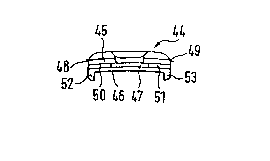
an 0xtension 43 projecting forward. ~he extension
itself or an attachment 44 -- represented in fig. la in
the view of arrow I --can be superpo~ed on it and/or
locked with it and/or glued to it and/or welded by an
ultrasonic welding connection, is d0signed double-
shelled. Between upper shell 45 and lower shell 46 a
space 47 ~ith an inside width iæ provided, which is the
same or somewhat greater than the thickness of
tightening element 39.
The two shells 45, 46 are connected to one another on
sides 48, 49 by guide elements 50, Sl for tightening
element 39 provided or f~rmed on in space 47.
Pref~rably extension 43 and/or attachment 44 in each
case designed as one piece, are produced, for example
by injection or die-casting molding process.
Attachment 44 can be pro~ided on sides 48,49 with one
fixing tab 52,53 each projecting downward.
In assembly, tightening element 39 i~ shoved
forward from the rear through space 47 of attachment
44, and upper and lower lateral loops are formed, which
are brought into working connection with guide elements
of side parts 3, 4, as is illnstrated below by fig. 2.
Fig.2 shows in top view a shoe 1 assembled rom
the individual parts of fig. 1. Tongue 15, matched in
cross section approximately to the curvature of the
instep of a food covers at least about 60% of the
instep area visible from above with its si.de walls 18,
19. At the same time, the surface of side walls 18, 19
i5 designed as a sliding surface for adjacent side
parts 3, 4.
According to a feature of the invention,
tightening element sections 54, 55 guided in the top,
i.e., in the guide groove ~- lying closest to the heel
. 7 ~
-- of holding plate 23 and/or of recess 40 of arms 35,
36 on lower part 34 of closing part 33 starting from
adjustment button 37 ~f central fastener 24, first are
: guided back over guide elements 56, 57, which are in
nonpositive connection with side parts 3,4, to guide
elements 50, 51 of holding plate 23 and from it to the
front guide elements 58, 59 and finally from them to
the f.ront part of center strip 21 of tongue 15. In a
one-piece tightening element 39 returning section 60
; lies in a crosswise groove 61 of center strip 21 of
tongue 15. Additionally, a pipe section 62 can be
shoved over it there. ~lso section 60 in crosswise
groove 61 can be secured against lateral shifting.
Although in the embodiment according to fig. 2
only two guide elements are provided in each side part
3 or 4, it is basically conceivable to place other
guide elements there, which would be corresponding
;` brought into working connection with other guide
elements on holding plate 23. Also it is basically
possible, to config-lre the qlliding of tightening
: element 39 so that, for example, tightening element
sections 63, 64 or 65, 66 cross one another in the area
. of`holding plate 23 under central fastener 24.
With a tightening element 39, consisting of two
tightening element sections, the ends are fastened
either in the area of crosswise groove 61 on tongue 15
. or on side parts 3, 4.
As can be seen in fig. 2, at least the two top
lateral tightening element sections 54, 55 of
tightening element 39, but preferably also directly
following tightening elemen~ sections 63, 64 are
proYided to run from their guides on holding plate 23
or from center strip 21 of ~ongue 15 obliquely b~ckward
to the respective guide elements 56, 57 or 58, 59
provided there. In this way, the tensile stress,
occurring in the top or in the two top tightening
:: element sections 54, 55 or 63, 64 in olosing is guided
: in the direction of heel part 5. In this case, straps
. 13, 14 preferably are also a.rranged so that the tensile
. ' .
- 8 ~ 7 ~ ~ ~
stress, on the one hand, runs directed downward to the
sole and, on the other hand, backward ~o heel 5.
The other tightening element sections 65, 66 or 60
preferably run from holding plate 23 or from center
stxip 21 of tongue 15, in top view, obliquely forward
or crosswise to tongue 15.
~ o guarantee an effecti~e insertion of the tensile
stress in straps 13, 14, the respective guide elements
56, 57 and 58, 59 are applied, preferably are fcrmed
on, headpiece 67 each of a strap 13, 14, as illustrated
by fig. 4 to ~. Headpiece 67 is put into a lower
insertion slot 68 each of tension strip 10.1 opposite
longitudinal slot 10 or 11 and locked by a catch 60
with lower edge 70 of insertion slot 68.
Behind slots 11,12 for inserkion of strap 39 is
placed a stop 71, for example in the form of a tab, on
which front edge 72 of headpiece 67 can strike after
bridging a certain clearance of a few millimeters.
On upper surface 73 of guide elements 56, 57 or
58, S9 is provided an edge 75 projecting over its
peripheral area 74. Groove 76, thus formed, for
tightening element 39 runs flush in a plane with slots
ll or 1~. Projecting edge 75 on the side opposite
front edge 72 of headpiece 67 is separated by a slit 77
for insertion of tightening element 39 from th~
remaining material of strap 13 or 14.
Tension strips 9.1, 10.1 are advantageously
provided with a formed-on fastening tab 78 each. With
these fastening tabs 78 they can be stitched and/or
glued and/or riveted to the upper material. Fastening
tabs 78 preferably are formed on so that they run in a
plane below slots 11, 12 or insertion slot 68 and their
su~rface is flush with lower edge 70 of insertion slot
68.
Tongue 15 advantageously consists of a foamed
polymer, preferably of a thermoplastic, pressure-
transmitting cushioning material in the form of foamed
polyethylene, polyurethane or ethylene vinyl acetate.
Tongue 15 can be provided on its underside with a
textile lining 79, a~ fig. 2 and 3 show~ In the sarne
-` way, the upper surface of tongue 15 can also be cov~red
at least partially with a textile layer, with leather
or other usual shoe materials, especially it can be
lined with it.
Stiffening elements 9, lO or tension strips 9.l,
lO.l preferably consist of elastic plastics, especially
polyamide, polyimide, polyurethane or the like. This
also applies to straps 13, 14, which preferably consist
of said plastics in transparent embodiment so that the
trademark m~rkin~s of the shoes under discussion cannot
become invisible.
By variant embodiment of the invention represented
in fig. l to 6, in which a mechanical connection of
stiffening elements 9, lO or of tension strips 9.l,
i lO.l with straps 13, 14, and by them with the upper
and/or sole material, is produced, a width regulating
system is obtained, with which the inside dimensions of
the shoe upper can be exactly matched to the peripheral
measurement of the foot. In this case, central
fastener 24 performs a multiple function. It serves
not only for production of a uniform ad~ustable closing
pressure uniformly distribu~ed over the entire shoe but
also at the same time it causes an increased stability
of the complete shoe in the sense that the danyer of
straining of the sensitive joints and tendons,
preferably in the shoe outside area, it reduced to ~he
greatest possible extent.
It is especially advantageous that above-described
central fastener 33 together with tigh~ening element 39
basically can be detached from holding plate 23 and in
practice can be replaced like a shoe lace. As a result
central fastener 33 with tightening element 39 can be
completed as a partial element of the shoe according to
the invention and be tested for serviceabilityO Still
central fastener 33 with tightening element 39 can also
be replaced after assembl7 of shoe l -- like a ki~
system. As a result the error rate or rejection ratio
- 10 ~ 76~
is considerably raduced, ~hich for a "High-Tec" shoe of
this type is especially important.
Soft elastic tongue 15, provided as instep cover,
forms a pressure damping intermediate member between
comparatively rigid holding plate 23, acted on by the
tension forces, and the shoe wearer's foot. Holding
plate 23 consists of a hard, dimensionally stable
material, which preferably has a Shor~ hardness of 60
to 80 Shore D. Consequen~ly, holding plate 23, on the
one hand, acts as a pressure distribution element
without, on the other hand, the deflectability of
tongue 15 being made difficult at tongue end 17.
Tongue 15 consists of essentially softer material than
holding plate ~3, thus i~ has a Shoræ hardness clearly
below 60 Shore D.