Sélection de la langue

Search

Sommaire du brevet 2097455 

Énoncé de désistement de responsabilité concernant l'information provenant de tiers

Une partie des informations de ce site Web a été fournie par des sources externes. Le gouvernement du Canada n'assume aucune responsabilité concernant la précision, l'actualité ou la fiabilité des informations fournies par les sources externes. Les utilisateurs qui désirent employer cette information devraient consulter directement la source des informations. Le contenu fourni par les sources externes n'est pas assujetti aux exigences sur les langues officielles, la protection des renseignements personnels et l'accessibilité.

Disponibilité de l'Abrégé et des Revendications

L'apparition de différences dans le texte et l'image des Revendications et de l'Abrégé dépend du moment auquel le document est publié. Les textes des Revendications et de l'Abrégé sont affichés :

  • lorsque la demande peut être examinée par le public;
  • lorsque le brevet est émis (délivrance).
(12) Brevet: (11) CA 2097455
(54) Titre français: GROUPE DE DEUX PORTES COUPE-FEU POUR UN ASCENSEUR
(54) Titre anglais: BANK OF TWO FIRE DOORS FOR AN ELEVATOR
Statut: Périmé et au-delà du délai pour l’annulation
Données bibliographiques
(51) Classification internationale des brevets (CIB):
  • B66B 13/30 (2006.01)
(72) Inventeurs :
  • HOEFSLOOT, LEON (Belgique)
(73) Titulaires :
  • KONE CORPORATION
(71) Demandeurs :
  • KONE CORPORATION (Finlande)
(74) Agent: G. RONALD BELL & ASSOCIATES
(74) Co-agent:
(45) Délivré: 1997-03-04
(22) Date de dépôt: 1993-06-01
(41) Mise à la disponibilité du public: 1993-12-05
Requête d'examen: 1993-06-23
Licence disponible: S.O.
Cédé au domaine public: S.O.
(25) Langue des documents déposés: Anglais

Traité de coopération en matière de brevets (PCT): Non

(30) Données de priorité de la demande:
Numéro de la demande Pays / territoire Date
922585 (Finlande) 1992-06-04

Abrégés

Abrégé anglais


A fire door is adapted to be fitted to a landing
doorway of an elevator shaft so as to extend abreast of a
landing door of the elevator. Previously such a fire door was
constructed sufficiently thick that it per se satisfied fire
protection regulations; this resulted in a heavy fire door with
a correspondingly heavy support structure. However, the fire
protection characteristics of the fire door of the invention are
so chosen that, when the landing door and the fire door are
abreast of each other, their combined fire protection
characteristics satisfy fire protection requirements imposed on
a fire door by the applicable fire regulations.

Revendications

Note : Les revendications sont présentées dans la langue officielle dans laquelle elles ont été soumises.


6
THE EMBODIMENTS OF THE INVENTION IN WHICH AN EXCLUSIVE
PROPERTY OR PRIVILEGE IS CLAIMED ARE DEFINED AS FOLLOWS:
1. A fire door arrangement for an elevator,
especially for use in landing doorways of an elevator shaft,
comprising:
a fire door mounted abreast of an elevator landing
door with means for moving the fire door and the
elevator landing door relative to each other;
the fire door having a first fire protection charac-
teristic and the elevator landing door having a
second fire protection characteristic, the fire
protection characteristic of the elevator landing
door being effective together with the fire
protection characteristic of the fire door to
fulfill a total fire protection characteristic of
the fire door arrangement; and
wherein the fire door is placed between the elevator
landing door and a wall of an elevator shaft.
2. The fire door arrangement according to claim 1,
further including a roller race for the fire door and a
roller race for the elevator landing door, the roller races
being attached to the same supporting element.
3. The fire door arrangement according to claim 2,
wherein the roller races are mounted relative to each other
so that the roller race of the fire door is located higher
up than the roller race of the elevator landing door.
4. The fire door arrangement according to either
claim 1 or claim 2, further including means separate from
the elevator landing door for automatically closing the fire
door.
5. The fire door arrangement according to claim 2,
wherein the roller race of the fire door is mounted in a

7
slanting position so that the fire door is closed by the
force of gravitation.
6. The fire door arrangement according to claim 1,
further including means separate from the elevator landing
door for closing the fire door by force.
7, The fire door arrangement according to claim 2,
wherein the supporting element is a plate arranged in a
vertical direction; and
the roller race of the fire door and the roller race
of the elevator landing door are mounted on
opposite sides of the plate.
8. The fire door arrangement according to claim 1,
wherein the fire door includes two leaves and the elevator
landing door includes two leaves; and
a first leaf of the fire door includes a first means
for interacting with a second means on the second
leaf of the fire door for joining the leaves.
9. The fire door arrangement according to claim 8,
wherein the means forms a joint.

Description

Note : Les descriptions sont présentées dans la langue officielle dans laquelle elles ont été soumises.

- 2097~55
The present invention relates to an elevator fire
door, and in particular, to a fire door mounted in a doorway
of an elevator shaft.
Fire doors are normally used in the landing doorways
of an elevator shaft to prevent the propagation of fire and
thermal radiation, and to restrict the flow of combustion
gases from floor to floor through the elevator shaft during
a fire. Most countries have enacted laws or regulations which
impose specific performance requirements (i.e. heat
resistance, thermal insulation value, fire penetration,
blockage of combustion gases etc.) which must be fulfilled by
a fire door.
Fire door installations are known in which every (or
almost every) floor is provided with a separate fire door in
addition to the landing door of the elevator shaft. In these
installations, the fire door is a completely separate
structure from the landing door of the elevator shaft, which
means that it occupies a large space and is eY~encive.
There are also known installations in which the
landing door of the elevator shaft also functions as a fire
door. A fire door of this type is described in DE publication
3803317. In these cases, the door is of a very thick and
massive structure. Due to the large mass of the door, it is
slow in operation. Furthermore, when the elevator is out of
order, the lA~Aing door may remain open, in which case it
provides no fire protection at all.
A primary object of the present invention is to
provide a completely new type of fire door for elevator
shafts.
According to an aspect of the present invention,
there is provided a fire door for use in the landing doorways
of an elevator shaft, wherein the fire door is mounted abreast
of the landing door or equivalent of the elevator and the fire
protection characteristics of the fire door are so chosen that
the landing door and the fire door together fulfil the
requirements imposed on a fire door.

20974S5
-
The invention is based on the idea that, on every
(or almost every floor) the landing doorway of the elevator
shaft is provided with two parallel pairs of door leaves
mounted on the same supporting element so that, as seen from
the elevator shaft, the inner doors are normal landing doors
of the elevator while the outer doors only function in a fire
situation. The two doors cooperate together to fulfil the
performance requirements imposed on a fire door by the
applicable laws and regulations.
As compared with conventional fire doors, the fire
door of the invention has several advantages. Firstly, the
doors are arranged in a single door structure, which takes up
less space than a conventional structure in which, in addition
to the lAn~ing door of the elevator shaft, there is a separate
door that alone meets the requirements placed on a fire door.
It is also easier to install. In case of malfunction, when
the landing doors of the elevator are open, the fire door can
be closed independently of the lAn~ing doors. In this way,
the performance requirements of the fire door are fulfilled,
although for a shorter time. The arrangement according to the
invention is safer because the movable door mass in normal
elevator operation is smaller than when a massive landing door
is used as a fire door. Finally, the elevator also provides
faster service than in the case of heavy doors, because light-
weight doors can be moved faster.
Embodiments of the invention will now be describedby way of example with reference to the accompanying drawings
in which:
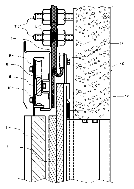
Figure 1 shows a partially sectioned lateral view
of the upper part of the fire door of the invention; and
Figure 2 shows a simplified cross-sectional top view
of the fire door of the invention.
In the emho~iment of Figure 1, the fire door of the
invention is illustrated in a partly sectioned side view. The
fire door structure consists of the normal landing door 1 of
the elevator and a fire door 3 mounted abreast of it. In the

~ 209745~
embodiment presented in Figure 1, the fire door is placed
between the 1An~; ng door 1 and the wall 2 of the elevator
shaft. This arrangement æimplifies the door structure and
allows easier placement of the operating mechAnism of the
landing door. Note that in Figure 1, the elevator shaft is
to the left of the doors while the landing is to the right.
The fire protection characteristics of the fire door 3,
especially its thickness and/or insulating material, are so
selected that the landing door 1 and the fire door 3 together
fulfil the requirements imposed on a fire door.
The landing door 1 and the fire door 3 of the
elevator are mounted on rails 5, 6 or the like attached to a
supporting element 4. The supporting element 4 is most
suitably anchored in the wall 2 of the elevator shaft by means
of mounting elements 7, 8. The supporting element 4 is
preferably a plate arranged in a substantially vertical
position and provided with a landing door roller race 5 or the
like attached to one side of it and a fire door roller race
6 or the like attached to the other side. The roller races
5, 6 are so mounted relative to each other that the fire door
roller race 6 is higher up while the landing door roller race
5 is lower down. This door supporter structure makes it
possible to use a thinner structure than in previous fire
doors. Noreover, an overlapping supporter mechAn;sm can be
used and the door mechAnism can thus be better protected. The
upper edge of the fire door 3 protects the door mechAnicm.
Thus, the door has a better ability to function after a fire
situation. The doors in the figure are horizontally movable
sliding doors opening at the middle. The landing door 1 is
preferably arranged to move on the roller race 5 by means of
roller elements 9, 10 provided at the upper part of the door.
The landing doors 1 of the elevator are actuated by means of
a known apparatus (not shown). The fire door 3 is arranged
to move on the roller race 6 by means of one or more roller
elements 11 provided at the upper part of the door.

2097455
Figure 1 shows the suspension of only the upper
parts of the doors. The lower parts of the doors are arranged
to move e.g. by means of a guiding element in a groove which
is preferably parallel to the corresponding roller race S, 6.
5In a normal situation, the fire door 3 is open, the
leaves 3a, 3b being locked in place e.g. by means of a latch
(not shown in the figure). The latch is so arranged that it
will release the door leaves in the event of a fire. One
possibility is to connect the latches to a fire alarm
10apparatus so that they will operate in accordance with control
commands received from the latter. Another advantageous
application is to make the latch from a meltable material, in
which case the door locking will be released when the
temperature rises to a predetermined value. US Patent
153,598,202 proposes various solutions for the control of an
elevator door latch. The fire door 3 has an arrangement for
automatic closing. In a preferred emho~iment, the roller race
6 of the fire door 3 is mounted in a slanting position so that
the door leaves 3a, 3b will naturally move towards the middle
20of the doorway, closing the fire door under the influence of
gravity. In another preferred embodiment, the door leaves 3a,
3b are arranged to be closed by means of an actuating
merhAnicm based on the use of a counterweight. In this case,
when the latch releases the locking of the fire door, the
25counterweight causes the door leaves to close.
The fire door has an arrangement whereby the
junction between the two door leaves 3a, 3b is sealed in a
fire situation. In the example illustrated by Figure 2, door
leaf 3a is provided with a male type joining element and the
30other door leaf 3b with a female type joining element. The
joining elements of the door leaves fit into each other when
the door is closed, thus sealing the juncture between the door
leaves 3a, 3b.
The doorway is preferably ~LLounded by sealings 12
35which are so arranged that they will eYrAn~ in a fire
situation, preventing propagation of fire into the elevator

20974~5
-
shaft or equivalent through the space between the fire door
3 and the wall 2 of the elevator shaft.
The fire door of the invention can have a thinner
structure than in previously known solutions. In itself, the
door is a typical fire door with insulating material between
its face plates.
It will be obvious to a person skilled in the art
that the invention is not restricted to the examples described
above, but that it may instead be varied within the scope of
the following claims.

Dessin représentatif
Une figure unique qui représente un dessin illustrant l'invention.
États administratifs

2024-08-01 : Dans le cadre de la transition vers les Brevets de nouvelle génération (BNG), la base de données sur les brevets canadiens (BDBC) contient désormais un Historique d'événement plus détaillé, qui reproduit le Journal des événements de notre nouvelle solution interne.

Veuillez noter que les événements débutant par « Inactive : » se réfèrent à des événements qui ne sont plus utilisés dans notre nouvelle solution interne.

Pour une meilleure compréhension de l'état de la demande ou brevet qui figure sur cette page, la rubrique Mise en garde , et les descriptions de Brevet , Historique d'événement , Taxes périodiques et Historique des paiements devraient être consultées.

Historique d'événement

Description Date
Le délai pour l'annulation est expiré 2009-06-01
Lettre envoyée 2008-06-02
Lettre envoyée 2003-04-01
Accordé par délivrance 1997-03-04
Demande publiée (accessible au public) 1993-12-05
Toutes les exigences pour l'examen - jugée conforme 1993-06-23
Exigences pour une requête d'examen - jugée conforme 1993-06-23

Historique d'abandonnement

Il n'y a pas d'historique d'abandonnement

Historique des taxes

Type de taxes Anniversaire Échéance Date payée
TM (brevet, 5e anniv.) - générale 1998-06-01 1998-05-11
TM (brevet, 6e anniv.) - générale 1999-06-01 1999-05-12
TM (brevet, 7e anniv.) - générale 2000-06-01 2000-05-15
TM (brevet, 8e anniv.) - générale 2001-06-01 2001-05-16
TM (brevet, 9e anniv.) - générale 2002-06-03 2002-05-15
Enregistrement d'un document 2003-02-28
TM (brevet, 10e anniv.) - générale 2003-06-02 2003-05-14
TM (brevet, 11e anniv.) - générale 2004-06-01 2004-05-17
TM (brevet, 12e anniv.) - générale 2005-06-01 2005-05-16
TM (brevet, 13e anniv.) - générale 2006-06-01 2006-05-15
TM (brevet, 14e anniv.) - générale 2007-06-01 2007-05-17
Titulaires au dossier

Les titulaires actuels et antérieures au dossier sont affichés en ordre alphabétique.

Titulaires actuels au dossier
KONE CORPORATION
Titulaires antérieures au dossier
LEON HOEFSLOOT
Les propriétaires antérieurs qui ne figurent pas dans la liste des « Propriétaires au dossier » apparaîtront dans d'autres documents au dossier.
Documents

Pour visionner les fichiers sélectionnés, entrer le code reCAPTCHA :


Pour visualiser une image, cliquer sur un lien dans la colonne description du document. Pour télécharger l'image (les images), cliquer l'une ou plusieurs cases à cocher dans la première colonne et ensuite cliquer sur le bouton "Télécharger sélection en format PDF (archive Zip)" ou le bouton "Télécharger sélection (en un fichier PDF fusionné)".

Liste des documents de brevet publiés et non publiés sur la BDBC .

Si vous avez des difficultés à accéder au contenu, veuillez communiquer avec le Centre de services à la clientèle au 1-866-997-1936, ou envoyer un courriel au Centre de service à la clientèle de l'OPIC.


Description du
Document 
Date
(aaaa-mm-jj) 
Nombre de pages   Taille de l'image (Ko) 
Revendications 1994-03-04 2 54
Dessins 1994-03-04 2 58
Description 1994-03-04 5 200
Abrégé 1997-02-24 1 20
Description 1997-02-24 5 223
Revendications 1997-02-24 2 66
Dessins 1997-02-24 2 63
Abrégé 1994-03-04 1 11
Dessin représentatif 1999-04-05 1 34
Avis concernant la taxe de maintien 2008-07-13 1 171
Taxes 1997-04-24 1 41
Taxes 1996-05-29 1 32
Taxes 1995-05-28 1 34
Correspondance de la poursuite 1993-06-22 1 40
Correspondance reliée au PCT 1996-12-16 1 33
Correspondance de la poursuite 1995-11-13 2 80
Demande de l'examinateur 1996-01-04 2 67
Correspondance de la poursuite 1996-03-12 2 52
Demande de l'examinateur 1995-05-15 2 81