Sélection de la langue

Search

Sommaire du brevet 2098249 

Énoncé de désistement de responsabilité concernant l'information provenant de tiers

Une partie des informations de ce site Web a été fournie par des sources externes. Le gouvernement du Canada n'assume aucune responsabilité concernant la précision, l'actualité ou la fiabilité des informations fournies par les sources externes. Les utilisateurs qui désirent employer cette information devraient consulter directement la source des informations. Le contenu fourni par les sources externes n'est pas assujetti aux exigences sur les langues officielles, la protection des renseignements personnels et l'accessibilité.

Disponibilité de l'Abrégé et des Revendications

L'apparition de différences dans le texte et l'image des Revendications et de l'Abrégé dépend du moment auquel le document est publié. Les textes des Revendications et de l'Abrégé sont affichés :

  • lorsque la demande peut être examinée par le public;
  • lorsque le brevet est émis (délivrance).
(12) Demande de brevet: (11) CA 2098249
(54) Titre français: BOUCLES DE BOTTE DE SKI MUNIES D'UN DISPOSITIF D'AJUSTEMENT DE LA TENSION
(54) Titre anglais: SKI-BOOT FASTENING WITH A DEVICE FOR ADJUSTING THE FASTENING TENSION
Statut: Réputée abandonnée et au-delà du délai pour le rétablissement - en attente de la réponse à l’avis de communication rejetée
Données bibliographiques
(51) Classification internationale des brevets (CIB):
  • A43B 05/04 (2006.01)
  • A43C 11/14 (2006.01)
(72) Inventeurs :
  • NICOLETTI, GRAZIANO (Italie)
(73) Titulaires :
  • CANSTAR ITALIA S.P.A.
(71) Demandeurs :
  • CANSTAR ITALIA S.P.A. (Italie)
(74) Agent: OYEN WIGGS GREEN & MUTALA LLP
(74) Co-agent:
(45) Délivré:
(22) Date de dépôt: 1993-06-11
(41) Mise à la disponibilité du public: 1994-02-14
Licence disponible: S.O.
Cédé au domaine public: S.O.
(25) Langue des documents déposés: Anglais

Traité de coopération en matière de brevets (PCT): Non

(30) Données de priorité de la demande:
Numéro de la demande Pays / territoire Date
MI 92 U 000785 (Italie) 1992-08-13

Abrégés

Abrégé anglais


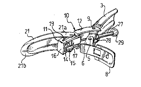
"A ski-boot fastening with a device for adjusting the
fastening tension"
ABSTRACT
The ski-boot fastening described has a device for
adjusting the fastening tension, in which a slide (17)
operated by male-and-female screw means (25, 26)
supports the pin (18) which connects the engagement
element (4) to the tensioning lever (3) of the
fastening.

Revendications

Note : Les revendications sont présentées dans la langue officielle dans laquelle elles ont été soumises.


6
CLAIMS
1. A fastening for sports footwear, particularly for
ski boots and the like, comprising a tensioning lever
(3) pivotable on a support base (8), and an engagement
element (21) which has an operative end (21b) and the
other end (21a) of which is mounted pivotably on a pin
(18) associated with a tension element (10) hinged on
the lever (3) and extending substantially in alignment
therewith, characterised in that the pin (18) is
supported by a slide which is movable along guides (19,
20) extending longitudinally in the tension element
(10), means (25, 26) substantially of the
male-and-female screw type being associated with the
lever (3) for moving the slide (17) in the guides (19,
20).
2. A fastening according to Claim 1, characterised in
that the tension element (10) has a substantially
box-like structure with facing long walls (14, 15)
extending longitudinally thereof, the walls (14, 15)
having the guides (19, 20) for the slide (17).
3. A fastening according to Claim 2, characterised in
that the guides are constituted by slots (19, 20) in
the walls (14, 15) of the tension element (10),
portions of the pin (18) projecting from the opposite
sides of the slide (17) and being slidably engaged in
the slots (19, 20).
4. A fastening according to Claim 1, characterised in
that the screw (25) of the essentially male-and-female
screw-type means (25, 26) is connected directly to the
slide (17) by means of a cable (24) having opposite
ends fixed to or inset in the slide (17) and the screw

(25), respectively.

Description

Note : Les descriptions sont présentées dans la langue officielle dans laquelle elles ont été soumises.


2~
DESCRIPTION
From a general point of view, the present invention
relates to a fastening for sports footwear such as, for
example, ski-boots and the like, and comprises a lever
for tensioning a generally ring-shaped engagement
element articulated thereto. In most cases, in order
to achieve this articulation, the opposite end of the
engagement element to its operative or functional end
is articulated to the tensioning lever with an
articulation axis parallel to the pivot axis of the
lever itself.
As is well known, in order to fasten, for example, a
ski boot, the operative end of the engagement element
is engaged, with the lever open, in one of a plurality
of corresponding engagement means, generally
constituted ~y three or more sawtooth-like projections
fixed to or otherwise formed on a support base, and the
lever is then closed, tensioning the engagement
element. In this case, the variability of the
fastening tension is linked closely to the number,
which is always moderate, of corresponding engagement
means and to the spacing the~eof.
In order to satisfy a widespread need for improved
adjustability of the fastening tension to the needs of
an individual user, the tensioning levers have for some
time had adjustment devices, by means of which ~t is
possible to change, even micrometrically, the length o~
the unit constituted by the tensioning lever and the
engagement element. In practice and wholly
schematically, for this purpose, the pin on which the
engagement element can pivot is connected t-ansversely
to the threaded shank of a screw which is supported
,
.

2 ~
_otatably by the tensioning lever with a
male-and-female screw connection and which can be
operated directly by the user who can achieve the
desired tensioning by trial and error.
Although adjustment devices of this type are very
widespread and are also advantageous from some points
of view, they have the dis~dvantage that the adjustment
laboriously achieved is lost too easily since, when the
fastening is unfastened, the engagement element may
înadvertently be rotated and, with it, the
male-and-female screw connection.
The main object of the present invention is to devise
and make available a fastening for sports footwear in
general, such as, for example ski boots, which has a
device for adjusting the fastening tension having
structural and functional characteristics such as to
overcome the problem mentioned above with reference to
the prior art, without thereby being complex and
expensive to produce and, what is more, without making
the usual manipulations necessary for its operation
more complicated.
This and other objects which will become clearer from
the description below are achieved by a fastening of
the type in question which has the characteristics
defined in the following claims.
The characteristics and advantages of the fastening of
the invention will become clearer from the following
description of an embodiment thereof given by way of
non-limiting example with reference to the appended
drawings, in which:
. . ., :. :
. ~ . .

2Q9~249
Figure 1 shows in perspective and schematically a ski
boot to which a pair of fastenings according to the
invention, shown in the fastened and unfastened
conditions, respectively, are fitted,
Figures 2 and 3 show a fastening according to the
invention in the unfastened condition, seen from below
and from above, respectively, on an enlarged scale,
Figures 4 and 5 show the same fastening of the
invention in the unfastened condition and in the
fastened condition, on an enlarged scale and in
longitudinal section.
With reference to the drawings, a fa~tening according
to the invention for a ski boot 2 is generally
indicated 1 and is of the type comprising a tensioning
lever 3 and an engagement element 4 which is
articulated to the lever 3 as will become clea_ from
the following description.
The lever 3 is a second order lever and one of its ends
is pivotable on a pin 5 carried by facing flanges 6 and
7 projecting from a plate-shaped support base 8.
A second pin 9 pa-allel to the pin 5 is suppo_ted by
the lever 3 in an intermediate position thereof and has
end portions projecting latera~ly from the lever.
A tension element shaped essentially like a tuning
fork, associated and substantially in alignment with
the lever 3, is generally indicated 20, its shank
portion is indicated 11 and its identical, facing
prongs are indicated 12 and 13.
.
... . .. :
. . - - :.: . - : . . :
- .: : . - - : , -

2~9~2~
The ends of the prongs 12, 13 are articulated on the
pin 9 outside the lever 3.
In a preferred embodiment, the shank portion 11 of the
tension element 10 has a substantially rectangular,
box-like structure which is open towards the prongs 12,
13 and the facing long walls of which are indicated 14
and 15 and the short transverse wall is indicated 16
(Figu_e 23.
A slide 17 guided for sliding between the walls 14, 15
supports a pin 18 pa-allel to the pins 5 and 9
mentioned above.
The pin 18 extends through longitudinal slots 19, 20 in
the walls 14 and 15 of the tension element,
respectively. The pin 18 can slide freely along the
slots 19, 20.
The forked end 21a of an engagement element, generally
indicated 21 is mounted pivotably on opposite end
pGrtions of the pin 18 outside the tension element 10
and its other, operative end 21b is intended to engage
one of a plurality of co-responding engagement means 22
carried by a base 23. The corresponding engagement
means are constituted, in conventional manner, by
protuberances projecting from the base 23 and having
substantially saw-tooth-like profiles.
The end of a cable 24 is set into or otherwise fixed in
the slide 17 and its other end is set into (or
otherwise fixed to) a screw 25 engaged for sc-ewing in
a female sc-ew 26 formed inside a cylindrical rod 27.
One end of the -od 27 bears freely against an abutment
. ~ :
. '. ',

2Q~2~
28 fixed to the intermediate pin ~ of the lever 3 and
its other end advantageously has an operating grip 29.
By rotating the rod 27, it is possible to move and
micrometrically adjust the slide 17, its pin 18 and,
with them, the engagement element 21. It is thus
possible to adjust the fastening tension
micrometr cally.
The movements of the slide 17 are straight and are
guided by the long walls 14, 15 of the tension element
lO and by the slots 19, 20. The engagement element 21
cannot pivot about its longitudinal axis when the lever
is open and the male-and-female screw connection 25, 26
cannot therefore rotate accidentally (unintentionally).
The adjustment previously achieved i5 consequently kept
unchanged. It is as if it were memorised in the
fastening-tension adjustment device which is the
subject of the invention.
- - ' . ~ ',.,.- , .
: - .
: . . ~: :: - . - : ,

Dessin représentatif
Une figure unique qui représente un dessin illustrant l'invention.
États administratifs

2024-08-01 : Dans le cadre de la transition vers les Brevets de nouvelle génération (BNG), la base de données sur les brevets canadiens (BDBC) contient désormais un Historique d'événement plus détaillé, qui reproduit le Journal des événements de notre nouvelle solution interne.

Veuillez noter que les événements débutant par « Inactive : » se réfèrent à des événements qui ne sont plus utilisés dans notre nouvelle solution interne.

Pour une meilleure compréhension de l'état de la demande ou brevet qui figure sur cette page, la rubrique Mise en garde , et les descriptions de Brevet , Historique d'événement , Taxes périodiques et Historique des paiements devraient être consultées.

Historique d'événement

Description Date
Le délai pour l'annulation est expiré 1999-06-11
Demande non rétablie avant l'échéance 1999-06-11
Réputée abandonnée - omission de répondre à un avis sur les taxes pour le maintien en état 1998-06-11
Demande publiée (accessible au public) 1994-02-14

Historique d'abandonnement

Date d'abandonnement Raison Date de rétablissement
1998-06-11
Titulaires au dossier

Les titulaires actuels et antérieures au dossier sont affichés en ordre alphabétique.

Titulaires actuels au dossier
CANSTAR ITALIA S.P.A.
Titulaires antérieures au dossier
GRAZIANO NICOLETTI
Les propriétaires antérieurs qui ne figurent pas dans la liste des « Propriétaires au dossier » apparaîtront dans d'autres documents au dossier.
Documents

Pour visionner les fichiers sélectionnés, entrer le code reCAPTCHA :


Pour visualiser une image, cliquer sur un lien dans la colonne description du document. Pour télécharger l'image (les images), cliquer l'une ou plusieurs cases à cocher dans la première colonne et ensuite cliquer sur le bouton "Télécharger sélection en format PDF (archive Zip)" ou le bouton "Télécharger sélection (en un fichier PDF fusionné)".

Liste des documents de brevet publiés et non publiés sur la BDBC .

Si vous avez des difficultés à accéder au contenu, veuillez communiquer avec le Centre de services à la clientèle au 1-866-997-1936, ou envoyer un courriel au Centre de service à la clientèle de l'OPIC.


Description du
Document 
Date
(aaaa-mm-jj) 
Nombre de pages   Taille de l'image (Ko) 
Revendications 1994-02-13 2 44
Abrégé 1994-02-13 1 14
Dessins 1994-02-13 3 75
Description 1994-02-13 5 163
Dessin représentatif 1998-08-10 1 14
Courtoisie - Lettre d'abandon (taxe de maintien en état) 1998-07-08 1 189
Taxes 1996-05-09 1 41
Taxes 1997-05-15 1 50
Taxes 1995-05-11 1 46