Note : Les descriptions sont présentées dans la langue officielle dans laquelle elles ont été soumises.
2G98557
_ I
~ VEHICLE DOOR GLASS REGULATOR
FIELD OF THE INVENTION
The invention relates to a vehicle door glass
regulator and particularly to a regulator wherein the
direction of the mechanism forces is parallel to an
angled B-pillar.
BACKGROUND OF THE INVENTION
Vehicle door window regulators having a lift
arm operatively connected to a motor or to a manual
crank and a balance arm pivotally connected to the lift
arm are well known in the art. An example of such a
design is shown in U.S. Patent No. 2,010,075 to Graf.
The regulator includes a crossed lever arrangement
wherein one end of a substantially straight lift lever
is operated to pivot about a fixed point on the door
with the other end of the lever having a roller or stud
slidably engaging a horizontal channel connected to the
bottom of the window. A substantially straight balance
lever is pivotally connected at an intermediate point
along its length to an intermediate point along the
length of the lift lever. A roller at one end of the
balance lever slidably engages the horizontal channel
connected to the window while a second roller at the
other end of the balance lever slidably engages a
horizontal channel attached to the door.
While the foregoing arrangement has worked
well with windows having vertical edges, current vehicle
designs incorporate B-pillars (i.e., the door pillars at
the trailing edge of the door window) which are rear-
wardly angled away from the vertical. For an angled B-
pillar design, the window must have angled edges and
move along an inclined path as it is being raised or
lowered. The mechanism forces, i.e. the forces exerted
on the window by the window regulator, of the described
~'
20~8~57
_ - 2
prior art regulator are generally along a vertical
direction. Consequently, an unmodified regulator of
this type would not be ideally suited for use in an
automobile door having an angled B-pillar, as it would
undesirably exert forces having a component perpen-
dicular to the B-pillar, thereby subjecting the glass-
run channel and weather-stripping along the B-pillar to
undue forces. In addition to the weatherstripping,
other components such as arm catchers, regulator arms
and the regulator motor are deleteriously affected by
the undesirable forces exerted on the B-pillar when the
direction of the mechanism force of the regulator is not
substantially parallel with the window opening edge of
the B-pillar.
Additionally, contemporary vehicle designs
incorporate side window glass panes which are curved
about an axis of curvature generally parallel to the
normal direction of forward motion of the vehicle and,
more importantly, transverse to the direction of travel
of the glass when the glass pane is raised or lowered.
This curvature also induces undue stresses on the glass-
run channel weatherstrips and regulator components when
the mechanism forces are directed along a substantially
vertical straight line as with the simple crossed lever
arrangement. Various modifications have been made to
the described crossed lever design; however, none of
these specifically address or solve the problem of how
to raise and lower a window, particularly a curved
window, along an inclined path without exerting undesir-
able forces on the weatherstripping and other compo-
nents.
SUMMARY OF THE INVENTION
The present invention relates to a vehicle
door glass regulator utilizing lift and balance arms,
wherein the mechanism forces are directed substantially
2098557
3 -
parallel to an angled B-pillar edge so that the glass
smoothly tracks along a path parallel with the forward
or window opening edge of an angled B-pillar and does
not exert undue forces on the weather stripping and
regulator components. In particular, the invention
provides a window regulator in which the magnitude of
the forces transmitted through the rearward edge of the
glass toward the B-pillar when the glass is raised or
lowered is significantly less than with previously known
regulators. These reduced forces result in less abra-
sion, and consequently a longer useful life, of the
weather stripping. Moreover, stress on components of
the window regulator, such as arm catchers and regulator
arms, is significantly reduced, thereby facilitating
potential cost savings on account of gauge reduction of
components. The reduction of undesirable forces, alone
or in combination with component gauge reduction, can
provide additional cost savings through reduction in the
size of the window regulator motor.
The invention utilizes a one piece bent lift
arm having a sliding or rolling element, at one end,
which engages a guideway fixedly connected to the glass,
and is rotatably connected at the other end, to a fixed
pivot point on the door. Two separate balance arms are
each pivotally connected, at one end, to a central pivot
point intermediate on the lift arm. A first balance arm
is pivotally connected at its other end to the window
pane, and the second balance arm at its other end,
pivotally and slidably engages a guideway secured to an
inner panel of the door. The bend of the lift arm is
defined by the angle between the line connecting the
point, at which the lift arm is attached to the glass,
to the central pivot point, and the line connecting the
central pivot point to the lift arm pivot point. In
accordance with the invention, the bend of the lift arm
is between 90 and 180.
In accordance with one aspect of the inven-
2~98S57
_ - 4 -
tion, the use of flexible balance and lift arms reduces
undesirable stresses, which are inwardly and outwardly
directed substantially normal to a curved glass pane.
Inboard and outboard forces are also reduced by the
positioning of the central pivot point about midway
between the vertical planes coincident with the longi-
tudinal directions of the guideway secured to the door
and the guideway secured to the window pane.
In accordance with another aspect of the
invention, the regulator components are arranged so that
the balance arms form an angle substantially equal to
the lift arm angle, with the difference between 180 and
the lift arm angle being about equal to the angle formed
by the B-pillar and a vertical line. The resulting
arrangement provides a mechanism force substantially
parallel to the angle of the B-pillar so that minimal
forces are exerted on the glass-run channels during
movement of the window.
20BRIEF DESCRIPTION OF THE DRAWINGS
Fig. 1 is a side elevation view of a vehicle
door having a movable pane with portions broken away to
show the door window regulator when the glass is fully
25lowered into the door cavity;
Fig. 2 is a side elevation view of the vehicle
door of Fig. 1 with portions broken away to show the
door window regulator with the glass in an intermediate
position between fully raised and fully lowered;
30Fig. 3 is a side elevation view of the vehicle
door of Fig. 1 with portions broken away to show the
door window regulator with the glass almost in the fully
raised position;
Fig. 4 is a fragmentary sectional plan as
35viewed along lines 4-4 of Fig. 3; and
Fig. 5 is a side elevation view of an alterna-
tive embodiment of the door window regulator showing
2098557
_ - 5 -
additional aspects of the invention.
DESCRIPTION OF THE PREFERRED EMBODIMENT
Referring to the Figs. and particularly to
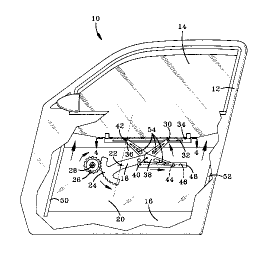
Fig. 1, a vehicle door 10 having an angled B-pillar 12
is shown. The door 10 has a movable window pane 14
which is shown fully retracted into a door cavity 16.
A door window regulator for raising and lowering the
glass pane 14 has a bent or curved lift arm 18 which is
pivotally connected at one end, to an interior base
panel 20 by a shaft 22. A segment gear 24 integrally
attached to the lift arm 18 at the end nearest the pivot
point of the lift arm has an arcuate row of teeth which
mesh with the teeth of pinion 26 connected to base panel
20 by pinion shaft 28. Pinion 26 is operatively con-
nected in a conventional manner to a motor (not shown)
or a manual crank (not shown) to effect rotation of the
pinion 26 and the lift arm 18. The end of the lift arm
opposite the segment gear 24 carries a roller or pin 30
which pivotally and slidably rides along a guideway or
channel 32 of a guide element 34 fixedly connected to
the window pane 14. Each of a pair of balance arms 36
and 38 is pivotally connected at one end to a central
pivot pin 40 at a point on the lift arm 18 intermediate
between the pin 30 and shaft 22. The central pivot
point 40 is preferably located so that it is always near
a vertical plane perpendicular with, and passing through
the center of mass of the window pane, regardless of the
extent to which the window pane has been raised or
lowered. A roller or pin 42 at the other end of forward
balance arm 36 pivotally, and optionally slidably
engages a guideway or channel 32 of guide element 34,
while the other end of rearward balance arm 38 carries
a roller or pin 44 which pivotally and slidably engages
a guideway or channel 46 of a guide element 48 secured
to the base panel 20. While the forward balance arm 36
2098557
_ - 6
is pivotally, and optionally slidably, engaging a
guideway 32, in the preferred embodiment, to allow for
greater adjustability and/or flexibility, the forward
balance arm can be pivotally secured to the window as
shown in Fig. 5. The guideways or channels 32 and 46
are substantially linear and preferably arranged so that
the longitudinal axes of the channels are substantially
horizontal.
Referring to Fig. 2, arrows are used to
indicate generally the direction of motion of the glass
and various regulator components when the glass pane is
being raised. Clockwise rotation of the pinion 26
causes the segment gear 24 to move in a counter clock-
wise direction which in turn causes the other end of the
lift arm 18 to rotate upwardly about shaft 22 lifting
the window pane 14. Forward and rearward glass-run
channels 50 and 52, respectively, guide the forward and
rearward edges of the window pane 14 as it is being
raised or lowered.
The bend of the lift arm 18 is formed by two
nonparallel substantially linear segments and is defined
such that a line connecting the pivot point at shaft 22
with the balance point at pivot pin 40 (arm segment A)
forms an angle with a line connecting the balance point
to pin 30 (arm segment B). This lift arm angle is
generally between 90 and 180. Preferably, the sum of
the lift arm angle and the angle formed by the B-pillar
with the vertical is about 180.
The radially distal portion of the lift arm 18
(arm segment B) is preferably about equal in length to
the forward balance arm, while the proximal portion of
the lift arm (arm segment A) is preferably about equal
in length to the rearward balance arm, so that the
balance point at pin 40 is situated substantially
directly below the center of mass of the window pane 14,
regardless of the extent to which the glass pane has
been raised or lowered. In accordance with the most
20985~
_ -- 7
preferred mode of the invention, both balance arms 36
and 38 and both portions of the lift arm are all of
equal length, with the regulator components arranged so
that the lift arm angle is about equal to the angle
formed by the two balance arms regardless of the extent
to which the window pane has been raised or lowered.
A characteristic of the door window regulator
disclosed herein is that the pivot point of the forward
balance arm which is connected to the window pane
travels along a substantially linear path which is
substantially parallel with the slanted window opening
edge of the B-pillar during raising or lowering of the
window pane. This characteristic of the invention is
most clearly illustrated in Figures 1-3, wherein the
orientation of the regulator components and the window
pane fully lowered at an intermediate position, and
almost fully raised, are shown respectively. The
forward balance arm 36 in cooperation with the other
regulator components thus ensures that as the window
pane is raised or lowered, the attitude of the window
pane remains substantially constant with respect to the
door and that the window is guided along a linear path
substantially parallel with the slanted window opening
edge of the B-pillar. The window pane maintains a
constant attitude by virtue of geometric relationship of
the lift arm 18 and the forward balance arm 36. In
particular, the lengths of the distal arm segment B and
of forward balance arm 36, as measured from the central
pivot point 40 to the sliding pivot point at which the
lift arm is connected to the window pane and the sta-
tionary pivot point at which the forward balance arm is
connected to the window pane respectively, are of
substantially equal length. The arm lengths in associa-
tion with the bend of the lift arm cooperate to keep the
window pane level and to smoothly direct it along a
linear path parallel to the window opening edge of the
B-pillar.
20985$7
-
-- 8
The smooth tracking of the window parallel to
the window opening edge of the B-pillar reduces fore and
aft stresses at the edges of the window. However, with
a curved window having an axis of curvature parallel
with the normal direction of forward motion of the
vehicle, there is an interaction between fore/aft
stresses and inboard/outboard stresses. Therefore, for
curved windows, the smooth tracking of the window
parallel to the window opening edge of the B-pillar also
helps to reduce inboard and outboard stresses on the
glass channel runs and weatherstrips.
In order to further reduce inboard and out-
board stresses on the glass-runs, glass-run weather
strips, and the regulator components, particularly when
a curved window pane having an axis of curvature paral-
lel to the normal direction of forward motion of the
vehicle is used, the central pivot point 40 is centrally
located in the door cavity substantially equidistance
between the vertical planes coincident with the longitu-
dinal directions of the guide elements 34 and 48 as
shown in Fig. 4. This central positioning of the pivot
point 40 provides for better balancing of the window
pane on the regulator and thereby aids in reducing
inboard and outboard stresses, as well as fore and aft
stresses.
Inboard and outboard stresses can be further
reduced by increasing the flexibility of the lift arms
by providing them with holes, slots or cutouts 54, or by
providing them with hinges 56 as shown in Fig. 5.
While in accordance with the Patent Statutes,
the best mode and preferred embodiment has been set
forth, the scope of the invention is not limited there-
to, but rather by the scope of the attached claims.