Sélection de la langue

Search

Sommaire du brevet 2098758 

Énoncé de désistement de responsabilité concernant l'information provenant de tiers

Une partie des informations de ce site Web a été fournie par des sources externes. Le gouvernement du Canada n'assume aucune responsabilité concernant la précision, l'actualité ou la fiabilité des informations fournies par les sources externes. Les utilisateurs qui désirent employer cette information devraient consulter directement la source des informations. Le contenu fourni par les sources externes n'est pas assujetti aux exigences sur les langues officielles, la protection des renseignements personnels et l'accessibilité.

Disponibilité de l'Abrégé et des Revendications

L'apparition de différences dans le texte et l'image des Revendications et de l'Abrégé dépend du moment auquel le document est publié. Les textes des Revendications et de l'Abrégé sont affichés :

  • lorsque la demande peut être examinée par le public;
  • lorsque le brevet est émis (délivrance).
(12) Demande de brevet: (11) CA 2098758
(54) Titre français: ARRACHE-PIEUX
(54) Titre anglais: POST PULLER
Statut: Réputée abandonnée et au-delà du délai pour le rétablissement - en attente de la réponse à l’avis de communication rejetée
Données bibliographiques
(51) Classification internationale des brevets (CIB):
  • E02D 09/00 (2006.01)
  • E04H 17/26 (2006.01)
(72) Inventeurs :
  • SCHATZ, LESTER R. (Etats-Unis d'Amérique)
(73) Titulaires :
  • LESTER R. SCHATZ
(71) Demandeurs :
(74) Agent: SMART & BIGGAR LP
(74) Co-agent:
(45) Délivré:
(22) Date de dépôt: 1993-06-18
(41) Mise à la disponibilité du public: 1994-09-09
Licence disponible: S.O.
Cédé au domaine public: S.O.
(25) Langue des documents déposés: Anglais

Traité de coopération en matière de brevets (PCT): Non

(30) Données de priorité de la demande:
Numéro de la demande Pays / territoire Date
08/027,807 (Etats-Unis d'Amérique) 1993-03-08

Abrégés

Abrégé anglais


Abstract of the Disclosure
A post puller for use with a tractor loader having a loader
bucket pivotally mounted thereon and a grapple fork pivotally
mounted on the loader bucket comprising a post receiver mounted
on the bucket and a clamping arm operatively secured to the
grapple fork so that the post to be pulled may be clamped
between the post receiver and the post clamping arm. Upward
movement of the loader bucket by the tractor loader causes the
post to be pulled from the ground. The post puller is adapted
to accommodate wood posts of various diameters as well as steel
posts.

Revendications

Note : Les revendications sont présentées dans la langue officielle dans laquelle elles ont été soumises.


The embodiments of the invention in which an
exclusive property or privilege is claimed are defined as
follows:
1.
In combination,
a tractor having a forward end and a rearward end,
a front loader mounted on said tractor,
said front loader including a loader frame means, a pair of boom
arms pivotally mounted to said loader frame means and
extending forwardly therefrom, each of said boom arms having
a forward end, a first hydraulic cylinder means for
pivotally moving said boom arms with respect to said loader
frame means so that the forward ends of said boom arms may
be selectively raised or lowered,
a loader bucket pivotally mounted, about a horizontal axis, on
the forward ends of boom arms and having upper and lower
ends, and opposite sides,
a second hydraulic cylinder means for pivotally moving said
loader bucket means with respect to said boom arms,
a grapple fork means pivotally mounted, about a horizontal axis,
at the upper end of said loader bucket means and being
movable from a first upper position to a second lower
position relative to said loader bucket means,
a third hydraulic cylinder means for pivoting said grapple fork
means relative to said loader bucket means,
and a post puller means for pulling upstanding posts from the
ground,
-11-

said post puller means comprising a post receiving means mounted
at one side of said loader bucket means which has a
forwardly presented opening adapted to receive the post to
be pulled therein,
and an arm means operatively connected to said grapple fork
means for movement therewith, said arm means extending from
said grapple fork means so that said arm means will be
spaced forwardly of said post receiving means when said
grapple fork means is in its first upper position and so
that said arm means will be closely positioned adjacent the
said post receiving means, when said grapple fork means is
moved to its said second lower position, to clamp the post
to be pulled into said post receiving means,
the upward movement of said loader bucket means, after the post
has been clamped into said post receiving means, causing the
post to be pulled from the ground.
2.
The combination of claim 1 wherein said post receiving means
includes a V-shaped jaw means.
3.
The combination of claim 2 wherein said jaw means comprises
first and second jaw members having inner and outer surfaces,
and wherein said inner surfaces of said jaw members have post
gripping surfaces provided thereon.
-12-

4.
The combination of claim 1 wherein said arm means includes
an upper end which is secured to said grapple fork means and a
lower end which is positioned closely above said post receiving
means when said grapple fork means has been moved to its said
second lower position.
5.
The combination of claim 4 wherein the lower end of said arm
means has a rear end which has a gripping surface provided
thereon.
6.
The combination of claim 3 wherein said jaw members are
horizontally spaced and have rearward and forward ends, an
upstanding finger means having upper and lower ends, the lower
end of said finger means being positioned between said jaw
members at the rearward ends thereof and being pivoted, about a
horizontal axis, with respect to said jaw members, the upper end
of said finger means engaging the post to be pulled, when the
post is clamped into said jaw members, to aid in clamping the
post into the post receiving means.
7.
In combination with a tractor having a forward end and a
rearward end, a front loader mounted on said tractor, said front
loader including a loader frame means, a pair of boom arms
pivotally mounted to said frame means and extending forwardly
-13-

therefrom, each of said boom arms having a forward end, a first
hydraulic cylinder means for pivotally moving said boom arms
with respect to said loader frame means so that the forward ends
of said boom arms may be selectively raised or lowered, a loader
bucket pivotally mounted, about a horizontal axis, on the
forward ends of boom arms and having upper and lower ends, and
opposite sides, a second hydraulic cylinder means for pivotally
moving said loader bucket means with respect to said boom arms,
a grapple fork means pivotally mounted, about a horizontal axis,
at the upper end of said loader bucket means and being movable
from a first upper position to a second lower position relative
to said loader bucket means, a third hydraulic cylinder means
for pivoting said grapple fork means relative to said loader
bucket means, comprising,
a post puller means for pulling upstanding posts from the
ground,
said post puller means comprising a post receiving means mounted
at one side of said loader bucket means having a forwardly
presented opening adapted to receive the post to be pulled
therein,
and an arm means operatively connected to said grapple fork
means for movement therewith, said arm means extending from
said grapple fork means so that said arm means will be
spaced forwardly of said post receiving means when said
grapple fork means is in its first upper position and so
-14-

that said arm means will be closely positioned adjacent the
said post receiving means, when said grapple fork means is
moved to its said second lower position, to clamp the post
to be pulled into said post receiving means,
the upward movement of said loader bucket means, after the post
has been clamped into said post receiving means, causing the
post to be pulled from the ground.
8.
The combination of claim 7 wherein said post receiving means
includes a V-shaped jaw means.
9.
The combination of claim 8 wherein said jaw means comprises
first and second jaw members having inner and outer surfaces,
and wherein said inner surfaces of said jaw members have post
gripping surfaces provided thereon.
10.
The combination of claim 7 wherein said arm means includes
an upper end which is secured to said grapple fork means and a
lower end which is positioned closely above said post receiving
means when said grapple fork means has been moved to its said
second lower position.
11.
The combination of claim 10 wherein the lower end of said
arm means has a rear end which has a gripping surface provided
thereon.
-15-

12.
The combination of claim 9 wherein said jaw members are
horizontally spaced and have rearward and forward ends, an
upstanding finger means having upper and lower ends, the lower
end of said finger means being positioned between said jaw
members at the rearward ends thereof and being pivoted, about a
horizontal axis, with respect to said jaw members, the upper end
of said finger means engaging the post to be pulled, when the
post is clamped into said jaw members, to aid in clamping the
post into the post receiving means.
13.
In combination,
a tractor having a forward end and a rearward end,
a front loader mounted on said tractor,
said front loader including a loader frame means, a pair of boom
arms pivotally mounted to said frame means and extending
forwardly therefrom, each of said boom arms having a forward
end, a first hydraulic cylinder means for pivotally moving
said boom arms with respect to said loader frame means so
that the forward ends of said boom arms may be selectively
raised or lowered,
a loader bucket pivotally mounted, about a horizontal axis, on
the forward ends of boom arms and having upper and lower
ends, and opposite sides,
a second hydraulic cylinder means for pivotally moving said
loader bucket means with respect to said boom arms,
-16-

first means pivotally mounted, about a horizontal axis, at the
upper end of said loader bucket means and being movable from
a first upper position to a second lower position relative
to said loader bucket means,
a third hydraulic cylinder means for pivoting said first means
relative to said loader bucket means,
and a post puller means for pulling upstanding posts from the
ground,
said post puller means comprising a post receiving means mounted
at one side of said loader bucket means having a forwardly
presented opening adapted to receive the post to be pulled
therein,
and an arm means operatively connected to said first means for
movement therewith, said arm means extending from said first
means so that said arm means will be spaced forwardly of
said post receiving means when said first means is in its
first upper position and so that said arm means will be
closely positioned adjacent the said post receiving means,
when said first means is moved to its said second lower
position, to clamp the post to be pulled into said post
receiving means,
the upward movement of said loader bucket means, after the post
has been clamped into said post receiving means, causing the
post to be pulled from the ground.
-17-

14.
The combination of claim 13 wherein said first means
comprises a materials handling apparatus.
-18-

Description

Note : Les descriptions sont présentées dans la langue officielle dans laquelle elles ont été soumises.

3 ~3 , ,
1~ B~kground of ~he Inven~i-n
1. Field of the Invention
This invention relates to a post puller and more
particularly to a post puller which is mounted on a materials
handling attachment positioned on the forward end of a tractor
loader.
2. Background Art
Many types of post pullers have been previously
provided for pulling posts from the ground whether those posts
be of the wooden type or of the steel type. Some of the post
21~ pullers have been mounted on the vertically movable 3-point
hitches of tractors. For example, U.S. Patent Nos. 4,226,402
and 4,256,286 disclose such devices. Although the devices of
U.S. Patent Nos. 4,226,402 and 4,256,286 may work
2s ¦natlsfno ily, it is believed thnt devi~es of this type nre not
::
'

2 0 ~ 8
convenient to use since they require that the tractor be backed
¦into position, relative to the post to be pulled, which
¦necessarily requires that the tractor operator turn around in
¦his seat to ob~erve the operation. Further, when the post
¦pulling device is mounted on the 3-point hitch of the tractor,
¦the tractor hitch may not be used for any other purpose.
¦ Other types of post pulling devices have been described
¦which are specifically designed as a single-use vehicle. For
¦example, see U.S. Patent No. 4,371,018 which discloses such a
¦device. The device of the '018 patent is obviously quite
¦expensive and is not an add-on device.
Summary of the Invention
A post puller is described which is mounted on the bucket of
a tractor loader as a piece of nadd-on~ equipment. When the
post puller of this invention is mounted on the tractor loader,
the tractor loader may be used in its conventional fashion
without any interference from the post puller. The post puller
comprises a V-shaped jaw means which is secured to one side of
the loader bucket and which is adapted to receive either a wood
2~) post or a steel post therebetween. A clamping arm is
operatively pivotally secured to a grapple fork mounted on the
loader bucket of the tractor loader and has a lower end which is
adapted to force or clamp the post into the jaw means. When the
post is clamped into the jaw means by the lower end of the
clamping arm, the loader bucket is moved vertically upwardly

2 ~ ~ ~3 t`~
which causes the post to be pulled from the ground.
It i8 therefore a principal obiect of the invention to
provide an impro~ed post puller.
Another object of the invention is to provide a post puller
which may be mounted on a tractor loader and which does not
interfere with the normal operation of the tractor loader.
A further object of the invention is to provide a post
puller which is an add-on piece of equipment to a conventional
tractor loader.
Still another object of the invention is to provide a post
puller which may be mounted on a bucket of a tractor loader to
enable the tractor operator to pull posts without leaving the
tractor.
Still another object of the invention is to provide a post
1~ puller which is adapted to accommodate posts of different
configurations and sizes.
Still another object of the invention is to prov~de a post
puller which is economical of manufacture and durable in use.
These and other objects of the present invention will be
2~ apparent to those skilled in the art.
Brief Description of the Drawings
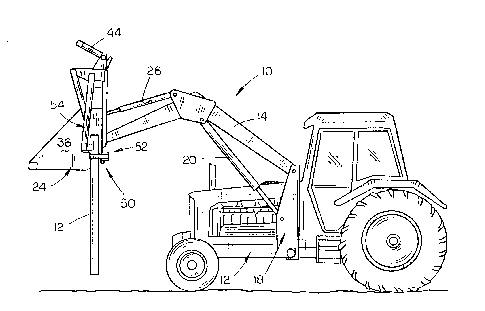
Figure 1 is a front perspective view of the post puller of
this invention mounted on a tractor loader;
Figure 2 is an exploded perspective view of the post puller
of this inventicn;
_3_

rJ ` (~
Figure 3 is a side view of the post puller which illustrate
a post having been received by the post receiving portion of the
invention and prior to any clamping action:
Figure 4 is a view similar to Figure 3 except that the post
S has been clamped into the post puller;
Figure 5 i~ an enlarged sectional view as seen in lines 5-5
of Figure 4;
Figure 6 is a sectional view seen-on lines 6-6 of Figure 5;
~ igure 7 is a view similar to Figure 5 except that a steel
l(~ post has been received between the jaws rather than a wooden
post;
Figure 8 is a sectional view seen on lines 8-8 of Figure 7;
Figure 9 is a side view illustrating the post puller
l connected to a post; and
I Figure 10 is a view similar to Figure 9 except that the post
has been removed from the ground through the raising of the
loader bucket.
DescriDtion of the Preferred Embodiment
In the drawings, the numeral 10 refers to a conventional
2~ tractor loader or front-end loader as they are sometimes
called. Loader 10 is mounted on a conventional tractor 12
,having the conventional hydraulic system, controls, etc. Loader
10 includes a pair of boom arms or loader arms 14 and 16 which
are pivotally connected at their rearward ends to the loader
2s frame 18. Hydraulic cylinders 20 and 22 are provided between
-4-

1 2 3 r~ ~ r~ ! ~
¦the loader frame 18 and the arms 14 and 16 to raise and lower
¦the arms 14 and 16 in conventional fashion. A conventional
¦loader bucket 24 is pivotally mounted, about a horizontal axis,
¦to the forward ends of arms 14 and 16 in conventional fashion.
5 IA pair of hydraulic cylinders 26 and 28 interconnect the arms 14
¦and 16 and the rearward end of the loader bucket 24 to pivotally
¦move the bucket 24, about a ihorizontal axis, relative to the
¦forward ends of the arms 14 and 16. For purposes of
¦description, loader bucket 24 will be described as including a
¦bottom wall 30, upper wall 32, back wall 34, and opposite side
¦walls 36 and 38.
¦ The numeral 40 refers to a conventional grapple fork
¦attachment which is mounted on the bucket 24 and which is
¦pivotally mounted, about a horizontal axis, to the bucket 24, so
¦that the grapple fork 40 may be pivotally moved between the
¦positions of Figures 3 and 4. It should be noted that Figure 4
¦does not illustrate the grapple fork in its lowermost position.
¦Conventionally, the lower ends of the forks 42 would be
positioned closely adjacent the forward end of bottom wall 30
2~) when the fork 40 is in its lowermost condition. A hydraulic
cylinder 44 is provided on the grapple fork 40 for pivotally
moving the grapple fork 40 from its upper (open) position to its
lower (closed) position.
As seen in the drawings, grapple fork 40 includes a
horizontally disposed shaft or pipe 46 which is pivotally or
2s

- ~
2 ~ ',3
I rotatably mounted ~n a frame 48 attached to the rearward side of
the bucket 24. Shaft or pipe 46 is rotated relative to the
frame 48 when the cylinder 44 is actuated.
The numeral 50 refers generally to the post puller of this
invention and essentially comprises a post receiving portion or
means 52, in the form of a ~aw means, and a clamping arm portion
54. Clamping arm 54 portion includes a shaft 56 which is
secured to the outer end of shaft 46 for rotation therewith.
Arm 58 is secured, by welding or the like, to the outer end of
shaft 56 and extends transversely therefrom. Braces 60 and 62
I~)
are provided for strengthening purposes. The lower end of arm
58 has a plate or bar 64 secured thereto as seen in Figure l.
Plate 64 is provided with an irregular gripping surface 66 in
the form of teeth or the like to aid in gripping the post to be
.
pulled. It should be noted that plate 64 is positioned so as to
pass over the upper end of the post receiving portion 52 so that
the post puller will not interfere with the normal operation of
the grapple hook 40.
Post receiving portion 52 includes a horizontally disposed
2() bar 68 which is welded to the outer surface of back wall 34
adjacent side wall 36. Bar 68 has a pair of openings 70 and 72
formed therein adapted to receive bolts 74 and 76 respectively.
Bar 78 is removably connected to the bar 68 by means of the
bolts 74 and 76 extending through openings 80 and 82
respectively and being secured by means of nuts 84 and 86. A
-6-
:,

~ ~ '''5~ '
I air of paced-apart collars 88 and 90 are welded to the
nderside of bar 78 adjacent the outer end thereof and which are
adapted to receive the sleeve 92 therebetween. Sleeve 92 ~s
pivotally positioned relative to collars 88 and 90 by means of
the pivot pin 94 extending through collar 90, sleeve 92 and
collar 88. Sleeve 92 is secured to the lower rearward side of
gripping finger 96 which extends upwardly and forwardly
therefrom. The upper end of finger 96 is provided with an
irregular gripping ~urface 98 provided thereon as illustrated in
Figure 2. Stop pin or shaft 100 is secured to the upper
rearward side of finger 96 for a purpo~e to be described
hereinafter.
A pair of jaw members 102 and 104 are welded to the upper
surface of bar 78 adjacent the outer end thereof and extend
forwardly therefrom in a diverging fashion to essentially define
a V-shape. Jaw members 102 and 104 are provided with irregular
gripping surfaces 106 and 108 on the inner surfaces thereof for
gripping the po~t to be pulled. Plate llo is secured to and
extends between the upper rearward ends of jaw members 102 and
2~ 104 as seen in Figure 2. Finger 96 extends upwardly and
~orwardly between jaw members 102 and 104 near the rearward end
thereof so that its upper end is disposed above the jaw members
102 and 104. Stop pin 100 i5 positioned above jaw members 102
and 104 and is adapted to engage the same to limit the forward
pivotal movement of the finger 96 when a post is not received
2s

IJ'`~ }
between the ~aw members 102 and 104.
In operation, the tractor and loader may be used in a
conventional manner without the add-on post puller interfering
with any operation thereof. When it is desired to pull a wood
post 112 ~rom the ground, grapple fork 40 is pivotally moved to
its upper or open position by the hydraulic cylinder 44 so that
the arm 58 is pivotally moved upwardly and forwardly from the
post receiving portion 52. The tractor is driven 50 that the
post 112 is received between the V-shaped ~aw members 102 and
104. The V-shape of the jaw members not only assists in wedging
the post therebetween, but also enables the jaw members to
receive wood posts having various diameters.
When the post 112 has been positioned between the jaw
members 102 and 104, hydraulic cylinder 44 is actuated to cause
IS the grapple fork to pivot from its upper or open position of
Figure 3 to the position of Figure 4. The lowering of the
grapple fork by the hydraulic cylinder 44 causes the rearward
end of bar 64 to engage the post 112 to wedge or clamp the post
between bar 64 and the jaw members 102 and 104. The clamping of
2~ the post 112 between the jaws 102 and 104 by the bar 64 causes
the finger 96 to pivot upwardly and rearwardly. The loader arms
14 and 16 are then raised by the hydraulic cylinders 20 and 22
which causes the post to be pulled from the ground as
illustrated in ~igure lo. As the loader bucket moves upwardly,
2S the upper end of the finger 96 tends to bite or dig into the
-8-
.. , . , ~ . j .. ... . ~ . .. . ....... ....... . . ... .

: ::
2 ~` '` 37 ` 8
post to further clamp the post in position.
The post puller of this invention is also adapted to
accommodate steel posts such as illustrated in Figures 7 and 8.
The steel post 114 is received between the ~aw members 102 and
S 104 as illustrated in Figure 7 with a portion of the post 114
being brought into engagement with the finger 96. The bar 64
wedges the post 114 between bar 64, the jaw members 102, 104 and
the finqer 96 so that the post is securely clamped or locked
into position in the post puller. The bucket 24 is raised as
previously described to pull the post from the ground.
Thus it can be seen that a novel add-on post puller has been
prov~ded which may be added to a conventional tractor loader so
that the tractor loader may be used to pull posts whether the
posts be wood, steel, etc. The position of the post puller on
lS the bucket is such that the tractor operator may conveniently
view the same and may successively pull posts without leaving
the tractor. Although the post puller is ideally suited for use
on a loader bucket having a grapple fork pivotally mounted
thereon, the clamping arm 54 could be pivotally secured to other
2~) attachments or other structure on the tractor loader bucket even
if a grapple fork were not being used. For example, the arm 54
could be pivotally secured to other mounting structure on the
bucket with a separate hydraulic cylinder being used to
manipulate the same. However, such a modification would result
in the need for an additional mounting structure, hydraulic
_9_

2 ~ ~:
cylinder, etc.
Thus it can be seen that the post puller of this invention
accomplishes at least all of its stated objectives.

Dessin représentatif
Une figure unique qui représente un dessin illustrant l'invention.
États administratifs

2024-08-01 : Dans le cadre de la transition vers les Brevets de nouvelle génération (BNG), la base de données sur les brevets canadiens (BDBC) contient désormais un Historique d'événement plus détaillé, qui reproduit le Journal des événements de notre nouvelle solution interne.

Veuillez noter que les événements débutant par « Inactive : » se réfèrent à des événements qui ne sont plus utilisés dans notre nouvelle solution interne.

Pour une meilleure compréhension de l'état de la demande ou brevet qui figure sur cette page, la rubrique Mise en garde , et les descriptions de Brevet , Historique d'événement , Taxes périodiques et Historique des paiements devraient être consultées.

Historique d'événement

Description Date
Inactive : CIB de MCD 2006-03-11
Le délai pour l'annulation est expiré 2001-06-18
Demande non rétablie avant l'échéance 2001-06-18
Réputée abandonnée - omission de répondre à un avis sur les taxes pour le maintien en état 2000-06-19
Inactive : Abandon.-RE+surtaxe impayées-Corr envoyée 2000-06-19
Demande publiée (accessible au public) 1994-09-09

Historique d'abandonnement

Date d'abandonnement Raison Date de rétablissement
2000-06-19

Taxes périodiques

Le dernier paiement a été reçu le 1999-06-04

Avis : Si le paiement en totalité n'a pas été reçu au plus tard à la date indiquée, une taxe supplémentaire peut être imposée, soit une des taxes suivantes :

  • taxe de rétablissement ;
  • taxe pour paiement en souffrance ; ou
  • taxe additionnelle pour le renversement d'une péremption réputée.

Les taxes sur les brevets sont ajustées au 1er janvier de chaque année. Les montants ci-dessus sont les montants actuels s'ils sont reçus au plus tard le 31 décembre de l'année en cours.
Veuillez vous référer à la page web des taxes sur les brevets de l'OPIC pour voir tous les montants actuels des taxes.

Historique des taxes

Type de taxes Anniversaire Échéance Date payée
TM (demande, 4e anniv.) - petite 04 1997-06-18 1997-05-29
TM (demande, 5e anniv.) - petite 05 1998-06-18 1998-05-27
TM (demande, 6e anniv.) - petite 06 1999-06-18 1999-06-04
Titulaires au dossier

Les titulaires actuels et antérieures au dossier sont affichés en ordre alphabétique.

Titulaires actuels au dossier
LESTER R. SCHATZ
Titulaires antérieures au dossier
S.O.
Les propriétaires antérieurs qui ne figurent pas dans la liste des « Propriétaires au dossier » apparaîtront dans d'autres documents au dossier.
Documents

Pour visionner les fichiers sélectionnés, entrer le code reCAPTCHA :


Pour visualiser une image, cliquer sur un lien dans la colonne description du document. Pour télécharger l'image (les images), cliquer l'une ou plusieurs cases à cocher dans la première colonne et ensuite cliquer sur le bouton "Télécharger sélection en format PDF (archive Zip)" ou le bouton "Télécharger sélection (en un fichier PDF fusionné)".

Liste des documents de brevet publiés et non publiés sur la BDBC .

Si vous avez des difficultés à accéder au contenu, veuillez communiquer avec le Centre de services à la clientèle au 1-866-997-1936, ou envoyer un courriel au Centre de service à la clientèle de l'OPIC.


Description du
Document 
Date
(aaaa-mm-jj) 
Nombre de pages   Taille de l'image (Ko) 
Abrégé 1994-09-08 1 55
Revendications 1994-09-08 8 446
Dessins 1994-09-08 5 175
Description 1994-09-08 10 562
Dessin représentatif 1998-08-24 1 17
Rappel - requête d'examen 2000-02-21 1 119
Courtoisie - Lettre d'abandon (taxe de maintien en état) 2000-07-16 1 184
Courtoisie - Lettre d'abandon (requête d'examen) 2000-07-30 1 172
Taxes 1997-05-28 1 39
Taxes 1996-05-30 1 42
Taxes 1995-05-31 1 38