Sélection de la langue

Search

Sommaire du brevet 2098856 

Énoncé de désistement de responsabilité concernant l'information provenant de tiers

Une partie des informations de ce site Web a été fournie par des sources externes. Le gouvernement du Canada n'assume aucune responsabilité concernant la précision, l'actualité ou la fiabilité des informations fournies par les sources externes. Les utilisateurs qui désirent employer cette information devraient consulter directement la source des informations. Le contenu fourni par les sources externes n'est pas assujetti aux exigences sur les langues officielles, la protection des renseignements personnels et l'accessibilité.

Disponibilité de l'Abrégé et des Revendications

L'apparition de différences dans le texte et l'image des Revendications et de l'Abrégé dépend du moment auquel le document est publié. Les textes des Revendications et de l'Abrégé sont affichés :

  • lorsque la demande peut être examinée par le public;
  • lorsque le brevet est émis (délivrance).
(12) Brevet: (11) CA 2098856
(54) Titre français: OUTIL DE LEVAGE A EXTREMITE LIBRE AMELIOREE
(54) Titre anglais: IMPROVED OPEN END CONSTRUCTION FOR JACK
Statut: Périmé et au-delà du délai pour l’annulation
Données bibliographiques
(51) Classification internationale des brevets (CIB):
  • B66F 03/22 (2006.01)
  • B66F 03/08 (2006.01)
(72) Inventeurs :
  • ENGEL, DARRYL L. (Etats-Unis d'Amérique)
  • SCOVILLE, JOHN R. (Etats-Unis d'Amérique)
(73) Titulaires :
  • UNIVERSAL TOOL & STAMPING COMPANY, INC.
(71) Demandeurs :
  • UNIVERSAL TOOL & STAMPING COMPANY, INC. (Etats-Unis d'Amérique)
(74) Agent: CASSAN MACLEAN
(74) Co-agent:
(45) Délivré: 1999-01-19
(22) Date de dépôt: 1993-06-21
(41) Mise à la disponibilité du public: 1994-09-18
Requête d'examen: 1995-11-29
Licence disponible: S.O.
Cédé au domaine public: S.O.
(25) Langue des documents déposés: Anglais

Traité de coopération en matière de brevets (PCT): Non

(30) Données de priorité de la demande:
Numéro de la demande Pays / territoire Date
08/032,095 (Etats-Unis d'Amérique) 1993-03-17

Abrégés

Abrégé français

Une amélioration est apportée à une terminaison ouverte pour un vérin. Cette terminaison est constituée par des languettes orientées à angle droit par rapport aux côtés des canaux, permettant d'insérer une cheville dans cette terminaison. la suite de cette opération, on replie les languettes de façon qu'elles soient orientées dans le plan des côtés des canaux, de sorte que la cheville soit immobilisée dans la terminaison. On peut également monter des anneaux partiels aux ouvertures des terminaisons des canaux afin de fournir des surfaces d'appui aux chevilles.


Abrégé anglais


An improved open end construction for jacks which
provides for tabs which extend at right angles to the side
surfaces of the channel members so as to allow pivot pins to
be received in the open ends after which the tabs are bent so
that they lie in the plane of the side surfaces of the channel
members so as to lock the pivot pin in the ends of the channel
assembly. Also, partial flanges can be formed about the
openings in the ends of the channel members so as to provide
bearing surfaces for the pivot pins.

Revendications

Note : Les revendications sont présentées dans la langue officielle dans laquelle elles ont été soumises.


WHAT IS CLAIMED IS:
1. A scissors jack made by a process comprising the steps
(a) through (c) defined herein wherein said jack comprises a base
member, first and second lower channel members with side planar
surfaces and with their lower ends pivotally attached to said
base member and said first and second channel members formed with
meshing gears, a support member, first and second upper channel
members with side planar surfaces and with their upper ends
pivotally attached to said support member, a threaded trunnion
formed with a first pivot pin, a plain trunnion formed with a
second pivot pin, the upper end of said first lower channel
member and the lower end of said first upper channel member
pivotally mounted on said first pivot pin of said threaded
trunnion and the upper end of said second lower channel member
and the lower end of said second upper channel member pivotally
mounted on said second pivot pin of said plain trunnion, a shaft
which extends through said plain trunnion and has a threaded
portion received in said threaded trunnion, and wherein the ends
of said first and second upper and lower channel members are
pivotally attached by said process to said first and second pivot
pins, said process comprising the steps: (a) forming pin
receiving openings and adjoining tab portions that are bent
ninety degrees relative to the side planar surfaces in the ends
of said first and second upper and lower channel members; (b)
inserting said first and second pivot pins into said pin
- Page 1 of Claims -

receiving openings; and, (c) bending said tab portions so that
they lie in the plane of said side planar surfaces of said first
and second upper and lower channel members.
2. A scissors jack according to claim 1 comprising a partial
bearing surface for said pivot pins which extends beyond the side
planar surface of said channel member.
3. A scissors jack according to claim 2 comprising a curved
portion between the opposite ends of said partial bearing surface
and two of said tab portions.
- Page 2 of Claims -

Description

Note : Les descriptions sont présentées dans la langue officielle dans laquelle elles ont été soumises.

~ 209~5~
~ P E C I F I C A T I O N
This invention relates to scissors jacks with open end
construction.
one means of assembling a jack is by using open end
construction. Such open end construction is shown in U. S.
Patent 4,802,653, assigned to the assignee of the present
invention. While this method is normally used at the trunion
ends of the jack, open end ~onstruction could be used at any
pivot point on the jack. In the structure illustrated in
patent 4,802,653, the open ends of the legs are bent around
the pivot point so as to retain the pivot shaft in the
opening. In the typical trunion-channel assembly using open
end design as shown in Patent 4,802,653, once the trunion is
inserted into the open end, the end tabs are simply bent
toward each other, thus locking the trunion axle in place.
Under normal conditions, this is very satisfactory since the
linkage members of a jack are in compression when lifting a
vehicle. The weakness of this design is that if a linkage
member is loaded in tension, the tabs can be spread open again
and let the assembly come apart. There are two reasons for
this. First, the cross-sectional area of the tabs must ~e
small enough to allow the tabs to bend and therefore are
limited to how strong they could be made. Second, when the
channel is placed in tension, the tensile force is applied to
the tabs in the same plane that the tabs are bent. 5O as to
prevent the tabs from spreading in the prior art jack, it is
necessary to use higher strength steel than the jack would
normally acquire.
The present invention provides an open end jack
arrangement wherein tabs are bent at 90~ to the plane to which
the tensile force is applied in. Any tensile force is applied
'.; ~

2 ~
through a cross-section that is larger and is therefore
stronger as compared to the prior art open end design.
It is an object of the present invention to provide an
improved open end channel assembly for a jack which is formed
with tabs which extend normal to the sides of the channel
member during assembly and after the trunion has been placed
in position, the tabs are bent toward each other so as to
firn~ly lock the trunion in position.
It is another object of the invelltion to provide a
partial flange about the pivot shaft so as to provide a
bearing surface so as to strengthen the jacX because of the
increased bearing surface.
It is yet another object of the invention to provide an
improved open end construction for a jack which allows the
tabs of the upper and lower adjacent channel members which are
provided with tabs that extend in opposite directions to be
assem~led by applying force to close the tabs.
other objects, features and advantages of the invention
will be readily apparent from the following description of
certain preferred embodiments thereof taken in conjunction
with the accompanying drawings although variations and
modifications may be effected without departing from the
spirit and scope of the novel concepts of the disclosure, and
in which:
2 5 ON THE DR~WIN~:S ~
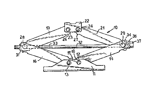
FIG. 1 is a side plan view of a scissors jack according
to the invention;
FIG. 2 is a perspective view illustrating a channel
assembly with the improved invention;
FIG. 3 is a partial cut-away view illustrating the tabs
after they are bent to the locking position;
':' '

209~
FIG. 4 is a plan view illustrating the tabs in the locked
position;
FIG. 5 illustrates a modified form of the invention;
FIG. 6 illustrates a further modification of the
invention; and
FIG. 7 illustrates yet another modification of the
invention.
FIGS. 1-4 show the first embodiment of the invention as
applied to a scissors-type jack. As shown in FIG. 1, a base
11 pivotally supports lower channel members 14 and 16 with
pivot pins 12 and 13. The channels 14 and 16 are formed with
gear teeth 17 and 18 which mesh in a conventional manner.
The opposite ends o~ the channels 14, 16 are pivotally
connected by pins 28 and 29 to upper channel members 19 and
21. Pin 2~ is part of a threaded trunnion 31. The trunion
31 is mounted between the channels 16 and 19 and is formed
with a threaded opening in which the threaded portion 33 of
a shaft 32 can be received. Pin 29 is part of an open
trunnion 34. The trunnion 34 is formed with an opening
through which the shaft 32 extends. The shaft 32 carries a
bearing 36 and a drive member 37 for rotating the shaft 32 so
as to raise and lower the jack is attached to the end of shaft
32. Upper channel members 19 and 21 are connected by gears
26 and 27 and their upper ends are pivotally connected to a
support member 22 by pins 23 and 24. The support member 22
engages a portion of a vehicle so as to raise it.
The present invention relates to the manner in which the
ends of the channel members 14, 16, 19 and 21 are attached to
the pivot pins 28 and 29. FIGS. 2, 3 and 4 are detail views
illustrating the first embodimentO The channel 19 has a top
portion 19 and downwardly extending side portions l9a and l9b.
The gears 26 and 26a mesh with the gears 27 of the upper

2~988~ :
channel assembly member 21. The end of the channel member 19
is formed so as to receive the pivot pin 28. An opening is
formed between the extending portions 43 and 44 and tabs 47
and 48 are formed and are bent transversely of the plane of
the side l9a of the channel member. It is to he realized that
the tabs may be bent outwardly or inwardly. Openings 49 and
51 of generally arcuate shape are formed and join with a
partial flange 46 which is formed so as to be bent outwardly
at 90~ to the side portion l9a as shown in FIG. 2. An opening
is also formed in side portion l9b so as to ~orm a partial
flange 46a adjacent an opening 51a. Outwardly extending tabs
47a and ~8a which extend from ends 43a and 44a are also
formed. The lower channel 16 is also ~ormed with similar
ends. Channels 14 and 21 are also formed with slotted ends,
partial flanges and tabs.
As shown in FIGS. 3 and 4, as the jack is being
assembled, the pivot pins 28 and 29 are extended through the
openings in the channel members 16, 19, 14 and 21 so that they
rest against the partial flanges 46 and 46a and then the tabs
47, 48, 47a and 48a are bent to the positions shown in FIG.
3 so as to hold the pivot pin 28 firmly within the end of the
channel member 19. FIG. 4 is an end view illustrating the
pivot pin Z8 mounted in the end of the channel member 19 in
the locked position. The other three channel members are
mounted to the pivot pins 28 and 29 in a similar manner
With the invention, the tabs 47 and 48 are bent at 90~ to
the plane to which the tensile force is appli~d. The tensile
~orce is applied through a cross-sectional area that is larger
and therefore the jack is stronger than could be obtained with
the current end design.
The partial flange 46 increases the load bearing capacity
of the channel by providing-increased contact area for the
.

~ 2~988~
trunion pin or axle. The partial ~lange could be used on any
pivot point in the jack. In FIG. 3, the partial flange is
shown as being separated from the closure tabs, buk the
partial flange and the tabs could be connected. The partial
flange can also function as a spacer providing a space for the
opened closure tab. FIG. 5 illust~ates how the partial flange
could be used with a trunion 31 that has a shoulder 69 at the
end of the pivot 46. The other end of pin 46 has a shoulder
71 as shown in FIG. 5.
It is to be realized, of course, that the open end side
extending tabs and the partial flange could be used
independent of each other, although they are shown in
combination in FIGS. 2-6.
FIG. 6 illustrates a modification of the closure tab
shown in FIGS. 1-5 wherein the tabs are modified as shown to
have two bended portions 86 and 88 and 87 and 89 such that the
first portions of the tabs 87 and 86 can be bent so as to be
aligned with the plane of the surface l9a after the shaft has
been placed in position and the portions 88 and 89 extend
substantially at right angles out from the surface l9a so as
to provide spacers for the flanges 69 and 71 shown in FIG. 5.
The tabs 86a, 87a, 88a and 89a are similarly arranged.
FIG. 7 illustrates how two linkage channel members 16 and
19 can be assembled. When in tha opened position, the tabs
101 and 102 of one channel 16 extend outwardly and the tabs
103 and ~04 of channel 19 extend inwardly. Thus, the tabs of
the two channel extend in the opposite direction and aEter the
pivot pin 29 is placed in position, the tabs 101, 102, ~03 and
104 are bent to the closed position by moving a block parallel
to the sides of the channels with a bent tip which will
increase the force applied onto the tabs. Normally, the
channel 19 is received in the lower channel 16 as shown~
.

2 0 ~
Thus, the tabs and/or the flanges can be bent outwardly or
inwardly on the channel members.
It is seen that the present invention provides an
improved end construction for jacks and although it has been
described with respect to preferred embodiments, it i~ not to
be so limited as changes and modifications can be made therein
which are within the full intended scope as defined by the
appended claims.

Dessin représentatif
Une figure unique qui représente un dessin illustrant l'invention.
États administratifs

2024-08-01 : Dans le cadre de la transition vers les Brevets de nouvelle génération (BNG), la base de données sur les brevets canadiens (BDBC) contient désormais un Historique d'événement plus détaillé, qui reproduit le Journal des événements de notre nouvelle solution interne.

Veuillez noter que les événements débutant par « Inactive : » se réfèrent à des événements qui ne sont plus utilisés dans notre nouvelle solution interne.

Pour une meilleure compréhension de l'état de la demande ou brevet qui figure sur cette page, la rubrique Mise en garde , et les descriptions de Brevet , Historique d'événement , Taxes périodiques et Historique des paiements devraient être consultées.

Historique d'événement

Description Date
Inactive : CIB de MCD 2006-03-11
Le délai pour l'annulation est expiré 2002-06-21
Lettre envoyée 2001-06-21
Accordé par délivrance 1999-01-19
Inactive : Taxe finale reçue 1998-10-05
Préoctroi 1998-10-05
Un avis d'acceptation est envoyé 1998-08-27
Lettre envoyée 1998-08-27
Inactive : Renseign. sur l'état - Complets dès date d'ent. journ. 1998-08-20
Inactive : Dem. traitée sur TS dès date d'ent. journal 1998-08-20
Inactive : Approuvée aux fins d'acceptation (AFA) 1998-06-25
Exigences pour une requête d'examen - jugée conforme 1995-11-29
Toutes les exigences pour l'examen - jugée conforme 1995-11-29
Demande publiée (accessible au public) 1994-09-18

Historique d'abandonnement

Il n'y a pas d'historique d'abandonnement

Taxes périodiques

Le dernier paiement a été reçu le 1998-06-02

Avis : Si le paiement en totalité n'a pas été reçu au plus tard à la date indiquée, une taxe supplémentaire peut être imposée, soit une des taxes suivantes :

  • taxe de rétablissement ;
  • taxe pour paiement en souffrance ; ou
  • taxe additionnelle pour le renversement d'une péremption réputée.

Les taxes sur les brevets sont ajustées au 1er janvier de chaque année. Les montants ci-dessus sont les montants actuels s'ils sont reçus au plus tard le 31 décembre de l'année en cours.
Veuillez vous référer à la page web des taxes sur les brevets de l'OPIC pour voir tous les montants actuels des taxes.

Historique des taxes

Type de taxes Anniversaire Échéance Date payée
TM (demande, 4e anniv.) - générale 04 1997-06-23 1997-06-16
TM (demande, 5e anniv.) - générale 05 1998-06-22 1998-06-02
Taxe finale - générale 1998-10-05
TM (brevet, 6e anniv.) - générale 1999-06-21 1999-05-12
TM (brevet, 7e anniv.) - générale 2000-06-21 2000-06-19
Titulaires au dossier

Les titulaires actuels et antérieures au dossier sont affichés en ordre alphabétique.

Titulaires actuels au dossier
UNIVERSAL TOOL & STAMPING COMPANY, INC.
Titulaires antérieures au dossier
DARRYL L. ENGEL
JOHN R. SCOVILLE
Les propriétaires antérieurs qui ne figurent pas dans la liste des « Propriétaires au dossier » apparaîtront dans d'autres documents au dossier.
Documents

Pour visionner les fichiers sélectionnés, entrer le code reCAPTCHA :


Pour visualiser une image, cliquer sur un lien dans la colonne description du document (Temporairement non-disponible). Pour télécharger l'image (les images), cliquer l'une ou plusieurs cases à cocher dans la première colonne et ensuite cliquer sur le bouton "Télécharger sélection en format PDF (archive Zip)" ou le bouton "Télécharger sélection (en un fichier PDF fusionné)".

Liste des documents de brevet publiés et non publiés sur la BDBC .

Si vous avez des difficultés à accéder au contenu, veuillez communiquer avec le Centre de services à la clientèle au 1-866-997-1936, ou envoyer un courriel au Centre de service à la clientèle de l'OPIC.

({010=Tous les documents, 020=Au moment du dépôt, 030=Au moment de la mise à la disponibilité du public, 040=À la délivrance, 050=Examen, 060=Correspondance reçue, 070=Divers, 080=Correspondance envoyée, 090=Paiement})


Description du
Document 
Date
(aaaa-mm-jj) 
Nombre de pages   Taille de l'image (Ko) 
Revendications 1998-06-09 2 59
Abrégé 1995-04-07 1 19
Revendications 1995-04-07 2 72
Dessins 1995-04-07 2 83
Description 1995-04-07 6 241
Dessin représentatif 1999-01-18 1 17
Dessin représentatif 1998-08-20 1 13
Avis du commissaire - Demande jugée acceptable 1998-08-26 1 166
Avis concernant la taxe de maintien 2001-07-18 1 178
Correspondance 1998-10-04 1 32
Taxes 1996-05-29 1 33
Taxes 1995-06-11 1 34
Taxes 1996-10-03 1 68
Correspondance de la poursuite 1995-11-28 1 27
Correspondance de la poursuite 1998-04-06 2 53
Demande de l'examinateur 1997-11-24 1 27
Correspondance de la poursuite 1996-03-24 2 53
Courtoisie - Lettre du bureau 1996-01-03 1 51