Note : Les descriptions sont présentées dans la langue officielle dans laquelle elles ont été soumises.
~ ~ ~3 ~
The present lnvention rela-tes to a heat transfer
shee-t for transferring letters, symbols, designs, patterns
or the Iike -to a substance to which any of them is to be
transferred (hereinafter referred to as "transfer
substance").
A heat transfer sheet is used to transfer letters,
symbols or designs to a transfer substance for the purpose
of display and/or decoration. The heat transfer sheet has
~0 a sheet-like substrate such as paper or a plastic film/ a
thermally transferable layer being arranged on the
substrate and a releasing layer for intervening between
the substrate and the therrnally transferable layer.
Alternately, the heat transfer sheet has a sublimable
transfer layer being arranged on the substrate. When
letters, symbols or designs are transferred on a transfer
substance by using the heat transfer sheet, some methods
are available. One of the examples has the steps of
forming desired letters, symbols or designs on the
releasing layer on the substrate by a printing method such
as silk screen printing, gravure printing or offset
printing, and transferring them to a transfer substance.
Another example has the steps of applying the thermally
transferable layer onto the whole surface of the
substra-te, cutting out desired letters, symbols or designs
from the resulting assembly, and transferring the cut-out
pattern to a transfer substance.
The neat tra~sfer sheet with the thermally
transferable layer on the whole surface of the substrate
has the advantage that desired :Le-tters, symbols or designs
can be formed in a desired amount at a desired time. A
computer-control]ed automatic cutting machine is used for
cut-ting out let-ters, symbols or designs. Some methods are
available for -this purpose. One of the examples has the
s-teps of forming notches e~tending from the thermally
transferable layer toward the substrate of the heat
transfer sheet, separating letters, symbols or designs
individually from the heat transfer sheet, and rearranging
them. Another example has the steps of making notches
only in the thermally transferable layer, and removing the
unnecessary portions of the thermally transferable layer.
In the former method, it is difficult to rearrange the
individually separated letters, svmbols or designs. Thus,
the ]atter method involving notches only in the thermally
transferable layer is more advantageous.
The latter method, however, poses the following
problem: In a heat transfer sheet having a thermally
transferable layer on a substrate via a releasing layer,
if the thermally transferable layer is thick, its
unnecessary portions are easy to peel off; if the
therma]ly transferable layer is thin, its unnecessary
portions are difficult or impossible to peel off.
When letters, symbols, designs, etc. are to be
txansferred using a heat transfer sheet to a large-area
~ {~ 8 ~
transfer substance for the puLpose of display or
decoration, particularly in the form of an adver-tisement
or a billboard, there is yenerally used a heat transfer
machine called the Heat Vacuum Applicator (H.V.A.). The
H.V.A. has a transfer table, a framed rubber sheet
covering an upper surface of the transfer table, and a
heating portion covering the rubber sheet. The space
defined by the upper surface of the transfer table and the
framed rubber sheet is deaerated by a vacuum pump to
become a vacuum area. Materials necessary for transfer,
such as a transfer substance and a heat transfer sheet,
are placed be-tween the transfer table and the framed
rubber sheet prior to the deaeration step. Deaeration for
forming the vacuum area may be performed from the transfer
table side, and/or from the frame side of the framed
ruhber sheet. The heating device generally includes a row
of incandescent lamps.
The heat transfer using the H.V.A. is advantageous
because it can easily perform on materials with a large
area, especially materials for advertisements or
billboards. A rnethod for heat transfer ~y the H.V.A. has
the steps of placing a transfer substance on the upper
surface of the transfer table, laying a heat transfer
sheet on the transfer substance so as to face downwardly
the thermally transferable layer, and superimposing on the
heat transfer sheet a porous material, such as a woven
fabric, of a si~e large enough to co~er the whole of the
2 ~ 8 ~ ~
transfer substance and -the heat transfer sheet. Then, the
framed rubber shee-t is laid on the porous material,
whereaf-ter the vacuum pump is actua-ted to form the vacuum
area. Within the vacuum area, air is removed from the
S interface between the transfer substance and the heat
transfer sheet, whereby the heat transfer surface of the
heat transfer sheet is brought into intimate contact with
the surface of the -transfer substance, and the contact
surfaces are adapted to each other. After the contact
surfaces are sufficiently adapted, heat is applied from
above the rubber sheet by the heating device, with the
vacuum pump being operated, thereby carrying out heat
transfer.
~s described above, the heat transfer by the H.V.A.
requires a porous material, such as a woven fabric, as a
third material in addition to the transfer substance and
the heat transfer sheet. The porous material is
indispensable to promote deaeration from the interface
between the transfer substance and the heat transfer sheet
within the vacuum area and to cause the contact surfaces
of them to be completely contacted and adapted.
Placing the porous material every time a transfer
procedure is performed makes operation complicated and
decreases the efficiency o~ operation. The placement of
~5 the porous material also causes wrinkles during the
deaeration of the vacuum area, thereby impairing transfer.
_ 9
3 ~3 8 ~ ~
Accordingly, an object oE the present invention is to
provide a heat transfer shee-t which is free from the
above~described problems, which has excellent heat
transfer properties, from which letters, symbols, designs,
S etc. can be cut ou-t by means of the automatic cutting
system, which permits the unnecessary portions of the
thermally transferable layer to be easily weeded or
removed, and which makes it possible to remove air easily
and completely from the interface between a transfer
substance and the heat transfer sheet for heat transfer by
the H.V.A., without the need to install a porous material.
In the first aspect of the present invention, a heat
transfer sheet comprises a first substrate, a second
substrate being peelably integrated with the first
substrate, and a thermally transferable layer being formed
on the second substrate integrated with the first
substrate, wherein at least the first substrate is air
permeable.
In the second aspec-t of the present invention, a heat
transfer sheet comprises a first substrate, a second
substrate being peelably integrated with the first
substrate, and a thermally transferable layer being formed
on the second substrate integrated with the first
subs-trate, wherein at least the first substrate has a
rough surface.
In the thir~ aspect of the present invention, a heat
transfer sheet comprises a first substrate, a second
- 5 -
substrate bein~ peelably in-tegra-ted with the first
substra-te, and a thermally transferable layer being formed
on the second substrate in-tegrated with the first
subs-trate, wherein at least the firs-t substrate is air
permeable, and wherein at least the first subs-trate has a
rough surface.
Here, it may further comprise a releasing layer being
arranged between the second substrate and the thermally
transferable layer, the releasing layer for separating the
second substrate from the thermally transferable layer
being transferred as information onto a transfer
subs-tance.
Sheet-like materials heat resistant enough to
withstand the heat applied thereto during heat transfer
operations can be used for the first substrate of the heat
transfer sheet. Any of these materials is required to
have porosity and/or a rough surface so as to be capable
of contributing to deaeration as an air permeable material
for use in the H.V.A. For a deaerating effect in the
H.V.A., importance is attached -to air passage through the
cross-sections and surface of the porous material used.
Thus, the first substrate must have porosity at its cross-
sections and/or the roughness of its surface. ~oncrete
examples of its materials are woodfree paper, kraft paper
or the like with low air resistance, embossed paper or the
like with a rough surface, and crepe paper~ nonwoven
3 ~
.fabric, woven fahric or the like with low air -cesistance
and a ro~lgh surface.
For the second substrate there can be used ma-terials
with hea-t resistance enough high to withstand the heat
applied thereto during heat transfer operations.
Pre erably, these materials should have air permeability
as do the materials ~or the first substrate. Specific
examples of such materials are paper such as woodfree
paper, kraft paper, crepe paper, embossed paper or
nonwoven ~abric~ porous plastic films, and woven fabric.
Various methods can be used to form the second
substrate on the first sheet~like substrate so far as
these methods ensure appropriate peeling properties
between the first and second suhstrates. Specifically,
the two substrate layers are couched to each other during
the paper making process using a paper machine such as a
multi-layers cylinder paper machine, a cylinder short-
Fourdrinier combination paper machine, a cylinder
Fourdrinier combination paper machine or a multi-layers
Fourdrinier paper machine. More specifically, a couched
sheet is prepared by properly selecting and/or controlling
the pulp content, the thicknesses of these two layers, and
chemicals to be used in the process for the production of
each layer so that appropriate peeling properties and
porosity (air permeability) are ensured. Alternatively,
the first sheet-like substrate is treated with a releasing
agent such as silicone resin, long chain alkyl resin,
..
2 ~J c~ (J.~ ~ {3
a:Lkycl r~?sirl or polyolef:Lr) resirl, natural wax or synthetic
resln and then the second s~bstrate is laminatecl to the
first substrate. Adhesives used for the lamination are
those comprisinc3 acrylate copolymers and rubbers which may
be of a self-curable -type, a curable -type, a solvent-based
type, or an emulsion type. The amount of the adhesive
applied ranges from 5 to 100 g/m2, preferably 10 to 5
gim2, expressed on a solid weight hasis. Thus, a
laminated shee-t is prepared while selecting a proper
combination of the releasing agent and the adhesive so
that appropriate peeling properties can be obtained
between the two layers. In this connection, the releasing
agent should be applied onto the first substrate, while
the adhesive should be applied onto the second substrate;
otherwise, when the unnecessary portions of the -thermally
transferable layer are weeded or removed together with the
second substrate, the adhesive layer on the surface of the
first substrate corresponding to the removed portions is
exposed, and a transfer substance is brought into contact
with the exposed adhesive during transfer, wnereby the
first substrate and the transfer substance are thermally
bonded.
The thermally transferable layer provided on the
second substrate has a composition which may vary
depending on the applica-tions of the resulting heat
transfer sheet and the materials for transfer substances.
E~amples of the materials for the thermally transferable
- 8 -
2 ~ 9 ~
layer ln(lude therrnally adherable resins, such as
poLyester resins, acrylic resins, vinyl chloride resins,
and ethylene--vinyl acetate copolymer resins, which may be
used alone or in combination. These thermally adherable
resins may he mixed wi-th coloring agents such as dyes or
pigments, tackifiers, or plasticizers.
When the heat transfer sheet according to the present
invention is to be used, notches extending from the
thermally transferable layer to -the first substrate
through the second substrate are formed by cutting along
desired letters or deslgns by the automatic cutting
system. Then, unnecessary portions of the thermally
transferable layer other than those portions which are to
be transferred are weeded or peeled from the first
substrate along the aforementioned notches, together with
those portions of the second substrate which are just
below the unnecessary portions. As a result, only the
portions constituting the desired letters or desi~ns are
left on the first substrate. The heat transfer sheet
having these letter or design portions is superimposed on
a transfer substance piaced on the transfer table of the
H.V.A. such that the thermally transferable layer contacts
the transfer substance. Then, the heat transfer sheet is
covered with the framed rubber sheet, and the vacuum pump
is actuated to produce the vacuum area. When air has
completely been removed from within the vacuum area, and
the contac-t surfaces of the transfer substance and the
~ .
~`J~,8~
heat trans~er sheet have becorne sufficiently adapted to
each other, hea-t is applied by the heating device for a
predetermined period of time. Af-ter heating is completed,
the vacuum area is restored -to atmospheric pressure, and
lhe second substra-te having had the thermally transferable
layer consti-tuting -the le-tters or designs is peeled off
the transfer subs-tance to~ether with the firs-t substrate.
The necessary -thermally transferable layer making up the
let-ters or clesigns remains on -the transfer substance by
hea-t adhesion, thus giving a desired display or
decoration.
In the heat transfer sheet of the present invention,
at least the first substrate has a rough surface, so that
during vacuum generation using the H.V.A., a tiny gap is
formed throughout the entire interface between the framed
rubber sheet and the heat transfer sheet, and air is
removed uniformly from the entire interface. Thus, no
wrinkles are formed on the surface of the heat transfer
sheet. With the heat transfer sheet in which at least the
first substrate is air permeable, the first substrate
itself constitutes a deaeration passageway through which
air is removed rapidly and uniformly toward the
surroundings of the first substrate. With the heat
transfer sheet in which at least the first substrate has
both air permeability and surface roughness, the above
deaerating effect is performed synergistically.
- 10 -
2~ 3~3
The above and otheL objects, effects, features and
advan-tages of the presen-t inven-tion will become more
apparen-t from the following description of embodiments
thereof taken in conjunction with the accompanying
drawings.
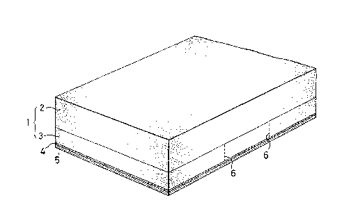
Fig. 1 is a schematic perspective view showing a
first el~bodiment of a heat transfer shee-t according to the
present inven-tion;
Fig. 2 is a schematic perspective view showlng a
state in which a second substrate and a thermally
transferable layer have been peeled off according to
shapes of letters from the heat transfer sheet shown in
Fig. 1;
Fig. 3 is a schematic perspective view showing a
second embodiment of a heat transfer sheet according to
the present invention;
Fig. ~ is a schematic perspective view showing a
state in which a second substrate, etc. have been peeled
off according to shapes of letters from the heat transfer
shee~ shown in Fig. 3;
Fig. 5 is a schematic perspective vlew showing a
third embodiment of a heat transfer sheet according to the
present lnvention;
Fig. 6 is a schematic perspective view showing a
fourth embodiment of a heat transfer sheet according to
the present invention; and
. ~.. ',, '
~ ~3 J'~
f;ig. / is a schematic cross-sectional view showing a
state :in which an e~)odimerlt of a heat transfer sheet
according to the present invention is placed on a transfer
-table of H.V.A. after peeling off a second substrate and a
thermally -transferable layer therefrom according to shapes
of letters, and in which the deaeration is performed prior
to heat transfer using -the H.V.A.
Embodiments of the present invention will be
descrlbed in de-tail below by reference to the accompanying
drawings.
mple 1
Fig. 1 shows the cross-section of a heat transfer
sheet having a therrnally transferable layer provided on a
couched base paper, as a first embodiment of the present-
invention.
A base paper 1 consisting of a first substrate 2 and
a second substrate 3 was obtained by couching two layers
each having a basis weight of 40 y/m2 using a multi-layers
cylinder paper machine so as to have appropriate peeling
properties. The base paper 1 has a basis weight of 80
g/m2, a Stockigt sizing degree of 20 seconds, and an air
resistance of 15 seconds. Each of the first and second
substrates 2 and 3 has a smoothness of 10 seconds. An
emulsion silicone (KM-768, Shin-Etsu Chemical Co., Ltd.)
was applied onto the second substrate 3 to a dry weight of
- 12 -
~ ~3 ~ ~3 ~
l g/m2 to form a releasincJ ~a~er 9. A pigmented resincornpris:LncJ an acryllc resin, a vinyl chloride-vinyl
aceta-te copolymer resin, and a pigment was applied onto
the releasing layer 4 to a dry weight of 5 to 10 g/m2 to
form a thermally transferahle layer 5, thereby completing
a heat -transfer sheet. The heat transfer sheet was
subjec-ted -to an action by a grid type automatic cutting
rnachine, whereby notches 6 extendlng from the thermally
transferable layer 5 to the interface between the second
substrate 3 and the first substra-te 2 were formed along
the letters "LINTEC" in a region measuring 1,000 mrn x
3,000 mm. Then, unnecessary portions of the thermally
transferable layer 5 were peeled off together with the
corresponding portions of the second substrate 3 along the
notches 6 for the letters "LlNTEC" (Fig. 2). The
thermally transferable layer containing the letters was
thermally transferred to a non-rigid polyvinyl chloride
cloth for tent (Lunashine #100, Teijin I.td.) in accordance
wi~h the aforementioned procedure using the H.V.A. The
time required for deaeration was 45 seconds, and the heat
transfer conditions were 110C., 600 mmHg (gauge
pressure), and 5 minutes. Notch formation by the
automatic cutting machine, the peeling properties of the
first substrate 2 and the second substrate 3 during the
removal of the unnecessary portions, and the transfer
properties of the thermally transferable layer containing
- 13 -
S3 ~
-the lette:cs were all exce]lent, ar,d thus a satisfactory
transferred p~l-ttern was ohtained.
E amp:l.e 2
A hea-t transfer sheet was prepared in the same manner
as ir-l Exarnple 1, excep-t tha-t a polyethylene .resin was
laminate-coated to a thickness of 30 ~m as releasing layer
4. The heat transfer sheet was subjected to an operation
by a grid type automatic cutting machine in the same way
as in Example 1 to make the cut-out letters "LINTEC". The
thermally transferable l.ayer containing the letters was
thermally transferred to a non-rigid polyvinyl chloride
cloth for tent (Lunashine #100) in accordance with the
procedure of Example 1 using the H.V.A. In the instant
embodimen-t, deaeration in the H.V.A. was completed in 43
seconds, the pressure reached was 600 mmHg (gauge
pressure), and heat was applied at 115C. for 5 minutes.
The transfer properties were satisfactory.
Example 3
Fig. 3 shows the cross-section of a heat transfer
sheet having a thermally transferable layer formed on an
laminated base paper, as a second embodiment according to
the present invention.
Woodfree paper having a basis weight of 110 g/m2, an
air resistance of 15 seconds, and a smoothness of 20 to 25
seconds was used as a first substrate 2. A polyethylene
- 14 -
2~ g8~
res1n was laminate-coa~:ed onto the first substra-te 2 to a
thickness of 17 ,~rn to serve as a barrier layer (not
shown). A solvent~based silicone resin (KS-833, Shin-Etsu
Chemical Co., Ltd.) was applied onto the polyethylene
layer to a solid weight of 0.5 g/m2 to form a peel layer
7. Woodfree paper having a ~asis weight of 70 g/m2, an
air resistance of 25 seconds, and a smoothness of 30 to 40
seconds serving as a second subs-trate 3 was laminate-
coated with a polyethylene resin to a coating thickness of
1~ 30 ~m to form a releasing layer 4. The same pigmented
resin composition as in Example 1 was applied onto the
releasing layer 4 to a dry weight of 5 to 10 g/m2 to form
a thermally transferable layer 5. The first substrate 2
and the second substrate 3 provided with the thermally
transferable layer 5 were laminated using a curable
adhesive 8 of an acrylate copolymer (Orivain BPS-4891,
Toyo Ink Mfg. Co., Ltd.) to obtain a heat transfer sheet.
The heat transfer sheet was subjected to an operation by a
grid type automatic cutting machine in the same way as in
Example 1 to make the cut-out letters "LINTEC" (Fig. 4~.
The thermally transferable layer containing the letters
was thermal]y transferred to a non-rigid polyvinyl
chloride cloth for tent ~Lunashine ~100) in the same
manner as in Example 1 using the H.V.A. The deaeration
time was 43 seconds, the pressure reached was 600 mmHg
(gauge pressure), and heat was applied at 110C. for 5
minutes. The cutting properties, the peeling properties
- 15 -
. ~3 ~`3~
of the ~Innecessary portiorls, and the transfer properties
were all e~xcellent.
~ les ~ to 7
Heat transfer shee-ts were prepared in the same way as
in Example 3, except that the ma-terials shown in Table 1
were used for the first substra-te.
The heat transfer sheets of Example ~ using crepe
paper and Example 5 using an extensible kraf-t paper can be
shown schematically, for example, as in Fig. 5. The heat
transfer sheet o:E Example 6 using embossed paper can be
shown schematically, for example, as in Fig. 6.
- 16 -
~ Q`~
Table 1.
_
It_n_ __ Ex. 4 Ex 5 Ex. 6 Ex. 7
MaterialCrepe Extensible Embossed Nonwoven
paper kraft paper fabric
. _ paper _ ~
Basis weight 80 73 115 60
2.) _ ~ . _
Air
Resistance3 23 2,000 0
(seconds)
_ _
Smoothne s s
Front(se~.) 0 8 2 0
Back (sec.) 0 14 5 0
_
Nature of Air per- Slightly Poor air High air
material permeable air perrneabili perme-
rough permeable, -ty, rough ability,
surface slightly surface cloth-like
rough
_ _ _ surface _ _ _
Barrier for PE PE PE PE
17~m _ 17~m _ 17~lm 17~m
Peel same as same as same as same as
trea-tmen-t in Ex. 3 in Ex. 3 in Ex 3 in Ex 3
_._ _ __ _ . _ __
Deaeration 30 45 45 30
time(sec.)
_ ,.~_ _ _ ~_
Pressure
reached(gauge 600 mmHq600 mmHq 500 mmHq 600 mmHq
pressure)
,_ ~_
Heating 110C x 110C x llO C X 110C X
conditions 5 min. _ 5 min. ___ 5 min._ 5 min.
The resultlng heat transfer shee-ts (Examples 4
through 7) were all excellen-t ln sui-tablllty for cutting,
- 17 -
~J,~
the pe~incJ prc)perties of th~- unnecessary por-tions of the
thermally transferable layer, including the second
substratef as well as in the ease of deaera-tion and heat
transfer pLoperties in the H.V.A.
Nex-t, ~he deaeration action during the heat transfer
operation for -the heat -transfer sheet of the present
invention using the H.V.A. will be described with
reference -to Fig. 7. In this drawing, the reference
numeral 9 denotes a -transfer substance. The transfer
subs-tance 9 is placed on a -transfer table 10 of the
H.V.A., and a heat transfer sheet of the construction
il]ustrated in Fig. 1 is placed thereon with a thermally
transferable layer 5 facing downward. The hea-t transfer
sheet is covered with a framed rubber sheet 11, whereafter
air exis-ting between the transfer table 10 and the rubber
sheet 11 is removed by a vacuum pump (not shown). Since
the first substrate 2 of the heat transfer sheet is highly
air permeable, that air moves in the directions of arrows
in Fig. 7 and discharges to the surroundings of the heat
transfer sheet. The movement of air, i.e., deaeration, is
performed uniformly and rapidly throughout the heat
transfer sheet. Thus, no wrinkles are formed on the heat
transfer sheet, and no air reservoir remains between the
heat transfer sheet and the rubber sheet. This deaeration
action permits the rubber sheet to conform to the shape of
the heat transfer sheet, enabling heat transfer. Heating
~3{1~3s3?i~3
by a heatinc3 device (not shown) results in heat transfer
onto -the -transfer substance 9.
As described above, the heat transfer sheet of the
present inven-tion uses the firs-t substrate having a rough
surface and/or comprising an air permeable material.
Thus, -the hea-t transfer sheet exhibits satisfactory
deaeration and heat transfer properties, without the need
to use a porous material as a third material which has
been necessary with conven-tional heat transfer sheets.
Consequently, when the hea-t transfer sheet of the present
invention is subjected to heat transfer using the H.V.A.,
it is not necessary to cover the heat transfer sheet with
a porous material as a third material, thus making it
possible to increase the operating efficiency markedly.
Furthermore, the heat transfer sheet of the present
invention has the first substrate and the second
substrate. Hence, even if the thermally transferable
layer is thin, desired le-tters, symbols or designs can be
prepared easily by use of an automatic cutting system.
Therefore, the use of the heat transfer sheet according to
the present invention makes the printing of designs
unnecessary, and enables arbitrary designs to be prepared
whenever necessary and obtained as a heat transferred
pattern.
The present invention has been described in detail
with respect to preferred embodimen-ts, and it will now be
that changes and modifications may be made without
- 19 -
`3 ~
departlng :frc~irl ~he invention in its broader aspects, and
it is tne intention, therefore, in the appended claims to
cover all such changes arld modifications as fall within
the true spirit of the invention.
- 20 -