Sélection de la langue

Search

Sommaire du brevet 2099186 

Énoncé de désistement de responsabilité concernant l'information provenant de tiers

Une partie des informations de ce site Web a été fournie par des sources externes. Le gouvernement du Canada n'assume aucune responsabilité concernant la précision, l'actualité ou la fiabilité des informations fournies par les sources externes. Les utilisateurs qui désirent employer cette information devraient consulter directement la source des informations. Le contenu fourni par les sources externes n'est pas assujetti aux exigences sur les langues officielles, la protection des renseignements personnels et l'accessibilité.

Disponibilité de l'Abrégé et des Revendications

L'apparition de différences dans le texte et l'image des Revendications et de l'Abrégé dépend du moment auquel le document est publié. Les textes des Revendications et de l'Abrégé sont affichés :

  • lorsque la demande peut être examinée par le public;
  • lorsque le brevet est émis (délivrance).
(12) Demande de brevet: (11) CA 2099186
(54) Titre français: PLAQUE DE FIXATION SUR BATI-SUPPORT
(54) Titre anglais: ATTACHMENT PLATE ON A SUPPORTING FRAME
Statut: Réputée abandonnée et au-delà du délai pour le rétablissement - en attente de la réponse à l’avis de communication rejetée
Données bibliographiques
(51) Classification internationale des brevets (CIB):
  • E06B 1/02 (2006.01)
  • E03C 1/01 (2006.01)
  • E04C 2/52 (2006.01)
(72) Inventeurs :
  • WARKUS, CLEMENS (Allemagne)
  • VOGEL, THOMAS (Allemagne)
(73) Titulaires :
  • GEBERIT TECHNIK AG
(71) Demandeurs :
  • GEBERIT TECHNIK AG (Suisse)
(74) Agent: SMART & BIGGAR LP
(74) Co-agent:
(45) Délivré:
(22) Date de dépôt: 1993-06-25
(41) Mise à la disponibilité du public: 1994-01-17
Requête d'examen: 2000-03-14
Licence disponible: S.O.
Cédé au domaine public: S.O.
(25) Langue des documents déposés: Anglais

Traité de coopération en matière de brevets (PCT): Non

(30) Données de priorité de la demande:
Numéro de la demande Pays / territoire Date
2245/92-6 (Suisse) 1992-07-16

Abrégés

Abrégé anglais


ATTACHMENT PLATE ON A SUPPORTING FRAME
ABSTRACT OF THE DISCLOSURE
The attachment plate has laterally several openings (4) which
each extend along an edge (9) and around it. The openings (4)
serve in each instance the purpose of inserting a rotary snap-in
connector (15) which has a handle (17) and a head (16) formed on
it. The head (16) is so shaped as to correspond to a dovetail
groove (11) of a profile rod (10) and is snapped into it. A
snapping lug (7) engages form-fittingly with a channel (12) of a
contour of the rods (10). The rotary snap-in connectors (15) can
be set in without tools, are latchable and permit an independent
mounting of the attachment plate (1) on a supporting frame having
profile rods (10).

Revendications

Note : Les revendications sont présentées dans la langue officielle dans laquelle elles ont été soumises.


THE EMBODIMENTS OF THE INVENTION IN WHICH AN EXCLUSIVE
PROPERTY OR PRIVILEGE IS CLAIMED ARE DEFINED AS FOLLOWS:
1. An attachment plate (1) particularly for mounting sanitary
connection lines, a frame (13) supporting said attachment
plate, means (15) for detachably connecting said attachment
plate (1) to said frame, said frame having profile rods (10),
said means (15) being rotary snap-in connectors, said
attachment plate having lateral recesses (4), each of said
profile rods (10) having 8 groove (11), each of-said rotary
snap-in connectors snapping into said grooves (11) after
having been introduced into said lateral recesses.
2. The attachment plate according to claim 1, wherein said
attachment plate has side portions (5, 6) rearwardly bent,
said side portions having an opening (4b), said rotary snap-in
connectors having a head (16), said head being inserted
through said opening.
3. The attachment plate according to claim 1, wherein said
attachment plate (1) has an opening (4a) at the front face
thereof and said rotary snap-in connectors (15) are inserted
from the rear of said plate (1) through said opening.
4. The attachment plate according to claim 2, wherein said side

portions (5, 6) have projecting lugs (7), said lugs being
inserted into said grooves (11) of said profile rod (10) for
centering and for load transfer of said attachment plate (1).
5. The attachment plate according to claim 1, wherein said
profile rods (10) have a contour at the bottom of said
grooves.
6. The attachment plate according to claim 5, wherein said
contours are channels (12) extending transversely.
7. The attachment plate according to claim 2, wherein said
rotary snap-in connectors (15) have each a formed-on head
(16), said head being snapped by twisting into a groove (11)
of a profile rod (10).
8. The attachment plate according to claim 7, wherein said head
has a projection (16b), said projection being snapped into a
contour of said groove (11).
9. The attachment plate according to claim 8, wherein said head
has a front face and said projection (16b) is formed on said
front face of said head (16).
10. The attachment plate according to claim 1, wherein each of

said rotary snap-in connectors (15) have a lobe-form handle
(17).

Description

Note : Les descriptions sont présentées dans la langue officielle dans laquelle elles ont été soumises.

2~9~18~
The present invention rela~es to an attachment plate on a
supporting frsme, in particular for mounting sanitary connection
lines with means which detachably connect the attachment plate with
the profile rods of the supporting frame.
BACKGROUND OF THE INVENTION
A fixture plate is known which is mounted by means of screws
on rectangular tubes of a supporting frame and which has several
openings disposed st a given distance one from the other and which
are provided for mounting fixtures and their connection lines9 in
particular for the hot and cold water connection. With an
attachment plate of this type of 8 supporting frame a comparatively
simple mounting of fixtures fronting the wall is possible~ However
mounting the fixture plate on the supporting frame is comparatively
expensive in labor.
SUMMARY OF THE I~VENTION
An object of the present invention is to provide an attachment
plate of the stated type which may be mounted significantly more
easily and which nevertheless meets sanitary requirements.
This object is achieved by providing the stated means as
.
. ~ :
,

20991~
rotary snap-in connector3 which go through a lateral reces~ of the
attachment plate and snsp into 8 longitudinal groove of a profile
rod. Through the snapping of the rotary snap-in connector into a
longitudinal groove of a profile rod a form-fit connection between
the rotary snap-in connector snd the profile rod may be obtained
which effectively prevents a displacement of the rotary snap-in
connectors slong the profile rod. In view of the fact ~hat since
the rotary snap-in connectors may be set in and snapped in at any
site in the longitudinal groove, 8 stepless mounting of the
attachment plate on the supporting frame is possible. The
adjustment and alignment of the attachment plate consequently is
significantly simpler than sccording to the known attachment pla~e.
For mounting the attachment pla~e on the supporting frame no tools
are required, a fact which significantly simplifies the mounting
step.
It has also been found that these rotary snap-in connectors
can be produced very cost-effectively and yet are durable and
robust in the form of injection molded parts made of synthetic
material. They may also be fabricated in diecasting processes.
Another advantage is that few individual parts are required so
that, lastly, an attachment plate on a supporting frame is provided
which evidently is made with relatively few simple structural
parts, and which meets no~ only the technical sanitary requirements
extremely well but which, due to its simple implementation, is
moreover favorable in terms of cost and is reliable.
` ' : ' . ,
,
.
; ~ . . ~ . .

2 ~
BRIEF DESCRIPTION OF THE DRAWINGS
Further advantageous features are described in the following
specification, the dependent claims as well as the drawings. An
example of the invention will be explained in greater de~ail in
con~unction with the drawings of which:
Fig. 1 is a perspective partial view of an attachment plate on a
supporting frame according to the invention;
Fig. 2 is a schematic perspective partial view of an attachment
plate on a supporting frame with sanitary objects mounted
thereon;
Fig. 3 illustrates an attachment plate;
Fig. 4 and 5 are perspective view~ of a portion of an attachment
plate on a supporting frame;
Fig. 6 is a perspective partial view of an attachment plate; and
Fig~ 7 is a view of a rotary snap-in connector.
DESCRIPTION OF THE PREFERRED EMBODIMENT
Fig, 2 shows schematically a supporting frame 13 which has a
three-dimensional structure and which is mounted on a housing wall
19 and floor 20. An attachment plate 1 made of sheet metal with
connection openings 3 is mounted on vertical profile rods lOa and a
horizontal profile rod lOb. Transverse profile rods lOc of the
-
.

20~91~
stated profile rods are connected with further profile rod~ lOddisposed in parallel behind them.
To the attachment plate 1 are mounted wa~er connec~ion lines
18 for a water fixture 21 on a wsshstand 14. The washstand 14 is
mounted with bolts, no~ shown here, in known manner on profile rods
lOa. The water connection lines 18 are fastened in known manner to
openings 3 of ~he attachment plate 1, and water pipes 18 are
connected with the fixture 21 through the opening 3. As can be
seen, the front face of the attachment plate 1 is flush with the
front face of the profile rods lOa and lOb.
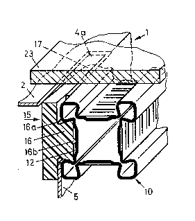
As shown in Fig. 1, the attachmen~ plate 1 is implemented so
as to be box-form and has a planar rec~angular front face 2 as well
as side portions 5 and 6 a~ a right sngle. The front face has the
above stated connection opening~ 3 which, as shown, may be
circular. For mounting the ~ttachment plate 1 on profile rods 10
the attachment plate 1 has several openings 4 which extend along
the bent edges 9 and around them~ These openings 4 comprise in
each instance a slot 4a disposed at the front face for inserting a
rotary snap-in connector 15. The slot 4a is connected in each
instance with a slot 4b extending transversely to i~, and which
extends in a ~ide por~ion 5 or 6 and through which the he~d 16 of a
rotary snap-in connector 15 can be set into a groove 11 of a
profile rod 10. The attachment plate 1 shown here comprises at the
side portions 6 two openings 4 each and at the shorter side
portions 5 one opening 4 each. The sttachment plate 1 consequently
.
.

2~9~
can be connected on all sides with a profile rod 10. However it iQ
also possible to connect the attschment plate l only on two side
portions 5 or 6, respectively, with profile rods 10.
The profile rods 10 are hollow rectangular tubes and have on
each side a dovetail groove 11 extending in the longitudinal
direction. The groove bottoms of the profile rods 10 are contoured
in each instance by meanQ of transversely extending channels 12.
The function of these channels 12 will be explained hereinbelow in
greater detail in conjunction with Figs. 4 to 7.
The rotary snap-in connector 15 shown in these Figures is made
integrally of a suitable synthetic material as an injection molded
part and has a lobe-form handle 17 onto which is formed a laterally
projecting head 16. This he~d 16 is implemented so 8S to
correspond ~o the grooves 11 and hss laterally opposing undercuts
16a and on the front face a projecting bump 16b. The undercuts 16a
change over opposingly into bent guide surfaces 16c. The distance
of opposing guide surfaces 16c is equal to or smaller than the
smallest width of a dovetail groove 11. In order to ~onnect an
attachment plate 1 with a profile rod 10, a side portion 5 or 6 is
placed with its surface on a profile rod 10 and as shown in Fig. 4,
the front face 2 is flush with one side of the profile rod 10.
Through a slot 4a of an opening 4 or from the rear side of the
plate 1 a rotary snap-in connector 15 is inserted into the
attachment plate 1 and the head 16 through the slot 14b into a
groove 11. As shown in Fig. 4, handle 17 then projects at the
.
-:

20991~
front face on the attachment plate 1. When the rotary snsp-in
connector lS is rota~ed by its handle by 90 in the direction of
the arrow 21, the rotary snap-in connector 15 rotates about a
swivelling axis 22 extending through the bumps 16b. Through this
swivel motion the handle 17 is lowered by the slot 4a behind the
front face 2 and the head 16 is clamped in a dovetail groove 11
through the laterally adjoining undercuts 16a and through the bump
16b engaging a channel 12 and snaps in. The snap-in connection is
consequently closable from the front. The laterally adjacent
undercuts 16a prevent a motion of the rotary snap-in connectors 15
transversely to the profile rod 10 and the bumps 16b prevent a
motion of the rotary snap-in connector 15 in the longitudinal
direction of the profile rod 10. The snapped-in position of the
rotary snap-in connector 15 is shown in Fig. 5. Longitudinal
displacement of the attachment plate 1 is the longitudinal
direction of the profile rod 10 i-~ also impossible since the side
portion 5 on the slot 4b is bilaterally adjacent on the head 16
and, moreover, the surface of the ~ide portion 5 is clamped between
the handle 17 and the profile rod 10. The attachment plate 1 is
consequently in both longitudinal directions of the profile rod 10
and in one transverse direction form-fit and force-fit to the
profile rod 10.
: It is evident that the rotary snap-in connector 15 csn be
inserted into the opening 4 without tools and can be snapped into
the groove 11. It is just as simple to detach again the rotary
. ~ :

2~31g&
snap-in connector 15, for example for adjustments.
A planking plate 23 shown in Fig. 5 applied subsequently
prevents an unwanted swivelling of the connector 15 and
consequently prevents detachment of the snap-in connection.
As shown in Fig. 1, the side portion 5 and 6 have each two
projecting lugs 7 which engage a groove 11 of a profile rod 10
placed against them and these lugs 7 are esse~tially as wide as a
groove 11. Therefore it is ensured that an attachment plate 1
mounted on a supporting frame 13 st its front face is flush with
the adjacent profile rods 10. ~owever, the attachment plste 1 is
not only flush at the front face but rather also has no projecting
parts which would hinder mounting a fixture or a sanitary object.
The lugs 7, in addition, secure the attachment plate 1 against
twisting and this explains the fact that, as a rule, in each
instance one rotsry snap-in connector 15 on one plate side is
sufficient.
As a rule, the attachment pla~e 1 shown in Fig. 1 is mounted
on both side portions 5. The plate can simultaneously also be
mounted on horizon~al profile rods 10. It is understood that it is
also possible to mount the plate 1 rotated by 90 on a supporting
frame 13.
- . : , -' ~ ':
. ~
.
, . ,

Dessin représentatif
Une figure unique qui représente un dessin illustrant l'invention.
États administratifs

2024-08-01 : Dans le cadre de la transition vers les Brevets de nouvelle génération (BNG), la base de données sur les brevets canadiens (BDBC) contient désormais un Historique d'événement plus détaillé, qui reproduit le Journal des événements de notre nouvelle solution interne.

Veuillez noter que les événements débutant par « Inactive : » se réfèrent à des événements qui ne sont plus utilisés dans notre nouvelle solution interne.

Pour une meilleure compréhension de l'état de la demande ou brevet qui figure sur cette page, la rubrique Mise en garde , et les descriptions de Brevet , Historique d'événement , Taxes périodiques et Historique des paiements devraient être consultées.

Historique d'événement

Description Date
Inactive : CIB de MCD 2006-03-11
Demande non rétablie avant l'échéance 2003-06-25
Le délai pour l'annulation est expiré 2003-06-25
Inactive : Abandon. - Aucune rép dem par.30(2) Règles 2002-07-03
Réputée abandonnée - omission de répondre à un avis sur les taxes pour le maintien en état 2002-06-25
Inactive : Dem. de l'examinateur par.30(2) Règles 2002-01-03
Lettre envoyée 2000-03-28
Inactive : Dem. traitée sur TS dès date d'ent. journal 2000-03-28
Inactive : Renseign. sur l'état - Complets dès date d'ent. journ. 2000-03-28
Exigences pour une requête d'examen - jugée conforme 2000-03-14
Toutes les exigences pour l'examen - jugée conforme 2000-03-14
Lettre envoyée 1997-12-08
Lettre envoyée 1997-12-05
Demande publiée (accessible au public) 1994-01-17

Historique d'abandonnement

Date d'abandonnement Raison Date de rétablissement
2002-06-25

Taxes périodiques

Le dernier paiement a été reçu le 2001-06-21

Avis : Si le paiement en totalité n'a pas été reçu au plus tard à la date indiquée, une taxe supplémentaire peut être imposée, soit une des taxes suivantes :

  • taxe de rétablissement ;
  • taxe pour paiement en souffrance ; ou
  • taxe additionnelle pour le renversement d'une péremption réputée.

Les taxes sur les brevets sont ajustées au 1er janvier de chaque année. Les montants ci-dessus sont les montants actuels s'ils sont reçus au plus tard le 31 décembre de l'année en cours.
Veuillez vous référer à la page web des taxes sur les brevets de l'OPIC pour voir tous les montants actuels des taxes.

Historique des taxes

Type de taxes Anniversaire Échéance Date payée
Enregistrement d'un document 1997-06-10
TM (demande, 4e anniv.) - générale 04 1997-06-25 1997-06-24
TM (demande, 5e anniv.) - générale 05 1998-06-25 1998-04-14
TM (demande, 6e anniv.) - générale 06 1999-06-25 1999-06-21
Requête d'examen - générale 2000-03-14
TM (demande, 7e anniv.) - générale 07 2000-06-27 2000-06-20
TM (demande, 8e anniv.) - générale 08 2001-06-26 2001-06-21
Titulaires au dossier

Les titulaires actuels et antérieures au dossier sont affichés en ordre alphabétique.

Titulaires actuels au dossier
GEBERIT TECHNIK AG
Titulaires antérieures au dossier
CLEMENS WARKUS
THOMAS VOGEL
Les propriétaires antérieurs qui ne figurent pas dans la liste des « Propriétaires au dossier » apparaîtront dans d'autres documents au dossier.
Documents

Pour visionner les fichiers sélectionnés, entrer le code reCAPTCHA :


Pour visualiser une image, cliquer sur un lien dans la colonne description du document. Pour télécharger l'image (les images), cliquer l'une ou plusieurs cases à cocher dans la première colonne et ensuite cliquer sur le bouton "Télécharger sélection en format PDF (archive Zip)" ou le bouton "Télécharger sélection (en un fichier PDF fusionné)".

Liste des documents de brevet publiés et non publiés sur la BDBC .

Si vous avez des difficultés à accéder au contenu, veuillez communiquer avec le Centre de services à la clientèle au 1-866-997-1936, ou envoyer un courriel au Centre de service à la clientèle de l'OPIC.


Description du
Document 
Date
(aaaa-mm-jj) 
Nombre de pages   Taille de l'image (Ko) 
Dessin représentatif 1998-08-24 1 13
Abrégé 1994-03-11 1 20
Revendications 1994-03-11 3 61
Dessins 1994-03-11 2 64
Description 1994-03-11 7 227
Rappel - requête d'examen 2000-02-27 1 119
Accusé de réception de la requête d'examen 2000-03-27 1 178
Courtoisie - Lettre d'abandon (taxe de maintien en état) 2002-07-22 1 183
Courtoisie - Lettre d'abandon (R30(2)) 2002-09-10 1 170
Taxes 1999-06-20 1 48
Taxes 2001-06-20 1 33
Taxes 2000-06-19 1 31
Taxes 1997-06-23 1 52
Taxes 1998-04-13 1 54
Taxes 1996-06-20 1 48
Taxes 1995-06-21 1 49