Note : Les descriptions sont présentées dans la langue officielle dans laquelle elles ont été soumises.
CA 02099710 2004-02-12
EXHAUST SYSTEM FOR A TURBOMACHINE
BACKGROUND OF THE INVENTION
The present invention relates to an exhaust system for a turbomachine,
such as a steam or gas turbine or the like. More specifically, the present
invention
relates to an exhaust system for an axial flow turbomachine that minimizes the
strength of harmful vortices within the flow.
The performance of a steam turbine may generally be improved by
lowering the back pressure to which the last row of blades of the turbine is
subjected. Consequently, turbines often discharge to a condenser in which a
sub-
atmospheric pressure is maintained. Typically, the exhaust steam discharging
axially from the last row of blades is directed to a condenser mounted below
the
turbine by turning the flow 90° from the axial to the vertically
downward
directions. This turning of the flow is accomplished by an exhaust system that
includes a diffuser in flow communication with an exhaust housing.
Diffusers are generally comprised of inner and outer flow guides that
serve to increase the static pressure by reducing the velocity head.
Typically, the
cross-sectional shape of the outer flow guide is a simple arcuate shape --
see, for
example, U.S. Patent Nos. 3,945,760; 4,863,341; 3,058,720; 3,697,191; and
3,690,786. However, conical shaped diffusers have also been utilized - see,
for
example, U.S. Patent No. 4,391,566. Although outer flow guides are generally
of
uniform axial length, at least one steam turbine manufacturer has utilized an
outer
flow guide in a bottom exhaust system that has an axial length that varies
around
its
' CA 02099710 2004-02-12
2
circumference, being a maximum at the bottom of the diffuser
and a minimum at the top.
The exhaust housing receives steam from the diffuser
and directs it to the condenser through a bottom outlet
opening in the housing. To obtain maximum performance, it is
important to configure the exhaust system so as to minimize
losses arising from the formation of vortices in the steam
flow. However, as explained below, the difficulty of this
task is exacerbated by the somewhat torturous path the steam
must take as it is directed to the condenser.
The steam from the diffuser enters the exhaust
housing in a 360° arc. However, it discharges from the
exhaust housing to the condenser through only the bottom
outlet opening_ This presents no problem with respect to the
steam flowing in the bottom portion of the diffuser since by
turning such steam into the radial direction, the diffuser
turns the steam directly toward the bottom outlet opening.
However, the steam discharging at the top of the diffuser must
turn 180° from the vertically upward direction to the
vertically downward direction, in addition to turning 90° from
the axial direction to the vertically upward direction.
Consequently, vortices are formed within the exhaust housing
in the vicinity of the top of the diffuser outlet that create
losses in the steam flow that detract from the efficiency of
the exhaust system and, therefore, the performance of the
turbine.
One approach for minimizing such losses used in the
past involves the incorporation of flow dividers into the
exhaust diffuser that allow the steam to expand and turn into
the radial direction through several smaller concentric flow
passages, rather than a single large flow passage, as
disclosed in U.S. Patent No_ 3,149,470 (Herzog). Another
approach, suggested for a gas turbine exhaust system, involves
the use of flow stabilizing ribs formed on the outer diameter
of the diffuser that guide the flow toward the outlet opening
so as to prevent the formation of vortices, as disclosed in
U.S. Patent No. 4,391,566 (Takamura). However, such
CA 02099710 2004-02-12
3
approaches have not been entirely successful and can result
in a considerable increase in the manufacturing cost of the
diffuser.
It is therefore desirable to provide an exhaust
system for a turbomachine capable of turning an axial flow
discharging from the turbine into a radial direction, such as
vertically downward, in such a way that the formation of
vortices and other loss mechanisms are minimized. It is also
desirable that the shape of the exhaust diffuser in such an
exhaust system facilitate its manufacture, thereby minimizing
the cost of the diffuser.
SUMMARY OF THE INVENTION
Accordingly, it is the general object of the current
invention to provide an exhaust system for a turbomachine
capable of turning an axial flow discharging from the turbine
into a direction perpendicular to the axial direction, such
as vertically downward, in such a way that the formation of
vortices and other loss mechanisms are minimized_
Briefly, this object, as well as other objects of
the current invention, is accomplished in a turbomachine
''comprising (i) a turbine cylinder forming a flow path far a
working fluid, (ii) an exhaust conduit for directing the
working fluid away from the turbine cylinder, and (iii) an
exhaust diffuser for directing the flow of the working fluid
from the turbine cylinder to the exhaust conduit. According
' to the current invention, the exhaust diffuser has (i) an
inner flow guide, (iij an outer flow guide having an outlet
defining an axial length of the outer flow guide, the axial
length varying around the periphery of the flow guide and
being a minimum at a predetermined location on the periphery,
and (iiij a substantially radially extending member disposed
axially a predetermined distance from the outlet at the
predetermined location.
In one embodiment of the current invention, the
cylinder discharges the working fluid in a substantially axial
direction and the flow path formed by the exhaust conduit
discharges the working fluid in a direction substantially
~
CA 02099710 2004-02-12
4
perpendicular to the axial direction. The exhaust diffuser
turns the direction of flow of the working fluid approximately
90°. The exhaust conduit has an inlet in which the outer flow
guide outlet is disposed and an outlet formed in only a
portion of its periphery, whereby in a first portion of the
outer f low guide its outlet is proximate the exhaust conduit
outlet and in a second portion of the outer f low guide its
outlet is remote from the exhaust conduit outlet. The axial
length of the outer flow guide varies around its periphery,
the axial length of the outer flow guide being at a maximum
value in its first portion and a minimum value in its second
portion.
BRIEF DESCRIPTION OF THE DRAWINGS
Figure 1 is a longitudinal cross-section through a
portion of a low pressure steam turbine incorporating the
exhaust system according to the current invention.
Figure 2 is an isometric view of the exhaust system
shown in Figure 1.
Figure 3 is a cross-section taken through line III-
III shown in Figure 1_
Figure 4 is a longitudinal cross-section of a
preferred shape of the outer flow guide according to the
current invention.
Figure 5 is a view similar to Figure 3 showing the
shape of the outlet of the outer flow guide according to an
alternate embodiment of the current invention projected onto
a plane normal to the turbine axis.
DESCRIPTION OF THE PREFERRED EMBODIMENT
There is shown in Figure 1 a longitudinal cross
section of the right half of a low pressure steam turbine 1
with a downward exhaust. The primary components of the steam
turbine are an outer cylinder 2, an inner cylinder 3 enclosed
by the outer cylinder, a centrally disposed rotor 4 enclosed
by the inner cylinder and an exhaust system 10. The inner
cylinder 3 and rotor 4 form an annular steam flow path
therebetween, the inner cylinder forming the outer periphery
of the flow path. A plurality of stationary vanes 5 and
CA 02099710 2004-02-12
rotating blades, each of which has an airfoil portion, are arranged in
alternating rows and extend
into the steam flow path. The vanes 5 are affixed to the inner cylinder 3 and
the blades are
affixed to the periphery of the rotor 4.
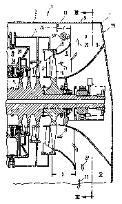
As shown in Figures 1 and 2, the exhaust system 10 is comprised ofan exhaust
housing 7 formed by an end wall 29 connected to a horseshoe-shaped rim 31. An
outlet 32 is
formed in the bottom of the exhaust housing 7 and is connected to a condenser
(not shown). An
exhaust diffuser is disposed within the exhaust housing 7. The exhaust
diffuser is formed by
inner and outer approximately frusto-conical members 8 and 9, respectively,
referred to as flow
guides. The inner and outer flow guides 8 and 9 form a substantially annular
diffusing passage
therebetween. The airfoil portions 6 of the blades in the last row of blades -
that is, in the row
that is farthest downstream - are disposed just upstream of the outer flow
guide 9. The outer
flow guide 9 is attached via a flange 18 to the inner cylinder 3.
As shown in Figure 3, the exhaust housing 7 forms the outer boundary for an
approximately horseshow-shaped chamber 1 I . The inner boundary of the chamber
1 1 is formed
by the outer flow guide 9.
As shown in Figure 1, steam 20 enters the steam turbine I from an annular
chamber 34 in the outer cylinder 2. The steam flow is then split into two
streams, each flowing
axially outward from the center of the steam turbine through the
aforementioned steam flow
path, thereby imparting energy to the rotating blades. The steam 21 discharges
axially from the
last row of blades 6 and enters the exhaust diffuser. The exhaust diffuser
guides the steam 21
into the exhaust housing 7 over a 360° arc. Due to the curvature of its
inner surfaces, the diffuser
turns the steam 21 approximately 90° into a substantially radial flow
of steam 22 entering the
chamber 1 I . The chamber 11 directs the steam 22 to the exhaust housing
outlet 32.
As shown in Figure 3, at the bottom of the chamber I 1 the radially flowing
steam
22 exiting the diffuser merely
~
CA 02099710 2004-02-12
continues to flow radially downward through the outlet 32.
However, at the top of the chamber 11 -- that is, at the apex
of the horseshoe shape -- the steam 22 is discharged in the
vertically upward direction by the exhaust diffuser and must
turn an additional 180° around the horseshoe-shape to flow
vertically downward through the opening 32. As a result of
these large and relatively abx-upt changes in steam flow
direction, a vortex 30 is formed in the steam flow within the
chamber just behind the outlet 12 of the outer flow guide 9.
As shown in Figure 3, the vortex 30 extends around the chamber
11 in a horseshoe-shape and increases the aerodynamic losses
of the exhaust system 10, thereby detracting from the turbine
performance.
According to the current invention, the strength of
this vortex and, therefore, its ability to affect the losses,
is minimized by the novel exhaust system of the current
invention. Specifically, as shown in Figure 4, although the
flow guide inlet 13 lies in a plane that is oriented
perpendicularly to the axis 33 of the turbine, the outlet 12
lies in a plane that is oriented at an angle A to a plane
perpendicular to the turbine axis. In the preferred
embodiment, the angle A is approximately 3°. The plane in
which the flow guide outlet 12 lies has been rotated counter
clockwise, when viewed as in Figure 1, from the perpendicular
about a horizontal axis so that the top of the outlet is
' disposed upstream of the bottom of the outlet. As a result,
the axial length X of the outer flow guide 9, shown in Figure
1, varies linearly around its circumference and is at a
minimum value at the top of the flow guide, remote from the
exhaust housing outlet 32, and is at a maximum value at the
bottom of the f low guide, proximate the exhaust housing outlet
32.
As shown in Figure 1, a baffle 28, affixed to the
top of the housing 7, extends radially inward into the chamber
11 at its apex. According to the current invention, the
aforementioned variation iii the outer flow guide 9 axial
length, together with the baffle 28, ameliorates the effect
CA 02099710 2004-02-12
7
of the vortex 30. Specifically, because of the shortened length of the outer
flow guide 9 at its
top, the steam flow 21 exits at the top of the diffuser closer to the baffle
28 than it otherwise
would, as shown in Figure 1. As a result, the vortex 30 is somewhat "crowded"
against the
baffle 28. This "crowding" of the vortex 30 has the salutary effect of
reducing its strength. The
desired distance Y, shown in Figure 1, from the outlet I 2 of the outer flow
guide 9 to the baffle
28 at the top of the diffuser to ensure sufficient "crowding" of the vortex is
a function.of the
length of the airfoil 6 of the blades in the last row of rotating blades. In
the preferred
embodiment, the axial distance Y from the outlet 12 of the outer flow guide 9
to the baffle 28 at
the top of the diffuser - that is, at a location 180° from the exhaust
housing outlet 32 = is about
one half of the length of the airfoil 6, as shown in Figure 1. In the
embodiment shown in Figure
1, the length of the airfoil portions 6 of the last row of blades is
approximately 119 cm (47
inches. Note that the outer flow guide 9 shape and the baffle 28 allows the
vortex to be crowded
without excessive shortening of the outer flow guide.
In the embodiment of the invention discussed above, the minimum axial length
of
the outer flow guide 9 is at top dead center and the maximum axial length is
at bottom dead
center. Thus, the flow guide outlet 12 can be considered as having been
rotated about a
horizontal axis so that it maintains its symmetry about a vertical axis - that
is, if the circular
outlet 12 were projected onto a vertical plane - for example, as viewed in
Figure 3 - it appears as
an ellipse having a major axis that is horizontally oriented and a minor axis
that is vertically
oriented. However, in some turbine designs, the amount of swirl in the steam
flow 21 exiting the
last row turbine blades will make it advantageous to skew the outlet 12 so
that minimum and
maximum axial lengths are rotated off of top and bottom dead center. As a
result the flow guide
outlet 12' will no longer be symmetric about the vertical axis and, when
projected in a vertical
plane, the major and minor axes will be rotated by
' CA 02099710 2004-02-12
8
an angle B with respect to the horizontal and vertical
directions, as shown in Figure 5.
According to an important aspect of the current
invention, the outer flow guide 9 is shaped so that the flow
guiding inner surface adjacent its outlet edge 14 is oriented
substantially radially, as shown in Figure 4,. As a result,
the flow guide fully turns the steam flow into the radial
direction. Using the flow guide to fully turn the steam flow
from the axial to the radial direction has the salutary effect
of reducing the aerodynamic losses in the diffuser.
Unfortunately, combining this complete radial
turning feature with the aforementioned varying axial length
feature considerably complicates the manufacture of the outer
flow guide if the simple arcuate cross-sectional shape
heretofore used in the art were retained. This is so because
with a simple arcuate shape, the cross-sectional radius of
curvature of outer flow guide would have to vary continuously
around its circumference in order to maintain the orientation
of the inner surface adjacent the outlet edge 14 in the radial
direction over the full 360° arc of the outer flow guide
outlet 12. If the radial orientation of this inner surface
were not maintained, the aforementioned benefit of using the
outer flow guide to fully turn the flow would be compromised.
However, varying the radius of curvature around the
circumference so as to maintain the radial orientation of the
inner surface adjacent the outlet edge 14 would require a
complex and expensive die for forming the flow, guide if a
simple arcuate shaped cross-section were used.
According to the current invention, this
manufacturing problem is overcome, without sacrificing
performance, by utilizing the novel outer flow guide shape
shown in Figure 4. Specifically, the shape of the outer flow
guide 9 is characterized by a compound conical/arcuate shape
- that is, a straight conical section 16 is utilized to
connect inlet and outlet arcuate sections 15 and 17,
respectively_
CA 02099710 2004-02-12
9
As shown in Figure 4,.the inlet arcuate section 15
is symmetrical about the turbine axis 33 so that its radius
of curvature R remains constant around the circumference of
the outer flow guide 9. The outlet arcuate section 17 is also
symmetric except that its axis of symmetry has been tilted at
the aforementioned angle A. In addition, its radius of
curvature R' is_ also constant around the circumference of the
flow guide_ in the preferred embodiment, R is approximately
equal to R'. The outlet 12 of the flow guide has been
oriented at angle A by varying the length L of the conical
section ~16 _
The novel shape of the flow guide shown in Figure
4 considerably simplifies its manufacture because, although
the axial length of the flow guide varies constantly about its
circumference and the orientation of the inner surface
adjacent the outlet edge 14 remains substantially radial
around the entire circumference, the radii of curvature of the
three sections 15, 16 and 17 from which the flow guide is
formed each have a constant radius of curvature_ Accordingly,
the need for a complex shaped die has been eliminated.
Moreover, since both the inlet section 15 and the outlet
section 17 have the same radius of curvature, only a single
die is required.
In addition to the radial orientation of the outlet
edge 14, the specific shape of the outer flow guide 9 shown
in Figure 4 has been chosen to provide optimum performance of
the diffuser. According to the current invention, the optimum
radii of curvature R and R' of the inlet and outlet arcuate
sections 15 and 17, respectively, and the optimum length L of
.the straight section 16 are a function of the length of the
airfoils 6 of the blades in last row of the turbine_
Specifically, it has been found that the ratio of the radii
_ of curvatures R and R' to the blade airfoil length should be
in the range of approximately O_25 to 0.4, optimally
approximately O_32. In addition, the ratio of the length L
of the straight section 16 at top dead center to the airfoil
length should be in the range of approximately 0 _ 075 to 0 _ 095,
CA 02099710 2004-02-12
optimally, approximately 0.085. The length of the straight section should
increase
uniformly from top dead center to bottom dead center, so that the ratio of the
length of the straight section 16 at bottom dead center to the leng~h of the
airfoils in
the last row of the turbine should be in the range of approximately 0.34 to
0.42,
optimally, approximately 0.38.
Although the current invention has been described with reference to a
bottom exhaust low pressure steam turbine, the invention is equally applicable
to
side or top exhaust steam turbines by tilting the plane of the outer diffuser
outlet 12
so that the axial length of the flow guide is at a minimum value in the
portion of
the flow guide remote from the exhaust outlet and at a maximum value at the
portion proximate the exhaust outlet. In addition, the invention is equally
applicable to other axial flow devices, such as gas turbines, fans and
compressors.
Accordingly, the present invention may be embodied in other specific forms
without departing from the spirit or essential attributes thereof and,
accordingly,
reference should be made to the appended claims, rather than to the foregoing
specification, as indicating the scope of the invention.