Note : Les descriptions sont présentées dans la langue officielle dans laquelle elles ont été soumises.
PATENT
2 ~ 9 9 ~ h ~
/, 90~ 7
o"3~2
lOETHODS A~ PPP~US FOR
~PP~YIt9G PO~D~7R TO WORl~ C~S
Backqround of the Invention
The present in~ention relates to impro~ed methods and
apparatus for applying powder to workpieces. The methods
and apparatus may be utilized to apply powder to many
different types of workpieces. However, it is believed
that the methods and apparatus may be particularly
advantageous when utilized to apply powder coatings to can
interiors and can lids. Powder coating materials for
coating containers are more in demand now than in the past
due to increasingly more stringent go~ernment regulations
on sol~ent emissions which are associated with liquid
coating materials conventionally used in coating
containers. Powder coating materials produce zero solvent
emissions.
A known apparatus for applying powder to workpieces is
disclosed in U.S. Patent No. 4,987,001 issued January 22,
1991 and entitled ~Method and Apparatus for Coating the
Interior Surface of Hollow, Tubular Articles". The
apparatus disclosed in this patent includes a spray gun
which sprays electrostatically charged powder onto
2 ~
workpieces. A powder ~upply system is provided to 6upply
powder to the spray gun.
Another apparatus for spraying powder onto workpieces
is disclosed in an unexamined Japane~e patent application
having a Kokai Number of 60,752 published March lS, 1991
and entitled "Electrostatic Spray Gun". The apparatus
disclosed in this patent application engages the opening of
a ga~oline can with an inner wall element of a powder spray
nozzle. An outer wall element of the powder spray nozzle
i~ maintained in a spaced apart relationship with the gas
can. A catch piece has an elastic body which seals against
the gas can, Once the inner wall element of the nozzle and
the elastic body on the catch piece have engaged the gas
can, electrostatically char~ed powder is applisd to the gas
lS can in an annular band which extends around the opening,
Summar~ of the Invention
The improved methods and apparatus of the present
invention relate to the applying powder to workpieces. The
apparatus advantageously includes a rotatable turret which
moves each of the workpieces in turn to and from a work
ætation. At the work station, powder is sprayed onto the
workpieces by a powder ~pray gun ha~-ing a body section
through which a flow of air with powder entrained therein
is conducted. The powder is sprayed through a nozzle, onto
each of the workpieces in turn at a work station. At the
beginning and/or end of a spraying operation, a diverter
assembly may divert a flow of air and powder away from the
.
-
., .
,
2a~72~
nozzle. An excess powder collector assembly encloses thenozzle and induces a flow of excess powder away from the
workpiece.
An improved method and system for supplying powder to
the spray gun includes a plurality of containers to hold
fresh powder and powder returned from the spray gun or
e~ce~s powder collector. Sensors are advantageously
associated with at least some of the containers to sense
the quantity of powder in the containers. When the
quantity of powder in one of the containers is less than a
predetermined quantity, a pump establishes a flow of powder
to the container. Vibrators may be provided to vibrate at
least some of the containers of powder. The vibrators also
vibrate pump8 through which the powder is conducted.
In a preferred embodiment of the invention, the nozzle
; of the powder spray gun is accurately positioned relative
to a workpiece by an ad~ustment assembly. The ad~ustment
assembly is operable to move the nozzle along as many as
three mutually pexpendicular axes. Indicia is provided in
association with each of the axes along which the nozzle of
the powder spray gun can be ad~usted in order to facilitate
accurate positioning the powder spray gun relative to a
workpiece to be powder coated at a work station.
Brief Description of the Drawinas
The foregoing and other features of the present
invention will become more apparent upon a consideration of
.. : : . : : :
: . : . - , - , . :
.
., : ..
.
.
.. ' , . .: '
. - : ' ':
the following description t ~ n ~n connection with the
accompanying drawings, wherein:
Fig . 1 is a simplif ied pictorial illustration of an
appar~tu~ constructed in accordance with the present
S ~nvention to apply powder to workpieces;
Fig. 2 is a schematic illustration of the apparatus of
Fig. 1 and depicting the relationship between a conveyor
turret, a powder spray gun and a powder supply system;
Fig. 3 is an enlarged schematic sectional view
illustrating the relationship of a nozzle of the powder
spray gun and an excess powder collector to a workpiece to
which powder is being applied;
Fig. 4 is an enlarged sectional view of a portion of
the powder spray gun and illustrating the relationship of a
lS diverter assembly and fire detection apparatus to the
~ozzle of the powder spray gun;
Fig. 5 is an enlarged sectional view of an amplifier
which promotes a flow of air with powder entrained therein
away from the diverter assembly;
Fig. 6 is an enlarged fragmentary sectional view of an
; upper end portion of a bulk powder conkainer which forms
part of the powder supply system;
Fig. 7 is a sectional view of a powder feed container
which i6 mounted at the rear of the powder spray gun; and
Fig. 8 is a fragmentary schematic sectional view,
generally similar to a portion of Fig. 2, illustrating the
. :
.
209~7~
manner in which the apparatus is used to apply powder to
can bodies.
De~cription of One Specific
Preferred EmbodLment of the Invention
General DescriPtion
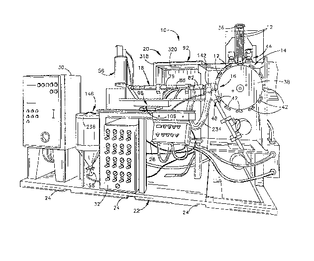
An apparatus 10 (Figs. 1 and 2) for sequentially
applying powder to workpieces 12 includes a conveyor
assembly 14 which sequentially moves the workpieces to a
work station 16. A powder spray gun la is operable to
~pray powder onto each of the workpieces 12 in turn at the
work station 16. A powder supply system 20 supplies powder
to the spray gun 18. The conveyor 14, powder spray gun 18
and powder supply system 20 are disposed on a rigid
platform 22 (Fig. 1) having surfaces 24 which are
engageable to move the apparatus 10 between various
locations.
., .
; The apparatus 10 includes an operator's control panel
28 (Fig. 1) which is positioned at an operator's station.
` A controller 30 includes electrical controls for the
apparatus 10. A second controller 32 includes pneumatic
controls for the apparatus 10. An air dryer (not shown) is
mounted on the platform 22 adjacent to the controllers 30
and 32. The controllers 28, 30 and 32 are disposed on the
platform 22 along with the conveyor 14, powder spray gun 18
and powder supply system 20.
It is contemplated that an apparatus 10 constructed in
accordance with one or more of the features of the present
.. : . .: '
, : ~
'` '
6--
~ 9~2~
invention may be utilized to apply powder to many different
types of workpieces. However, the specific apparatus 10
illustrated in Fig. 1 has been designed for use in
sequentially applying a powder coating to can lids. Thus~
a stack holding ~ssembly 36 is pro~ided to sequentially
supply can lids to the conveyor assembly 14.
.- The conveyor assembly 14 includes a circular turret
38. The turret 38 rotates in a counterclockwise direction,
as viewed in Fig. 1, about a horizontal axis which extends
perpendicular to and is in the same plane as a horizontal
. central axis of the spray gun 18. A plurality of workpiece
holding chuc~s 42 extend radially outwardly from the turret
: 38 to grip the can lids 12. The can lids 12 are held on
the chucks 42 by suction which is applied to a side of the
can lid opposite to a side which is to be coated.
As the turret 38 indexes, or rotates, each can lid 12
is gripped in turn by one of the chucks 42 at a pickup
station 44 (Fig. 1). As the turret continues to index, it
moves each can lid 12 in turn to the wor~ station 16 As
each can lid 12 is indexed to the work station 16, rotation
of the turret 38 is momentarily interrupted
The spray gun 18 is then operated to spray powder onto
the surface of a can lid 12. Although the powder could be
applied to the can lid 12 in any desired pattern, the
powder is applied in an annular band 46 (Fig. 3) to cover
the circular score line 48 on an easy open can lid 12. The
powder is applied to the can lid surface which faces
. ~
2Q~2~
outwardly toward the spray gun 18 (Figs. 1 and 2).
Indexing of the turret is then continued to move the next
succeeding can lid to the work station 16.
The can lids 12 are sprayed at a very high rate.
S Thus, in one specific embodiment of the invention,
approximately three hundred can lids 12 were sprayed during
each minute of operation of the apparatus 10. Therefore,
the spraying of the annular band 46 of powder onto each can
lid 12 must occur during a relatively short period of time.
In one specific embodiment of the invention, indexing of
the turret 38 is stopped to hold a can lid stationary for a
period of approximately one hundred and twenty-five
milliseconds. An annular band 46 (Fig. 3) of powder is
sprayed onto each can lid 12 in turn during operation of
the spray gun 18 for sixty to ninety milliseconds.
Although the nozzle 52 has been specifically designed
to apply an annular band 46 of powder to a can lid 12 at
the work station 16, it is contemplated that the design of
the nozzle 52 could be changed to apply powder in a pattern
having a configuration other than annular and to a product
other than a can lid. Thus, it is contemplated that the
nozzle 52 could be designed to apply powder to the entire
surface of the can lid 12 if desired. It should also be
understood that the specific operating rates for the
apparatus 10 have been set forth herein for purposes of
clarity of description and not to limit the invention to
any specific operating rate.
.. , ~
.
,
-8-
After the annular band 46 of powder has been sprayed
onto the surface of a can lid 12, the can lid is moved to a
discharge station 48 (Fig. 1) where the can lid is released
from a chuck 42. As noted above, the can lid is held on
the chuck 42 by suction which is applied to the can lid.
At the discharge station 48, the application of suction to
the surface o~ tha ca~ lid is interrupted to release the
can lid for downward movement under the influence of
gravity. Although many different types of indexing
machines 38 could be used to convey the can lids 12, one
satisfactory indexing machine is that used for a Model #107
Can End Post Repair Spray Machine, manufactured by H. L.
Fisher Manufacturing Company, Inc. of Des Plaines,
; Illinois, U.S.A.
The powder spray gun 18 has a nozzle 52 (Fig. 2) which
sprays powder on a can lid 12 held by the turret 38 without
engaging the can lid. Since the nozzle 52 does not engage
a can lid 12 at the work station 16, the spray gun 18 can
commence spraying powder onto the can lid as soon as the
can lid has been moved to the work station 16. ~his
enabl~s the can lid 12 to be moved to the work station 16,
- sprayed with powder by the spray sun 18, and moved away
from the work station in a relatively short time.
In addition to the nozzle 52, the spray gun 18 has a
venturi-type powder pump 54 (Fig. 2) which is connected
with a powder feed container 56. Upon actuation of a
solenoid valve 58 to an open condition, air is conducted
'
:''
:
_g _
2Q~ 25
through the venturi-type pump 54 and powder from the
container 56 is entrained in the flow of aix. An amplifier
62 is connected with the pump 54.
Upon operation of a solenoid valve 64, which is
S operated simultaneously with solenoid valve 58, air under
pressure is conducted through a conduit 66 to the amplifier
62. This air is injected into the flow of air and powder
conducted through the amplifier 62 from pump 54 to provide
an additional pumping action. The flow of air with powder
entrained therein moves from the amplifier 62 to a diffuser
70. ~pon actuation of a solenoid valve 72 to an open
condition, air under pressure is conducted through a
conduit 74 to the diffuser 70.
From the diffuser 70, the flow of air with powder
lS entrained therein enters an electrostatic charging unit 76.
The electrostatic charging unit 76 is of the triboelectric
type and includes a plurality of tortuously curved tubes
which extend along the central axis of the powder spray gun
18. As the air and powder passes through these tubes, the
powder frictionally con~acts the walls of the tubes and
picks up an electrostatic charge. The construction of the
pump 54, amplifier 62, diffuser 70 and electrostatic
charging unit 76 is the same as is described in the
aforementioned U.S. Patent No. 4,987,0G1 issued January 22,
1991, which is hereby expressly incorporated herein, in its
entirety, by this reference thereto.
,
.
' ' '
:- .' .
-lo- ~9~72~
A diverter assembly 82 ~Fig. 2) is provided between
the nozzle 52 and electrostatic charging unit 76. The
diverter a~sembly 82 selectively interrupts the flow of
powder to the nozzle 52 to sharply define the trailing end
of the pulse or puff of powder to be applied to a can lid
12. When the diverter assembly 82 is in an active
condition it diverts air or air and powder from a main
passage 84 to conduits 86 and 88. The conduits 86 and 88
conduct the diverted powder to a powder collector container
92 in the powder supply system 20.
Against this background information on the operation
of the system generally, each major component of the system
will now be described in more detail.
Nozzle Positionina SYstem
The nozzle 52 (Fiq. 2) must be accurately positioned
relative to the can lid 12 held on workpiece holding chucXs
42 of turret 18 at work station 16. If the nozzle 52 is
too close to a can lid 12, the can lid may impact against
the nozzle during rotation of the turret 38. If the nozzle
52 is positioned too far away from the can lid 12 at the
work station 16, on the other hand, the annular band 46
(Fig. 3) of powder will not be accurately applied to the
can lid by the nozzle. In one specific embodLment of the
inventionr the nozzle 52 is spaced approximately 1/8 to
3/16 of an inch from the can lid 12 at the work station 16.
Of course, the specific distance between can lid 12 and
nozzle 52 will ~ary depending upon the diameter of the
-: . .
2~972~
turret 38, geometry of nozzle 52, air pressure to the spray
gun pump amplifier 62, and other factors.
In addition to providing for proper placement of the
nozzle 52 the desired distance away from can lid 12 along
the longitudinal central axis of the powder spray gun 18,
it is also necessary to accurately position the nozzle so
that it is concentrically located relative to can lid 12.
For example, if the nozzle 52 is higher than it should be
relative to the work station 16, a band 46 (Fig. 3) of
powder applied to a can lid 12 will be offset upwardly
relative to the center of the can lid. Similarly, if the
nozzle 52 is offset horizontally relative to a can lid 12
at the work station 16, the annular band 46 of powder
applied to the can lid will be offset horizontally relative
to the can lid.
To provide for accurate positioning of the nozzle 52
relative to the can lid 12 at work station 16, therefore, a
three-axis adjustment assembly 96 (Fig. 2) is provided.
Thus, the adjustment assembly 96 is operable to position
the nozzle 52 along X, Y and Z axes, where the X axis is
considered to be the horizontal longitudinal central axis
of the powder spray gun 18. The Y axis is considered to be
a horizontal axis perpendicular to the X axis. The Z axis
is considered to be a vertical axis which is perpendicular
to the X and Y axes.
The adjustment assembly 96 includes a Y axis slide 98
(Fig. 2~. The Y axis slide g8 is movable (into and out of
. ~
; ' '
'
. :
2 0 ~ ~ 7
the page in Fig. 2) along guide tracks 100 and 102 formed
in a base 104. A knob 106 is c~nnected with a lead screw
to effect movement of the Y axis slide 98 along the guide
track~ 100 and 102. An X axis slide 112, Z axis slide 128,
powder spray gun 18, and the powder feed container 56 mo~e
along the Y axis with the Y axis slide 98.
The X axis slide 112 (Fig. 2) is mounted on the Y axis
slide 98. An adjustment screw 114 engages threads in a nut
116 which i8 rigidly connected to X axis slide 112 and is
rotatably journalled in the Y axis slide 98. Upon manual
rotation of a knob 118, the X axis slide 112 is moved (to
the left or right in Fig. 2) relative to Y axis slide 98.
An indicator 122 connected to X axis slide 112 cooperates
with indicia 124 on the Y axis slide 98 to indicate the
15 position of the X axis slide 112 along Y axis slide 98
(i.e., along the X axis).
The Z axis slide 128 is in turn mounted on the X axis
slide 112 and is movable vertically relative to the X axis
slide. A lead screw 130 engages a nut (not shown) which is
rigidly secured to Z axis slide 128 and which is journalled
. for rotation in X axis slide 112. Manual rotation of a
knob 132 rotates the lead screw 130, to move Z axis slide
128 vertically relative to the Y axis slide 98 and X axis
slide 112.
Electrostatic charging unit 76 of spray gun 18 is
.' releasably clamped to Z axis slide 76 and moves with Z axis
slide 76 as does diverter assembly 82 and nozzle 52. Upon
:' .
2 ~
movement of the Z axis slide relative to X axis slide 112,
however, powder feed container 56, pump 54, amplifier 62
and diffuser 70 remain stationary. Flexing movement
between electrostatic charging unit 76 and diffuser 70 as
the Z axis slide 128 is moved is permitted by slip joint 75
which is a short cylindrical tube sealed by O-rings at each
end. of course, powder feed container 56, pump 54,
amplifier 62 and diffuser 70 could be mounted on the Z axis
slide 128 for movement therewith if desired.
An indicator 134 on Z axis slide 128 cooperates with
indicia 136 carried on X axis slide 112 to indicate the
vertical position of the Z axis slide. Although only
indicia 124 and 136 for the X and Z axis slides 112 and 128
has ~een shown in Fig. 2, it should be understood that
similar indicia cooperates with a pointer connected with Y
axis slide 98 to indicate the position of Y axis slide 98
relative to the ba~e 104.
It is contemplated that, from time-to-time, powder
spray gun 18 will be disassembled for cleaning or routine
maintenance. By providing suitable indicia to indicate the
relative positions of the X, Y and Z axis slides, the
powder spray gun can be reassembled and quickly moved back
to the desired position relative to the lid 12 at work
station 16 when the xoutine maintenance has been completed.
Moreover, indicias for the X, Y and Z axis can be used
during test runs to determine the optimal position of
nozzle 52 relative to the workpiece being coated.
,
.'
: - ' ' ' .'' . "
-
: . :
~' : . ' . .:
,
-14- 2~
Powder SUP~1Y Sv8tem
The powder supply system 20 ~Fig. 2) controls the flow
of powder to and from the powder spray gun 18. Powder
supply system 20 supp~ies both virg~n powder and recycled
powdèr to the spray gun 18. Powder supply system 20
receives powder from diverter assembly 82 and an excess
powder collector 142. The excess powdex collector 142,
later described in detail, draws excess powder which does
not adhere to the can lid away from the work station 16 to
the powder collector container 92 of supply system 20.
; Powder supply system 20 is principally comprised of a
. bulk powder container 146 and a powder collector container
; 92, both of which components are described in more detail
later on. Virgin powder is poured into bulk container 146
and is transported from container 146 to the powder
collector container 92 as ~eeded. In powder collector
container ~2, the virgin powder is mixed with the recycled
powder which is returned to the powder collector container
from the diverter assembly 82 and excess powder collector
142. This mixed powder is then transpor~ed from powder
- collector container 92, as needed, to the powder feed
container 56 which is also lat~r clescribed in detail. Feed
container 56 supplies powder to spray gun 18.
Supply system 20 maintains a predetermined minimum
quantity of powder in powder feed container 56 and in the
powder collector container 92. If the quantity of virgin
powder in pulk powder container 146 falls below a minimum
., , ~
-15-
2~72~
predetermined amount of powder, an audible or visual output
signal is provided to the operator of the apparatus 10
indicating that container 146 needs to be manually
refilled.
To enable powder supply system 20 to maintain a
; predetermined minimum quantity of powder in feed container
56, a sensor 150 (Fig. 2), later described, provides an
output signal when less than a predetermined quantity of
powder is in feed container 56. The output si~nal from the
sensor 150 initiates the transport of powder from powder
col~ector container 92 to feed container 56. Likewise, a
sensor 152 senses the quantity of powder in the powder
collector container g2. When sensor 152 senses that the
quantity of powder in the powder collector container 92 is
15 less than à predetermined quantity, an output signal from
:. ~he sensor lS2 initiates the transport of powder from bulk
container 146 to collector container 92. Finally, a sensor
154 is provided to sense when the quantity of powder in the
' .
bulk container 146 is less than a predetermined quantity.
When this occurs, an output signal from the sensor 154
; initiates an audible and/or ~isual alarm to an operator
indicating the need fox manually refilling the container.
Bulk container 146 and the collector container 92 are
vibrated when powder is to be fed from the containers. In
addition, the powder transfer pumps associated with these
containers are vibrated along with the containers 146 and
92. ~ibrating the powder transfer pumps and containers
- ' ' ' ,',' ' ' ' ' ' ,
'
~'
2~9nJ7~5
minimizes any tendency for the powder feed path to clog.
Vibration is a particularly useful method of transport for
the types of powders used in container coating which are
- generally difficult to fluidize. It is also important that
~i 5 the powder be kept dry so that it won't clump together and
. .
this is accomplished by usin~ an air dryer for all
tra~spor~ aix ~sed i~ ~he sys~em.
.~ A vibrator 158 ~Fig. 2), manufactured by ~ibco, Inc.
: of Wyoming, Rhode Island, as Model VS-250, is operable to
vibrate bulk powder container 146 when virgin powder is to
be transported through a conduit 160 to powder collector
container 92. A venturi-type powder feed pump 162, which
; is preferably a pump manufactured by Nordson Corporation of
; Amherst, Ohio, under Part No. 245,477, is connected to bulk
;~ lS container 146 by a relatively rigid conduit 161 to feed
powder to the conduit 160. Pump 162 is vibrated with bulk
, container 146 by the vibrator 158. By vibrating both bulk
container 146 and the pump 162, a flow of powder from bulk
container 146 to pump 162 is promoted. In addition,
vibrating the pump 162 promotes the flow of powder through
the pump 162 to collector 92. Pump 162 and vibrator 158
are operated whenever the sensor 152 indicates that
additional powder is required at the powder collector
container 92. Bulk container 146 is mounted on platform 22
by means of vibration damping pads (not shown) so that the
vibration of container 146 is not transferred to platform
22.
" ~
- - -17-
. A vibrator 166 identical to vibrator 158 is operable
; to vibrate a hopper 168 of powder collector container 92
when powder is to be fed from collector container 92 to
powder feed container 56. In addition to vibrating the
S hopper 168, operation of vibrator 166 vibrates a powder
feed control val~e 172, which is preferably a Series 2600
valve manufactured by ~ed Valve Co., ~nc. of Carnegie,
Pennsylvania, and a feed pump 174, which is identical to
pump 162, during the feeding of powder from collector
10 container 92 to feed container S6 through a conduit 176.
The venturi-type powder feed pump 174 is continuously
; operated by compressed air from controller 32 so that the
; air pressure on the powder in feed container 56 remains
: constant. Powder flow control v~l~e 172 is opened to
lS enable powder to flow from hopper 168 to pump 174 whenever
sensor 150 indicates that additional powder is required at
the powder feed container 56. Li~e bulk container 146,
hopper 168 is mounted on platform 22 by means of vibration
damping pads (not shown) so that the vibration of hopper
20 168 is not transferred to platform 22.
An initial filter 180 (Fig. 2) is provided above the
hopper 168 of collector container 92. Initial filter 180
comprises a pair of hollow cylindrical filter cartridges
which are horizontally mounted side-by-side above hopper
168. Fig. 2 shows a side view of one of the cartridges
180, with the other cartridge being directly behind the one
shown. Each of the filter cartridges 180 is open at one
'
.
.
:. . `
.,
' ' :
,' `
,
' , ' " ~ ~ .. . . ~
-18-
rl 2 ~
- axial end through an opening 310 to a continuously
operating fan assembly 182. Fan assembly 182 continuously
draws air through openings 310 (only one of which is shown
in ~ig. 2) and filters 180 from collector container 92. As
the powder laden air from collector 92 flow~ into the
cartridges 180, the powder collects on the cartridges'
exterior and the cleaned air flows into the cartridges'
`; interior. The fan assembly 182 draws this cleaned air from
the open end of filter cartridges 180, through openings 310
and pressuxes a fan compartment 184 in the powder collector
container 92.
To relieve this pressure, air continuously flows from
the compartment 184 through a final filter 186 to the
atmosphere around the apparatus lO. The final filter 186
removes any powder which may remain in the air after it has
passed through the filters 180. The combination of the
initial and final filters 180 and 186 eliminates the need
to vent air through a stack to the atmosphere outside of a
building containing the apparatus 10. Suitable monitors
may be provided in association with the final filter 186 to
indicate when the final filter should be cleaned. As will
be explained later on in more detail, the powder which is
collected on the exterior of cartridges 180 is periodically
pulsed off to fall into collection hopper 168. This pulse
cleaning mechanism is also described in U.S. Patent No.
4,662,309 which is incorporated herein, in its entirety, by
this reference thereto.
~.,.`
, .
--19--
2~72~
Powder SPraY ~ozzle
The powder spray nozzle 52 (Figs. 3 and 4) is
maintained in a spaced apart relationship with respect to
the can lids 12 as they are sequentially moved to the work
S station 16 (Fig. 2), sprayed with powder at the work
station (Fig. 3), and moved away from the work sta~ion.
Although the can lid 12 and nozzle 52 do not engage each
other at any time during the process, the nozzle is very
close to the can lid when the can lid is at the worX
station 16. Thus, when the can lid 12 is at the work
~tation 16, front surface 192 of can lid 12 is spaced
approximately 1/8 to 3/16 of an inch from the nozzle 52.
The nozzle 52 sprays powder onto the surface 192 (Fig.
3) of the can lid 12. The powder is deposited on the can
lid in an annular band 46. Although the annular band 46 of
powder could be disposed at many places on the can lid 12,
the powder is shown in Fig. 3 as being deposited over a
circular score line 196. After the can lid 12 has been
moved away from the work station, the powder is heated and
forms a protective coating over the score line 196.
Nozæle 52 includes a generally conical powder flow
channel 200 through which air with powder entrained therein
flows toward the can lid 12. Powder flow channel 200 is
formed between an inner deflector cone 202 and an outer
25 deflector cone 204. Inner deflector cone 202 engages the
center of a str~am 206 of air and powder as the stream
enters n~zzle 52.
'.
'
' ' ` ` : .'. .
-
,
-20-
2~7~5
When stream 206 (Fig. 3) of air and powder enters
nozzle 52, stream 206 has a solid circular cross sectional
" configuration. Inner deflect~r cone 202 opens stream 206
as the air and powder flows around a conical outer side
æurface 208 of inner cone 202. As the stream 206 flows
around cone 202, the cross sectional configuration of the
stream becomes annular. As cone 202 flares radially
outwardly and stream 206 moves toward can lid 12, cone 202
opens up the central portion of the stream to increase the
inside diameter of the annular cross section of stream 206.
The outer deflector cone 204 cooperates with the inner
- cone 202 to limit the extent to which the inner cone 202
expands the annular cross sectional configuration of stream
206 of air and powder radially outwardly. ~hus, a conical
inner side surface 210 on outer cone 204 is evenly spaced
from outer side surface 208 of inner cone 202. In one
specific embodiment of the invention, outer surface 208 of
cone 202 and inner surface 210 of cone 204 are spaced apart
by a radial distance of approximately 0.1875 inches. The
annular band 46 of powder deposited on the can lid 12 has
approximately the same radial extent. Of course, the
spacing between the surfaces of the inner and outer
deflector cones 202 and 204 and the radial extent of the
band 46 of powder may be different than the foregoing
2~ specific dimension if desired.
In one specific embodiment of the noæzle 52, inner
deflector cone 202 had a maximum outside diameter, at the
':
., . -:
: ,
.
-21-
2~72~
axially outer or rightward (as viewed in Fig . 3 3 end of the
cone 202, of approximately 2.5 inches. This resulted in
the annular band 46 of powder deposited on can lid 12
having an inside diameter of approximately 2.5 inches. Of
5 course, the annular band 46 of powder could have a
different diameter if desired.
A body section 214 of the powder spray gun 18 is
telescopically inserted into the axially inner or left (as
viewed in Fig. 4) end of outer deflector cone 204 of the
nozzle 52. The nozzle 52 is in this way supported by the
outer end portion of the body section 214.
In the illustrated embodiment of the invention, the
inner and outer deflector cones 202 and 204 of the nozzle
52 are shaped to cause the powder to be deposited on the
can lid 12 in an annular band 46 (Fig. 3). It is
contemplated that the inner and outer deflector cones 202
and 204 of the nazzle 52 could have a different
configuration so that the powder is deposited on the
surface 192 of can lid 12 in a different pattern. By
properly shaping the flow path 200 along which the powder
flows through the nozzle 52, almost any desired pattern of
powder deposition can be obtained on the major side surface
192 of the can lid 12. Moreover, if desired, the entire
surface 192 of the can lid 12, or the entire interior of a
container, could be coated with powder from an
appropriately designed spray nozzle.
--22--2 ~ 9 ~ rl 2 S
Bxcess Powder Collector
The excess powder collector 142 partially encloses and
is supported by nozzle 52. Excess powder collector 142
draws a flow of excess powder which does not adhere to can
lid 12 away from the can lid (Fig. 3) and bacX toward the
outer periphery of nozzle 52. ~he reverse or backf low of
oversprayed powder is drawn into a generally conical cavity
218 which is disposed inside a collector housing 220 and
extends around the nozzle 52. The flow of excess powder
away from can lid 12 into cavity 218 prevents powder from
entering the atmosphere around the work station 16.
The collector housing 220 is maintained in a spaced
apart relationship with respect to can lid 12 during
movement of the can lid 12 to and from work station 16 and
during spraying of can lid 12. The space between the
collector housing 220 and the surface 192 of the can lid 12
at the work station 16 is approximately the same as the
spacing between the nozzle 52 and the surface 192 of the
can lid 12, that is, approximately 1/8 to ~/16 of an inch.
Since the excess powder collector housing 220 is mounted on
the nozzle ~2, operation of the adjustment assembly 96
positions the excess powder collector 142 relative to can
lid 12 at the same time as the nozzle 52 is positioned
relative to can lid 12. By having both the collector
housing 220 and the nozzle 52 spaced from the can lid 12 at
all times, the conveyor 14 (Figs. 1 and 2) can quickly move
: the can lid 12 to and from the work station 16.
-23-
2 ~ 2 ~
Collector housing 220 is supported on outer deflector
cone 204 of nozæle 52. A conical outer side surface 224 on
deflector cone 204 cooperates with a conical inner side
surface 226 on collector housing 142 to form the generally
conical chamber 218 in which excess powder is collected.
The chamber 218 has a generally annular cross sectional
configuration in a plane which extends perpendicular to the
longitudinal central axis of spray gun 18.
A continuously operated venturi-type fluid amplifier
10230 (Fig. 2) is mounted on the collector container 92 and
i~ connected in fluid communication with excess powder
chamber 218 by a conduit 234. Amplifier 230, later
described, provides a pumping action which continuously
reduces the fluid pressure in the conduit 234 and draws
oversprayed powder away from the surface 192 (Fig. 3) of
the can lid 12 into the chamber 218. This flow of powder
i6 conducted through an outlet 232 from chamber 218 to
conduit 234 (Fig. 2) leading away from excess powder
collector 142 and into powder collector container 92.
Since amplifier 230 is continuously operating, it produces
'Aa continuous flow of air away from the work station 16.
Therefore, any oversprayed powder produced at work station
16 at any time is drawn into chamber 218 and transported to
collector 92.
.~'
Di~erter A~emblY
The di~erter assembly 82 (Figs. 2 and 4) periodically
diverts powder flowing through spray gun 18 away from the
, .
,,
- -24-
2 Q 9 ~
nozzle 52. The diverter assembly 82 is normally in an
active condition directing air or powder flow in gun 18
away from the nozzle 82 through passages 238 and 240 (Fig.
- 4) leading to the conduits 86 and 88 (Fig. 2). When powder
is to be sprayed from the nozzle 52 onto a lid 12, the
diverter assembly 82 is changed to an inactive condition in
which it does not divert powder flowing through the ~un
away from nozzle 52 but instead allows it to pass into and
. through nozzle 52. Then when the flow of powder from the
nozzle 52 is to be interrupted again, diverter assembly 82
is changed back to the active condition in which powder
flow from the main passage 84 of gun 18 is diverted into
passages 238 and 240 (Fig. 4).
The diverter assembly 82 includes a pair of air
: 15 amplifiers 244 and 246 which induce a flow of air and
powder from the main passage 84 to the divexter conduits 86
and 88 when the diverter assembly is in its normal active
condition. The flow of air and powder from the main
l passage &4 through the amplifiers 244 and 246 is conducted
;~ 20 by the conduits 86 and 88 to the hopper 168 of the powder
collector 92. When the diverter assembly 82 is in an
inactive condition, the amplifiers 244 and 246 are turned
off and are therefore ineffective to induce a flow of air
; and powder from the main pas~age 84.
Air amplifier 244 is illustrated in Fig. 5. Amplifier
244 includes a venturi-type nozzle 250 having an inlet 252
which is connected in fluid communication with main passage
-25-
2~n9~3~,~
84 through diverter passage 238. The venturi-type nozzle
250 has an outlet 254 which is connected in fluid
communica~io~ with the conduit 86.
To induce a flow of air with powder entrained therein
S from the main passage 84 through the amplifier 244 to the
conduit 86, a solenoid valve 258 (Fig. 2) is actuated to an
open condition to direct a flow of air under pressure to an
inlet 260 (Fig. 5) to the amplifier. The air flows from
the inlet 260 through passages 262 at the throat of the
nozzle 250. The flow of air into nozzle 250 through the
passages 262 draws air with powder entrained thereinr from
- the main passage 84 through diverter passage 238 to the
conduit 86. The rate of flow of air with powder entrained
therein, from the outlet 254 of the nozzle 250, is a
substantial amplification of the rate of flow of air
through the inlet 260 of the amplifier 244. This results
in a pu~ping action which draws the flow of air with powder
entrained therein from the main passage 84 through the
amplifier 244.
The diverter assembly 82 includes a second amplifier
246 (Fig. 2) having the same construction as the amplifier
244. The amplifier 24b is effective to induce a flow of
air with powder entrained therein through diverter passage
240 from a side of the main passage 84 opposite to the
2S amplifier 244. The combined effect of the two amplifiers
244 and 246 is to induce the entire flow of air with powder
entrained therein to leave the main passage 84 and flow
-26-
through the diverter assembly 82 to the conduits 86 and 88,
so that flow towards spray nozzle 52 is cut off. A second
; solenoid 264 is provided to control the flow of air to the
amplifier 246.
Although the amplifier 244 has been described in
connection with the diverter assembly 82, it should be
understood that the amplifier 230 which induces a flow of
air and powder from the excess powder collector 142 has the
same general construction and mode of operation as the
amplifiers 244 and 246. However, the amplifier 230 which
draws the excess powder from the chamber 218 (Fig. 4), is
somewhat larger than the amplifiers 244 and 246 and has a
greater flow capacity. Likewise, the other amplifiers
which form a part of this powder coating system, such as
amplifier 62, are also of the same general configuration as
i8 ~hown in Fig. 5.
Bulk Powder Container
As mentioned above, collector 92 (Fig. 2) i5 supplied
with virgin powder from bulk powder container 146 as
needed. When the bulk powder container 146 is to be filled
with virgin powder, a cover 266 (Fig. 1) is removed from
bulk container 146. This opens a circular upper end
portion 268 (Fig. 6) of bulk container 146.
A horizontal annular side wall 270 extends inwardly
from a rim 272 (Fig. 6) of the opening 268. Annular side
plate is connected to a vertically dow~wardly extending
cylindrical wall 274. A sieve or screen assembly 276 is
-27-
2~7~,5
disposed in axial alignment with the downwardly extending
wall 274. The sieve or screen assembly 276 includes an
upwardly extending cylindrical wall 278 which
telescopically overlaps the downwardly extending wall 274.
: 5 A screen 280 extends across the inner wall 278.
To fill bulk powder container 146 with virgin powder,
the pswder is poured from a ~ag or box into the open upper
e~d of the cylin~rical wall 274. ~he powder flows
downwardly onto the screen 280. Some powder flows through
screen 280 and some rests on screen 280 until the vibrator
: 158 is operated to vibrate the bulk powder container 146.
Upon operation of the vi~rator 158, the virgin powder is
. vibrated through the screen 280 and falls downwardly
through a circular open lower end porti~n 282 of screen
a6sembly 276 into bulk powder container 146. As the powder
falls through the screen 280, it is aerated and otherwise
conditioned for use by the powder spray gun 18.
Screen assembly 276 (Fig. 6) is mounted on a
canti~evered arm 286. Arm 286 extends inwardly from a
.; Z0 cylindrical side wall 288 of bulk container 146. As
previously described, vibrator 158 vibrates container 146.
The cantilevered mounting arrangement for screen assembly
276 allows the screen 280 to vibrate with container 146
: during operation of the vibrator 158. In fact, the
cantilever support design amplifies the vibration of screen
280 relative to the container 146 as the container vibrates
which enhances breaking up of the powder so that it can
;
- ~ ~
'
-28-
~ 7
fall through the screen into the conical bottom portion of
container 146. If desired, a switch could be provided at
the bulk powder container 146 to enable an operator to
initiate operation of the ~ibrator 158 as the container is
filled.
As the powder falls downwardly through the cylindrical
wall 274 (Fig. 6) toward screen assembly 276, it is
contemplated that dust will be generated. This dust, or
powder drifting in the air, is drawn radially outwardly
10 through circular openings 292 formed in the side wall 274.
The flow of air and dust through the openings 292 is
conducted to an outlet 294 by an air amplifier 296 which is
provided to induce a flow of air and powder through the
opening 294 to a conduit 298 ~Fig. 2). Conduit 298 is in
:; 15 turn connected to an inlet 3~0 to hopper 16~ in the powder
:,
collector 92. Amplifier 296 is of the same design as is
. shown in Fig, 5.
:~ During operation of the apparatus 10, virgin powder
will be supplied from the bulk powder container 146 to the
20 powder collector container 92 through the pump 162 and
conduit 160. When the quantity of powder in the bulk
powder container 146 has been decreased to less than a
predetermined amount, the sensor 154 will provide an
appropriate output signal~ The output signal from the
2S sensor 154 triggers a visual and/or audible alarm to an
operator indicating that the bulk powder container 146
should be refilled. The sensor 154 is positioned opposite
--2g--
2 ~ 2 ~
~ a transparent plastic window (not shown) provided in the
: side wall of hopper 146 to read the level of powder in
hopper 146. Sensor 154, in the presently preferred
embodiment, is a capacitive proximity switch which is
; S commercially available under the designation KGE-2008-FBOA
from Efector, Inc., A subsidiary of IFM Electronic and
ha~ing a place o ~usiness in Exton, Pennsylvania. Of
cour~e, other ~ypes o particulate matter level sensors
could be used if desired.
Powder Collector Container
The powder collector container 92 t~ig. 2) f~nctions
as a central receiving location from which powder is
transported to the powder spray gun 18 and to which powder
is diverted from the powder spray gun and from excess
15 powder collector 142. Powder collector container 92
include6 a relatively large housing 302 which encloses the
hopper 168 and fan assembly 182. Housing 302 has an inlet
` 3~4 which is connected to conduit 160 from bulk container
146. Whenever sensor 152 detects that the quantity of
powder in ~he hopper 168 is less than a predetermined
quantity, sensor 152 produces an appropriate output signal
to controller 30 and pump 162 is turned on to transport air
~ with virgin powder entrained therein through the conduit
160 to the inlet 304. Sensor 152 is identical to sensor
25 154, and liXe sensor 154, senses the level of powder in
hopper 168 through a transparent window (not shown) which
is provided in the side wall of hopper 68.
. ' ~ .
-30-
During spraying of workp~ c~ at the wor~ station
- 16, excess powder is conducted from the excess powder
collector 142 through the conduit 234 and amplifier 230 to
a second inlet 306 to powder collector 92. Powder is also
diverted into collection hopper 168 through inlet 300 from
screen assémbly 276, and through the inlets for diverter
conduits 86 and 88 as previously described, and also
through an inlet for conduit 337 from feed hopper 56 which
will be descxibed later on. Ha~ing deli~ered the powder
into hopper 168 from these various sources, it is necessary
to separate the powder from the transport air. Cartridge
filters 180 in collector 92 serve to fulfill this function.
The interiors of filter cartridges 180 are connected
in fluid communication with the fan assembly 182 through
15 openings 310 formed in the wall of the hopper 168 and a
wall of the housing 302 separating the hopper 168 from the
fan chamber 184 as previously mentioned. The fan assembly
182 continuously induces a flow of air through filter
cartridges 180. This flow of air results in the powder
being deposited on the outside of the filter cartridges 180
as the cleaned air flows into the interior of the
cartridges. This cleaned air is then drawn from the
interior of cartridges 180 through openings 310 and into
fan chamber 184 by fan 182 and is then exhausted through
25 final filter 186 to the atmosphere around the apparatus 10.
To prevent cartridge filters 180 from cloggingr high
pressure pulses of air are intermittently directed into the
`:
-31-
2 ~ 2 5
filters to highly pressurize the inside of filter 180 and
thereby blow the powder off of the outside of the filters.
To accomplish this, a solenoid valve 312 (Fig. 2~ is
periodically actuated to direct a flow of air through a
conduit 314. The conduit 314 is axially aligned with the
opening 310 and the longitudinal axis of one of the filter
cartridges 1~0. A second conduit and solenoid valve (not
shown)~ c~r~espondi~ ~o the con~uit 314 an~ solenoid valve
312, are provided to permit pulse cleaning of the second
filter cartridge. The axial flow of air into the filter
cartridges lB0 blows the powder off of the outside of the
cartridges 180 so that the powder can fall downwardly into
the hopper 168 for transport through pump 174 to feed
, hopper 56.
lS Powder is conducted from the hopper 168 (Fig. 2) to
the feed powder container 56 through the conduit 176. To
establish a flow of powder through the conduit 176,
pneumatically actuated pinch valve 172 is opened. With
valve 172 open, powder pump 174 pumps a flow of air with
powder entrained therein through the conduit 176 to the
; powder feed container 56. The venturi-type powder pump 174
is always operating as mentioned above. Therefore, when
the pinch valve 172 is closed, the pump 174 is effective to
maintain a constant fluid pressure on the powder in the
powder feed container 56. Pinch valve 172 and pump 174 are
; connected to the hopper 168 and are vibrated with the
,'. .
-32-
2~72~
hopper ~y the vibrator 166. Vibrator 166 is operated
whenever pinch valve 172 is open.
The housing 3~2 of the powder collector container 92
has an open upwardly extending hood 318 (Fig. 1). A
rectangular opening 320 is formed in the side of the hood
318 which faces toward the powder spray gun 18. The fan
assembly 182 is effective to induce a continuous flow of
air through the opening 320 into the powder collector
container 92.
In the unliXe~y event ~f a fire in collector 92,
pressure can escape from the powder collector container 92
through the opening 320 in the hood 318. This prevents a
potentially explosive build up of pressure within the
powder collector container 92.
Powder Feed Container
A generally cylindrical powder feed container 56 (Fig.
2) is mounted above the powder pump 54 of the spray gun 18.
During operation of the spray gun 18, powder is drawn from
the powder feed container 56 by the powder feed pump 54.
Powder feed container 56 is supplied with powder from
powder collector 92.
The powder feed container 56 includes a cylindrical
housing 324. A stirrer 326 (Fig. 7) is disposed along the
vertical central axis of the housing 324 and includes four
radially disposed arms 340. The stirrer 326 is slowly
rotated, at approximately one revolution per min~te, by a
motor 327. The stirrer 326 gently disturbs or agitates the
:
-33-
20~72~
powder tD pr~mote fluidization and flow of the powder from
the container 324 into the powder pump 54.
Fluidization of the powder in the container 324 is
also promoted by a flow of air through a fitting 328 (Fig.
7) into an annu7ar ch~mber 330 dispose~ beneath a porsus
plate 332. The air flows upwardly from the chamber 330
through the plate 332 and the powder in the housing 324.
~; The aix, with some powder entrained therein, is exhausted
irom the h~using through a gra~ity type chec~ valve 336
whenever the pressure in container 324 is enouqh to unseat
check valve 336. This air and powder i6 conducted from
container 336 to the hopper 168 in the powder collector
container 92 through a conduit 337.
The upward flow of fluidizing air through the powder
15 in the housing 324 and the stirrer 326 maintain the powder
. in a loose and fluidized condition. This facilitates
:: uniform flow o powder into the powder pump 54.
The sensor 150 (Fig. 2), which is identical to sensors
1~2 and 154, senses the ~uantity of powder in the container
20 324 through a transparent window 32~ provided in the side
wall of container 324 and, when less than a predetermined
level of powder is present, provides an appropriate output
signal to controller 30. The output signal from the sensor
150 initiates the opening of pinch valve 172 and activation
of vibrator 166 to transport powder from the powder
collector container 92 through the conduit 176 to the
powder feed container 56. The flow of powder from the
-34-
2 ~ 2 ~
conduit 176 enters the housing 324 (Fig. 7) tangentially
through an opening 342. By having a tangential flow of
powder into the housing 324 through the opening 342, a
swirling effect is obtained which promotes fluidization of
the powder. This swirling effect is also produced when no
powder is enterinq housing 324 since even when pinch valve
172 is closed compressed air is ~eing transported ~hrough
open-~g 342 ~y pump ~74 whic~ is co~tLnu~sly operating to
maintain relatively constant pressure conditions inside
hopper 56 whether or not powder is then being transported
into the hopper. By maintaining a constant pressure
condition and a controlled powder level in hopper 56,
powder flow through pump 54 is made uniform from pulse to
pulse. The pressure conditions in hopper 56 also determine
how much powder is entrained in each pulse of powder
discharged from pump 54, with higher pressure conditions
resulting in more powder being entrained in each pulse.
` Fire Protection
It is contemplated that, due to the fact that the
powder is electrostatically charged, a fire could occur
between the nozzle 52 and can lid 12. A fire detection
apparatus 350 (Fig. 4) is provided to detect the occurrence
of such a fire. Upon the occurrence of a fire between the
nozzle 52 and a can lid 12, ~he fire will be drawn into the
excess powder collector cavity 218 due to the negative
pressure condition therein. From there, the fire will be
. drawn into conduit 234 leading to ~he collector container
;:
-35-
2Q~72~
92. A filament or line 354 extends across conduit 234 from
an arm 356 of a switch assembly 352 to a fixed connection
360 on a side of the conduit 234 opposite from switch
assembly 352. The filament or line 354 is formed of
material which fuses or burns upon even a relatively brief
exposure to flame or heat. Although the filament 354 could
have many different constructions, it is presently
preferred to fonm the filament with a relatively rigid
p~lyester core surrounded by a iac~et of nylon. The manner
in which the filament 354 is constructed and cooperates
with the switch 352 is the same as is disclosed in U.S.
Patent No. 4,675,203 which is hereby incorporated herein,
in its entirety, by this reference thereto.
Upon the occurrence of a fire between the nozzle 52
and can lid 12, the fire will be drawn through excess
powder collector 142 to conduit 234. Upon entering conduit
234, the fire will burn through filament 354 releasing the
spring biased arm 356 of the switch assembly 352. ~hen the
arm 356 is released, contacts in the switch assembly 352
provide an output signal to the controller 30. Upon
receiving a signal from the switch assembly 352, the
controller 30 completely shuts down the apparatus lO which
cuts off further powder flow through the gun and prevents
the fire from being drawn into collector 92 so that the
fire extinguishes itself for lack of additional fuel.
Although one spcciflc fire detection apparatus 350 has oeen
.
'' .. ' '
:
2 ~ 9 ~
illustrated, it should be understood that other known fire
detection apparatus could be utilized if desired.
Operation
When operation of the apparatus 10 is to be ~nitiated,
the spray gun 18 and excess powder collector 142 are
accurately positioned relative to the can lid 12 at work
station 16 and turret 38. This is accomplished by
operating the three-axis adjustment assembly 96 (Fi~. 2) to
first move the X axis slide 112, spray gun nozzle 52 and
excess powder collector 142 along an axis which is
coincident with the longitudinal central axis of the spray
gun (X axis). The nozzle 52 and excess powder collector
142 are then positioned sidewardly relative to a can lid 12
at work station 16 by moving the Y axis slide 98 relative
to the base 104. The nozzle 52 and excess powder collector
142 are then positione~ vertically relative to the work
station 16 by moving the Z axis slide 128. Several can
lids, or other workpieces, can be positioned in this way
and then coated to find the optimal position of spray gun
18 relative to can lid 12. The X, Y and Z indicias can
then be recorded to ensure that this position is
maintained.
The powder supply system is then checked ~o be certain
that powder supply containers 56, 92 and 146 contain the
; 25 proper amount of powder. If they do not, they are filled
to the desired levels. The supply of can lids in the
holder 36 is then checked to ensure that it is adequate.
.
-
-37-
2 ~ 2 ~
Operation of the conveyor assembly can now be initiated so
that turret 38 rotates to index a first can lid 12 to the
work station 16.
As the first can lid 12 moves to the work station 16,
the solenoid valves 58 and 64 (Fig. 2) are opened to
provide a flow of compressed air through the powder pump 54
and amplifier 64, respectively. This pumps powder from
feed hopper 56 through pump 54 and amplifier 64 into
diffuser 70, and through diffuser 70 to the electrostatic
char~ing unit 76. Solenoid 72 of diffuser 70 is always
open during operation of the system to provide continuous
air flow through diffuser 70 to purge the gun hetween
pulses as is explained in U.S. Patent No. 4,987,001 which
has been incorporated by reference. By purging the gun
between pulses, the air from diffuser 70 flows up into feed
container 56 to keep powder from container 56 from falling
into pump 54 when pump 54 is not being operated.
At this time, the diverter assembly 82 is in the
active condition. That is, solenoid valves 258 and 264 are
open 80 that compressed air is passing through amplifiers
244 and 246. Shortly after solenoids 58 and 64 are
energized, however, perhaps 10 milliseconds which is
estimated to be the amount of time it takes for the front
of the powder pulse to travel down spray gun 18 from pump
S4 to diverter assembly 82, solenoids 258 and 264 are de-
energized to allow the powder pulse to pass through the
passage 84 of spray gun 12 to the nozzle 52.
,
' . .
:
. . ~
.
~-; -
~ 2 ~ 9 9 ~ 2 ~
-s As the stream 206 of air with powder entrained therein
enters the nozzle 52, the stream has a solid circular cross
sectional configuration. The inner deflector cone 202
(Fig. 3) opens the central portion of the stream 206. This
results in the stream 206 having an annular cross sectional
area as viewed in a plane extending perpendicular to the
longitudinal central axis of the spray gun 18.
~ s ~he fl~w of p~wder c~ntinues through the annular
powder flow channel 200 in the nozzle 52, the stream 206 of
powder is expanded radially outwardly. Radial expansion of
the stream 206 continues until the cross sectional size and
configuration of the stream corresponds to the desired
configuration of the annular band 46 (Fig. 3) of powder to
be deposited on the surface 192 of can lid 12. Due to the
lS electrostatic charge which has been applied to the powder,
a layer of the powder adheres to the can lid 12 to form an
annular band 46 of powder. Thi~ adhering of the powder
occurs e~en when the lid 12 is electrically insulated, such
as by mounting it on a plastic vacuum chuck 42, in that the
lid will still have a different electrical potential than
the charged powder.
As a coating of powder is being applied in an annular
band to the can lid 12, excess powder which does not adhere
to the can lid, is drawn into the chamber 218 in the excess
~- 25 powder collector 142. The excess powder is drawn from the
chamber 218 and through the conduit 234 by the continuously
- operated amplifier 230.
:
.;, ., . : ~ : -
. . , ~ ,
~ - -39-
2 ~ 9 ~ r~
After the solenoid ~ralves 5g and 64 (Fig. 2~ have been
on for approximately 80 milliseconds, for this application,
they are turned off to interrupt the pumping of powder from
feed hopper 56. Approximately 20 milliseconds thereafter,
solenoids 2S8, 264 for amplifiers 244, 246 in the diverter
assembly are activated to divert the flow of powder away
from the nozzle 52 ~y drawi~g air with powder entrained
therein from the main passage 84 through the conduits ~6
and 88 to collector 92. This diverted powder comprises the
"tail~ of the powder pulse, and by cutting the tail of the
pulse off, the pulse of powder coating material sprayed
toward lid 12 is cleanly cut off. The turret 38 i5 then
- rotated to move the just coated can lid 12 from the work
station 16 and to move the next succeeding can lid 12 to
work station 16.
In the illustrated embodiment of the invention, it is
preferred to establish an intermit~ent flow of air and
powder from the powder spray gun 1~ by interrupting the
10w of air and powder through the pump 54 tFig. 2)
: 20 connected to the powder feed container 56. However, if
desired, the pump 54 could be continuously operated. If
this was done, there would be a continuous flow of air
through the solenoid control valve 58 and a continuous flow
; of air and powder through the pump 54. The diverter
assembly 82 would be operated to interrupt the flow of air
and powder to the nozzle 52 during movement of a can lid 12
to and from the work station 16. The diverter assembly 82
. .
-
' ~ ~
-40-
2 ~ 2 5
wo771d be rendered inactive only when a can lid at the work
station 16 is to be sprayed with powder.
Can lids are processed at a rate of approxLmately
three hundred per minute. This high speed operation is
obtainable because powder spray gun 18 does not interact
with (i.e., contact) the can lid other than to direct a
flow of powder onto the can lid. Thus, the nozzle 52 and
excess powder collector 142 remain spaced apart from the
can lids 12 during movement o the can lids to and from the
wor~ station 16 and during spraying of powder onto the can
lids at the work station. If it is necessary to
disassemble the powder spray gun 18 for cleaning or routine
maintenance, the indicia associated with the slides 98, 112
and 128 upon which the spray gun is mounted enables the
spray gun to be quickly and easily returned to its original
position relative to the work station 16.
During operation of the powder spray gun 18, the
quantity of powder in the powder feed container 56 is
decreased. When the quantity of powder in the powder feed
container 56 falls below a predetermined level, the sensor
150 provides an appropriate output signal to controller 30
which initiates operation Qf the pinch valve 172 (Fig. 2)
from a closed condition to an open condition. Opening of
the pinch valve 172 enables powder to flow from the hopper
25 168 in collector 92 through the continuously operating pump
174 to the powder feed container 56. Simultaneously with
opening of the pinch valve 172, the vibrator 166 is
'. . ~ ' :
, .; ~ :
,, :
:
. .
- -41-
2a9972~
operated to vibrate the hopper 168, pinch valve 172 and
pump 174 to promote the even flow of powder to khe feed
- container 56.
If the level of powder in the hopper 168 of the powder
collector container 92 falls below a predetermined level,
the sensor 152 provides an appropriate output signal to
; controller 30 which initiates operation of the powder feed
pump 162 to feed powder from the bulk powder container 146
to collector 92. Simultaneously with initiation of
10 operation of the powder feed pump 162, the ~ibrator 158 is
activated. Operation of the vibrator 158 vibrates the bulk
`; powder container 146 and the powder feed pump 162 to
promote the even flow of virgin powder from bul~ container
146 to collector hopper 168.
The cartridge filters 180 disposed in the hopper 168
of the powder collector container 192 remove the powder
from the air. Blaats of compressed air are periodically
directed into the cartridges 180 to dislodge any powder
which accumulates on the exterior thereof. A fan assembly
; 20 182 promotes a continuous flow of cleaned air through the
filters 180 and through the final filter 186 into the
atmosphere around the apparatus 10.
During continued operation of the powder spray gun 18,
the level of powder in the bulk powder container 146 may
fall below a predetermined level. When this occurs, the
sensor 154 provides an appropriate output signal to
controller 30 which in turn initiates operation of an alarm
~' , .
,:
., -. -
: .
,
:
-42-
2Q9972~
to notify the operator of the powder spray gun 18 that
additional powder is required in the bulk powder container
146.
Spraying Can Bodies
The foregoing description of the method of operation
of the apparatus 10 has ~een in conjunction with the
spraying of a~nular bands 46 ~f powde~ o~to can 7ids 72.
However, it is contemplated that the apparatus 10 could be
utilized to spray powder on many different articles,
including can bodies. Use of the apparatus 10 to spray the
interior of can bodies 366 is illustrated schematically in
Fig. 8. One end of a cylindrical can body 366 is closed by
an end wall and is engaged by one of the chuc~s 42a. The
opposite end of the can body 366 is open and faces toward
the spray gun 18.
As the turret 38 indexes, each can body 366 is moved
in turn from a pickup station (not shown) to the work
station 16. As each can body 366 is moved to the work
station 16, rotation of the turret 38 is momentarily
interrupted. A central axis of the cylindrical can bod~
366 i8 coincident with a central axis of the spray gun 18
and nozzle 52 when the can body is at the work station 16.
The spray gun 18 is then operated to spray powder into
the open, outwardly facing end of the can body 366. Powder
is applied into the can body through a nozzle 400 having a
single central opening. The pulse of powder sprayed
through nozzle 400 first impacts the bottom of the can and
. - .
; -' ' : ' ' ' ' ' ' ' , :
,
- . . .
.
., ~
.
2 ~ 7 2 ~
is then drawn by excess powder collector 192 back along the
walls of the can so that both the bottom and side walls of
the can are coated. Any excess powder which does not
adhere to the can is drawn into excess powder collector 192
and xeturned to collector 92. The system operates in the
identical manner to that described above for the coating of
can lids.
Having described the structure and operation of
apparatus for ~oth can li~ coati~g and can interior
coating, it ~hould ~ow also be appreciated tha~ the
invention also encompasses various ~ovel methods,
One such method involves the use of an X-Y-Z
positioning apparatus to accurately position the spray gun
relative to the container or closure being coated.
Another involves the application of an annular spray
pattern to can ends to coat a score line thereon.
Still another involves the ~praying of powder down
into the middle of a can to impact the bottom and then
causing it to return along the sides of the can for
complete coverage of the can.
Yet another involves the use of a diverter within the
gun to divert the tail of the pulse of powder sprayed
through the gun so that a sharply defined pulse of powder
is applied to the workpiece.
2S While preferred embodiments of the invention have been
described, it is evident that many other alternatives,
modification6 and variation~ will be apparent to those
, ' . :
.. .
.
2 ~
skilled in the art in light of the foregoing description.
Accordingly, the invention is intended to embrace all such
alternatives, modifications and variations as fall within
the spirit and scope of the appended claLms.
. . . ~
:
." '. .