Note : Les descriptions sont présentées dans la langue officielle dans laquelle elles ont été soumises.
2100016
ELE TRICAL HEATER
C
BACKGROUND OF THE INVENTION
This invention relates generally to electrical resistance
heaters and, more particularly, to electrical sheath heaters.
Sheath heaters, such as cartridge heaters, conventionally
comprise a resistance element, typically coiled on an insulating
core, and a metal sheath that is coaxial with the coil and core and
radially spaced from the coil. A mineral insulating material
having an optimum combination of relatively high thermal
10 conductivity and relatively low electrical conductivity fills the
space between the sheath and the coil. Power is delivered to the
heater through internal lead pins contained within longitudinal
holes in the core where they are held in electrical contact with
the resistance element. External leads, having insulating sleeves,
15 are connected to the lead pins and extend through an open end of
the heater.
When power leads are in high temperature environments (e.g.,
in excess of 1000F), insulating sleeves often become baked out and
brittle. When this happens, any amount of flexing of the external
20 leads causes the sleeves to fray and thereby expose the conductors,
with the likely result being electrical shorting between the
conductors or a grounded surface.
Another problem frequently encountered by sheath heaters is
contamination of the internal components. Contamination occurs
25 when foreign materials enter the heater and cause a breakdown of
the coil or surrounding insulation. The contaminants may cause a
gross electrical shorting or an accelerated deterioration of the
internal elements of the heater. Heaters that are subject to large
temperature swings or frequent cycling are most susceptible to
30 ingesting harmful contaminants. When a heater heats up and cools
2100016
down causing thermal expansion and contraction of the air inside
it, it "breathes" surrounding gasses or liquids -- as well as any
contaminants within the gasses or liquids.
Another problem encountered by sheath heaters is contamination
5 by the heaters of the environments they are used in. Contamination
(i.e., outgassing) occurs when moisture and/or gasses escape from
the heater. In some applications -- such as when the heater is
being used in a vacuum environment -- outgassing may be undesirable
or unacceptable.
10 SUMMARY OF THE INVENTION
Among the objects of the present invention may be noted the
provision of an improved sheath heater which overcomes the
disadvantages and de~iciencies associated with the prior art
devices; the provision of such a sheath heater having power leads
15 capable of withstanding high temperatures; the provision of such a
sheath heater which prevents contaminants from entering the heater;
and the provision of such a sheath heater which prevents
contaminants escaping from the heater.
Generally, an electrical heater of the present invention
20 comprises a heating element, a tubular metal sheath surrounding the
heating element and spaced therefrom, insulation inside the sheath
for electrically insulating the heating element from the sheath,
and a closure closing one end of the sheath. Power lead means
adapted for connection to a source of electrical energy extend
25 through passaging through the closure, the passaging extending in
a direction generally lengthwise of the sheath. The power lead
means comprises electrical conductor means, metallic sleeve means
surrounding the conductor means, and insulation means electrically
insulating the conductor means from the sleeve means. The
30 conductor means has terminal portions electrically connected to the
heating element. A seal between the closure and the sheath around
the one end of the sheath seals against the passage of contaminants
2100016
between the closure and the sheath. A seal between the power lead
means and the closure seals against the passage of contamlnants
through the passaging in the closure. The arrangement is such that
the closure and the seals seal against the passage of contaminants
5 into or out of the heater through the one end of the sheath.
Other advantages and features will be in part apparent and in
part pointed out hereinafter.
BRIEF DESCRIPTION OF THE DRAWINGS
Fig. 1 is a longitudinal sectional view of an electrical
10 heater of the present invention;
Fig. 2 is a section on line 2-2 of Fig. l;
Fig. 3 is a view similar to Fig. 1 showing an alter-native
embodiment of an electrical heater similar to the heater o~ Fig. 1
except the electrical conductors of the power leads extend through
15 the core of the heater;
Fig. 4 is a view similar to Fig. 3 showing an alternative
embodiment of an electrical heater similar to the heater of Fig. 3
except the closure comprises a plug in an end of the sheath;
Fig. 5 is a longitudinal sectional view of an alternative
20 embodiment of an electrical heater having two electrical conductors
surrounded by a single sleeve; and
Fig. 6 is a section on line 6-6 of Fig. 5.
Corresponding reference characters indicate corresponding
parts throughout the several views of the drawings.
25 DESCRIPTION OF THE PREFERR~D EMBODIMENTS
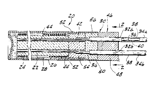
Referring to Figs. 1-2, an electrical heater of the invention,
generally indicated at 20, is shown to include a ceramic core 22
around which is wrapped a helical heating element 24. Surrounding
the heating element 24 and radially spaced therefrom is a tubular
30 metal sheath 26. Insulation material 28 in the space between the
heating element 24 and the sheath 26 electrically insulates the
heating element from the sheath. The insulation material 28 is
- 2100016
preferably magnesium oxide or another particulate insulation
material havlng good thermal conductivity and high electrical
insulation properties at high ternperatures. A closure,
designated generally at 30, closes one end of sheath 26 (its
right end as viewed in Fig. 1). A pair of holes 32a, 32b
extend through closure 30 in a direction generally lengthwise
of sheath 26. The holes 32a, 32b constitute passaging through
closure 30. A pair of bendable power leads 34a, 34b, adapted
for connection to a source of electrical energy, extend
through holes 32a, 32b, respectively. Each power lead
comprises an electrlcal conductor 36, a metallic sleeve 38
around the conductor, and insulation 40 for electrically
insulating the conductor 36 from the sleeve 38. The
conductors 36 may be of stranded or solid wire, but are
preferably of solid wire of a metal (e.g., nickel) suitable
for high temperature use. The insulation 40 comprises a high
temperature dielectric material such as, for example,
magnesium oxide. Each conductor 36 has a terminal portion 42
connected to a corresponding internal lead pin 44. The lead
pins 44 electrically connect the terminal portions 42 of the
conductors to the heating element 24. In the preferred
embodiment, the terminal portion 42 of each conductor 36 is
connected to one of the lead pins 44 by a lapped connection.
To enable the lapped connection, holes are made, as
by drilling, in the outer face of an insulating plug 54, each
hole having its centerline offset from the centerline of the
respective lead pin 44 but laterally bounded by the pin, and
64725-594
2100016
being sized in cross section as to afford closely fitting
accommodation for a terminal portion 42 of the power leads
34a, 34b. The drilling is preferably done at such location on
the plug 54 and to such depth that a portion of the respective
lead pin 44 is removed so that the terminal portion 42 of the
power lead 34a, 34b is received in the hole in overlapping
relation with the lead pin. The insulating plug 54 and the
portion of the sheath 26 around it are adapted to be
perrnanently defor~ned to a reduced cross sectional area upon
being laterally compressed such as by swaging or other
diameter reduction operations. With the terminal portions 42
of the power leads 34a, 34b in the holes and upon the
reduction of the cross sectional area of the insulating plug
54 and the resultant reduction of the cross sectional area of
the holes, the lapped connection is l-nade between the terminal
portions and the lead pins 44 interiorly of the insulating
plug. Moreover, since the centerlines of each opening for the
lead pins and its respective hole for the power leads lie in a
central longitudinal plane of the heater 20 and thus in a
plane of action of the compressive force applied to the
heater, the lead pins 44 and pswer leads 34a, 34b are held in
current transrnitting engagement with each other in radial
orientation with respect to the heater to form the lapped
connections.
The closure 30 comprises a cap 46 having a head 48
~preferably approximately 1/4" thick) and an annular skirt 50
extending endwise frorn the head 48. The skirt 50 has an
overlapping telescopic fit with the open end of the sheath 26.
4a
~ .
~. 64725-594
`- 21 0001 6
While the cap 46 is illustrated as being of one-piece
construction, it wlll be understood that it could be formed ln
more than one piece, as by a metal plug sealingly secured
(e.g. welded) in one end of a metal sleeve or tube.
Preferably the closure 30 is rnade of a gas-impermeable
material reslstant to high temperatures. In the preferred
embodiment, the closure 30 is rnade of a metallic nickel alloy
available from the International Nickel Company, Inc. under
4b
64725-S94
2100016
the trademark Incoloy~. The closure 30 and sheath 26 are sealed
together to seal against the passage of contaminants between the
closure 30 and the sheath 26. The skirt 50 and sheath 26 are
preferably welded together by a weld 52 between the skirt 50 and
5 sheath 26 around the circumference of the sheath 26 to form the
seal. The seal can also be formed by a close sealing pressure fit
between the skirt 50 and the end of the sheath 26. The close fit
is accomplished by laterally compressing the skirt, such as by
swaging, to reduce its diameter to form an inter~erence fit so that
lO the skirt 50 is sealed all around the sheath 26. It is to be
understood that, alternatively, the skirt 50 could be joined to the
sheath 26 by brazing, soldering or gluing, rather than by welding
and/or swaging, provided the closure 30 and alternative seal seals
against the passage of contaminants between the closure 30 and the
15 sheath 26.
The sleeves 38 of the power leads 34a, 34b are also preferably
made of a refractory metal such as 304 stainless steel. The
sleeves 38 have a close interference fit in the holes 32a, 32b
through the head 48 of the cap 46, the fit preferably being formed
20 by a swaging operation on the cap 46 to reduce the cross-sectional
area of the head 48. This results in a corresponding reduction in
the cross-sectional area of holes 32a and 32b so that the head 48
is sealed around the sleeves 38. These interference fits
constitute seals which seal against the passage of contaminants
25 through holes 32a and 32b. The sleeves 38 may also be brazed,
soldered or glued to the head 48 all around the sleeves 38 to
further ensure a gas-impermeable seal. Internal electrically
insulating plugs 54, 56, preferably made of crushable ceramic, fill
the space between the cap 46 of the closure 30 and the end of the
30 ceramic core 22 for electrically insulating the terminal portions
42 of the conductors 36. Leads constructed in accordance with this
invention can withstand temperatures as high as 1800F.
Fig. 3 shows an alternative preferred embodiment of an
2 1 000 1 6
electrical heater similar to the embodiment of Fig. 1 except the
terminal portions 42 of the conductors 36 extend through the core
22 and replace the internal lead pins (designated 44 in Fig. 1).
Fig. 4 shows an alternative preferred embodiment of an
5 electrical heater similar to the embodiment of Fig. 3 except the
closure comprises a metallic plug 100 plugging one end of the
sheath 26 (its right end as viewed in Fig. 4). The plug 100 and
sheath 26 are sealed together to seal against the passage of
contaminants between the plug 100 and the sheath 26. Preferably,
10 the end of sheath 26 is swaged on plug 100 to form an interference
fit and sheath 26 and plug 100 are welded together by a weld around
the circumference of plug 100. Alternatively, plug 100 could be
sealed to sheath 26 by brazing, soldering or gluing.
Figs. 5 and 6 show another alternative preferred embodiment of
15 an electrical heater, generally indicated at 220. The heater 220
is similar to the heater 20 of Figs. 1-2 except the power lead
means of heater 220 has one metallic sleeve 238 surrounding two
conductors 236. For convenience, corresponding parts are numbered
the same as those parts shown in Figs. 1-2 except the prefix "2"
20 has been added to the reference numbers.
The heater 220 includes a ceramic core 222 around which is
wrapped a helical heating element 224. Surrounding the heating
element 224 and radially spaced therefrom is a tubular metal sheath
226. Insulation material 228 in the space between the heating
25 element 224 and the sheath 226 electrically insulates the heating
element from the sheath. A closure, designated generally at 230,
closes one end of sheath 226. Passaging comprising a single hole
232 extends through closure 230 in a direction generally lengthwise
of sheath 226. The sleeve 238 and conductors 236 extend through
30 hole 232. The conductors 236 are adapted for connection to a
source of electrical energy. Insulation 240 within sleeve 238
electrically insulates the conductors 236 from each other and from
sleeve 238. Each conductor 236 has a terminal portion 242
- 2100016
connected to a corresponding internal lead pin 244. The closure
230 comprises a cap 246 having a head 248 and an integral annular
skirt 250. The closure 230 and cap 246 are preferably sealed by
welding and swaging. Also, sleeve 238 is sealed to closure 230
5 preferably by swaging of the closure to reduce the cross-sectional
area of the hole 232.
In the preferred embodiments of this invention, the
arrangements of the closures, sheaths, and seals, seal against the
passage of contaminants into or out of the heater. It is to be
10 understood, however, that the closure could be made of a
gas-permeable material, such as mica or ceramic, without departing
from the scope of this invention.
It is to be further understood that the invention may be
embodied in heaters which contain a heating element of either
15 coiled or other configuration within a sheath, but which do not
utilize a core for support of the heating element.
Also, while the heaters have been shown as being generally
circular in cross section, it is contemplated that the heater may
be of any cross-sectional shape including square or rectangular.
20Moreover, although the power leads 34a, 34b have been
described as having only one conductor 36, it is to be understood
that each power lead could have more than one conductor. The
heater could also have more than one heating element with separate
pairs of conductors for each heating element. Additional leads,
25 such as thermocouple leads, may also be included.
In view of the above, it will be seen that the several objects
of the invention are achieved and other advantageous results
attained.
As various changes could be made in the above constructions
30 without departing from the scope of the invention, it is intended
that all matter contained in the above description or shown in the
accompanying drawings shall be interpreted as illustrative and not
in a limiting sense.