Note : Les descriptions sont présentées dans la langue officielle dans laquelle elles ont été soumises.
~a aP' ~. 1:~. ~~ SC-5247-C
APPARATUS WITH INTERCONNECTION ARRANGEMENT
BACKGROUND OF THE INVEr~ITION
Field of the Invention
The present invention relates generally to electrical apparatus such as
sensors and trans-
ducers and more particularly to an interconnection arrangement for providing
an electrical path
within the material of a support body of the electrical apparatus, the
interconnection arrange-
ment including characteristics to alleviate stresses in the material of the
suppbrt body due to
volumetric changes in the material.
Description of the Related Art
Various electrical components (i.e., devices, element<.~, etc.) are molded
within support
bodies or housings to provide electrical apparatus such as current and/or
voltage transducer.
For example, see U.S. Patent Nos. 5,162,726, 4,002,976, amd 4,935,693.
Commonly, such
support bodies are molded using an elevated temperature-curing polymeric
compound such as
cycloaliphatic epoxy resin. Since the polymeric compound has a different
coefficient of
expansion versus temperature compared to the components molded within, as the
polymeric
compound of the support body cools and cures, forces are e:Kerted on the
various components
with resultant stresses potentially occurring at various points of the
interface between the
2o components and the polymeric material. If such stresses andl forces are not
relieved, undesir-
able stress concentrations can result in the material of the support body with
potentially
deleterious effects. Thus, while it may be desirable to utilize relatively
rigid (i.e., relatively
non-deformable, incompressible) components to accurately position either the
components
themselves or other supported components, such configurations can create
undesirable stresses
in the material of the support body. On the other hand, if flexible (i.e.,
easily deformable,
compressible) components are utilized, then the accurate positioning of
components during the
forming of the support body, within a mold for example, is either impossible,
or greatly
complicated and compromised. To alleviate these problems regarding the support
and posi-
tioning of electrical components, a support arrangement i.<<~ illustrated in
U.S. Patent No.
30 5,162,726 that responds to volumetric changes in the material of the
support body by
permitting relative movement between portions of the support arrangement.
While the prior art arrangements are useful to provide for the relief of
certain stresses
and forces in a molded support body, it would be desirable: to provide
additional and more
economical electrical paths and interconnection arrangements within a molded
support body
~~ ~ !~ ~ SC-5247-C
that both accurately position the electrical path or interconnection
arrangement and that relieve
any stresses due to volumetric changes in the polymeric material of the
support body.
SUMMARY OF THE INVENTION
Accordingly, it is a principal object of the present invention to provide an
electrical
path or interconnection arrangement within a formed support body of polymeric
material while
also providing for the accurate positioning of the electrical path or
interconnection arrangement
within the formed body.
It is another object of the present invention to provide an interconnection
arrangement
including provisions for the grading of the electrical field about a terminal
conductor.
These and other objects of the present invention are efficiently achieved by
the
provision of an electrical path or interconnection arrangement: within a
formed support body of
polymeric material that exhibits volumetric changes during and after the
forming thereof. The
arrangement is useful to provide an electrical path entirely or partially
within the material of
the support body; e.g., to interconnect components within the: material of the
support body, or
to provide an electrical path through the material of the sup~aort body, or to
provide an elec-
trical path from a point on the exterior of the support body to a point within
the material of the
support body such as a connection to a component, etc.
The electrical path or interconnection arrangement provides an accurately
positioned
zo electrically conductive path through the material of the support body and
also responds to,
accommodates, and alleviates the effects of forces at the interface between
the material of the
support body and the electrical path or interconnection arrangement that occur
during and after
the forming of the support body. The interconnection arr;~ngement exhibits
predetermined
deformability/compressibility characteristics to alleviate stresses caused by
the volumetric
changes of the polymeric material.
In a preferred arrangement, the interconnection arrangement includes an
elongated
tubular conductor fabricated from a metallic material. The material, the
thickness of the
tubular walls of the conductor, and the dimensions of the cross-section of the
conductor are
selected in accordance with the dimensions of the electrical path and the
characteristics of the
so polymeric material to provide predetermined deformability/compressibility
characteristics so as
to avoid undesirable stress at the interface of the conductor and the
polymeric material.
In a specific embodiment, the interconnection arrangement also provides for
the
grading of the electrical field about a terminal conductor via the provision
of a resilient
member that is disposed about the terminal conductor and also connects one end
of a conductor
of the interconnection arrangement to the terminal conductor.
-2-
~' ~ ~ SC-5247-C
BRIEF DESCRIPTION OF THE DRAWING
The invention, both as to its organization and method of operation, together
with
further objects and advantages thereof, will best be understood by reference
to the specification
taken in conjunction with the accompanying drawing in which:
FIGS. 1 and 2 are respective front and left-side sectional views of apparatus
illustrating
the interconnection arrangement of the present invention;
FIG. 3 is a sectional view taken along the line 3-3 of l~IG. 1;
FIGS. 4 and 5 are respective front and right-side ele;vational views of a
conductor of
to the interconnection arrangement of FIGS. l and 2;
FIG. 6 is a sectional view taken along the line 6-6 of l?IG. 4; and
FIG. 7 is a rear elevational view, partly in section, of the apparatus of
FIGS. l and 2
and additionally illustrating the incorporation of an additional electrical
device that is
connected to the interconnection arrangement of the present invention.
DETAILED DESCRIPTIOTf
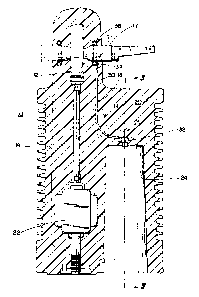
Referring now to FIGS. 1-3 and 7, apparatus 10 has a~n illustrative volumetric
shape for
specific application as an insulator and current/voltage sensor for an
electrical power distribu-
tion switch or the like. The apparatus 10 includes a current-sensing
transformer 12, a support
2o arrangement 14 for the current-sensing transformer 12, a terminal conductor
17 that extends
through the center of the current-sensing transformer 12, and an
interconnection arrangement
18 all contained within a formed body 20. The support arrangement 14 includes
a transformer
assembly 22, which along with a capacitor I6 (FIG. 7) and the interconnection
arrangement 18
provide a voltage sensor of the apparatus 10.
In a preferred embodiment, the components, except :for the capacitor 16, are
molded
into the formed body 20 which is formed in a molding operation from an
electrically insulating
material such as epoxy resin. During the molding operation to provide the
formed body 20, a
receiving cavity 24 is formed. After the molding operation, the capacitor 16
(FIG. 7) is
inserted into the receiving cavity 24, the capacitor 16 is connected to the
interconnection
3o arrangement 18 (as will be explained in more detail hereinafter), and the
cavity 24 filled with a
suitable potting compound to encapsulate the capacitor 16.
As is known to those skilled in the art, it is common and advantageous to use
an
elevated temperature-curing polymeric compound such as c~ycloaliphatic epoxy
resin for the
formed body 20. Since the polymeric compound has a different coefficient of
expansion
-3-
f.a
~,~ t,; ~ SC-5247-C
versus temperature compared to the electrical components, a;s the polymeric
compound of the
support body 20 cools and cures, shrinkage forces are exerted on the
components and stresses
can develop in the polymeric material of the formed body 20 at the interfaces
with the
components. For example, forces are exerted at the interFace between the
interconnection
arrangement 18 and the material of the formed body 20 with the stress being
particularly
concentrated in the areas referred to generally at 19, 21, and :?3.
In accordance with important aspects of the present invention, the
interconnection
arrangement 18, which may also be characterized as a conductor or an
electrical path
providing arrangement, provides the accurate positioning of: the
interconnection between the
to capacitor 16 and the terminal conductor 17 and also relieves stresses that
may develop during
and after the fabrication of the formed body 20. To accomplish this, the
interconnection
arrangement 18 exhibits predetermined deformabilitylcompressibility
characteristics. The term
deformability/compressibility characteristics as used herein refers to the
overall interconnection
arrangement 18 being compressed in an overall volumetric sense while also
being deformed as
to its overall shape and as to certain structural features of the
interconnection arrangement 18
as will be explained in more detail hereinafter. In a preferred arrangement,
the interconnec-
tion arrangement 18 also exhibits resiliency/reversibility characteristics so
that the
interconnection arrangement returns generally to its previous shape and
dimensions after a
volumetric expansion of the material of the formed body 20 ~xcurs. Of course,
it should also
2o be noted that the interconnection arrangement 18 must be relatively rigid
and resistant to forces
that tend to move it out of the defined path, at least to a degree sufficient
to maintain the
desired path during fabrication such as in a molding process.
In a preferred embodiment, the interconnection arrangement 18 includes a
conductor 30
having a tubular elongated shape as best seen in FIGS. l and 4-6. In a
preferred embodiment,
the conductor 30 is oval or flattened in cross-section (FIG. 6) as this
provides for enhanced
compressibility of the conductor 30 as well as the maximunn clearance from
other parts and
boundary interfaces such as the exterior of the molded body 20. Of course, it
should be
understood that the cross-section of the conductor 30 can be round or other
shapes where the
desired compressibility is achieved and the clearance, i.e. distance or
spacing dimension, to a
so boundary surface is not critical and space is available.
The conductor 30 is fabricated from a material that is conductive and also, as
discussed
hereinbefore, deformable/compressible to a predetermined degree as compared to
the stresses
to be relieved in the polymeric compound of the formed body 20 such that the
forces
developed will deform/compress the conductor 30 before any undesirable effects
are caused in
the formed body, i.e. sufficiently deformable/compressible to relieve the
forces to the desired
degree. In this regard, the compressibility characteristic is applicable to
the overall conductor
-4-
.r ~ y~-,, SC-5247-C
30 from an external volumetric perspective regarding the volume of the
conductor 30 within
the formed body 20 while the tubular wall 31 of the conductor 30 is deformable
with respect to
the cross-section of the conductor 30, i.e. the compressibility of the
conductor 30 being
provided due to the space inside the tubular wall 31, which is filled with air
in a preferred
embodiment. Of course, it should be realized that in other specific
embodiments, the space
inside the tubular wall 31 is filled with other compressible materials.
As to the resiliency/reversibility characteristics of the; interconnection
arrangement 18,
if volumetric expansion of the material of the formed support body 20 occurs,
e.g. due to an
elevation of temperature after fabrication and during use, the conductor 30
needs to respond at
to least to a sufficient degree to avoid undesirable stresses in the material
and also to ensure that
no voids are created with respect to the material interface. Accordingly, the
overall conductor
30 as to an external perspective must return to an expanded state as to
overall volume and the
wall 31 must return from its previous degree of deformation to at least some
extent.
Further, the material of the conductor 30, the thickness of the tubular walls
31, and the
dimensions of the cross-section of the conductor 30 are selecl:ed in
accordance with the dimen-
sions of the electrical path and the characteristics of the polymeric material
of the support body
20 to avoid undesirable stress at the interface of the conductor 30 and the
polymeric material.
As stated hereinbefore, the shape of the cross-section of the conductor 30 is
also a factor that
determines compressibility, e.g. the oval shape shown in FIG. 6 being more
easily
2o compressible than a round shape. For example, in a specific. embodiment
where the electrical
path is approximately 5-7 inches, aluminum tubing is utilized for the
conductor 30 having a
wall thickness 31 of .022 inch and a diameter of 3/ 16 inch, before being
formed to an oval
shape. In order to avoid local stress effects at the interface bE;tween the
material of the support
body 20 and the conductor 30, the conductor 30 is coated with a mold-release
agent before the
forming of the support body 20.
The interconnection arrangement 18 also includes a terminal socket 32 (FIGS. 1
and 7)
which is affixed to a first flattened end 33 of the conductor 30 by riveting
or the like. The
terminal socket 32 receives a contact 36 (FIG. 7) of the capacitor 16 for
connection thereto.
In a preferred arrangement, the other end 34 of the conductor 30 is flattened
and formed with
3o a radius of curvature such as an arch or loop, as shown.
In accordance with important aspects of the present invention, a garter spring
38, i.e. a
coil spring in the shape of a torus, is positioned to encircle: the terminal
conductor 17, one
garter spring 38 on either side of the current-sensing transformer 12. The
garter springs 38
are conductive and alleviate the high electrical stresses that occur at the
surface of the material
of the formed body 20 adjacent the terminal conductor 17, i.e. at the
interface therebetween,
thus reducing corona effects. In effect, the embedded garter springs 38 serve
to grade the
-5-
SC-5247-C
~,~~~,'
s
electrical field resulting from the fabricated device configuration. The arch
or loop at the end
34 of the conductor 30 is electrically connected to the terminal conductor 17,
preferably via
the garter spring 38 since it serves the dual purpose of grading the
electrical field and
providing the electrical connection of the conductor 30 to the terminal
conductor 17.
While there have been illustrated and described various embodiments of the
present
invention, it will be apparent that various changes and modifications will
occur to those skilled
in the art. Thus, the present invention encompasses other specific
implementations to achieve
an interconnection arrangement that provides predetermined
deformability/compressibility
characteristics to absorb forces at the interface between the material of a
formed body and the
interconnection arrangement. For example, while a tubular metallic conductor
30 is perhaps
the most economical implementation of the interconnection arrangement 18, the
conductor 30
in other specific implementations is provided by a) tubulaJr members
fabricated from non-
metallic conductive materials or b) non-conductive materials in the shape of
the conductor 30
and additionally including an electrically conductive elongated member 50
(FIG. 6) within the
tubular member 30. Accordingly, it is intended in the appended claims to cover
all such
changes and modifications that fall within the true spirit and scope of the
present invention.
_b_