Note : Les descriptions sont présentées dans la langue officielle dans laquelle elles ont été soumises.
~UU~10
Docket T-285
ADJUSTABLE DAMPERS USING ELECTRORHEOLOGICAL FLUIDS
FIELD OF THE INVENTION
This invention relates to electrorheological (ER) fluid dampers that provide
electronically adjustable damping of a vibrating body.
BACKGROI~ND OF THE INVENTION
Dampers are used in vibration control applications to control resonance. One
such application where dampers are commonly used is as a shock absorber for a
vehicle suspension system designed to control ride and handling of a vehicle for the
comfort and safety of its passengers.
There are several known types of suspension systems that have met with
varying degrees of success. One such system is a conventional passive suspension,
consisting of a passive spring and damper, which must compromise its ability to
control a vehicle. Generally, low damping is preferred for good isolation of noise,
vibration and harshness, whereas high damping is desired for control of body andwheel motion during cornering, acceleration and braking.
Another known type of suspension system is an adaptive suspension, which
utilizes a passive spring and an adjustable damper with "slow" response to improve
the control of ride and handling. The level of damping at all wheel positions can
be selected by the driver, or it can be automatically tuned for variations in vehicle
speed, steering angle, throttle position, brake pressure, or accelerometer signals.
; Still another known type of suspension system is a semi-active suspension,
which is similar to an adaptive suspension, except that the adjustable damper has
"fast" response (less than 10ms) and each wheel position is independently controlled
in real time.
Yet another known type of suspension is a fully active suspension in which
a hydraulic actuator is used in place of the damper to achieve better vehicle control
but at a higher cost.
Theoretically, the performance of a semi-active suspension can approach that
of a fully active suspension at a fraction of the cost. The preferred control
. " ., ,, . . , . ~ .. .. .. .- ; , . ,:. ~ .. .
~lv~
algorithm, known as the "sky-hook" model, consists of a feed-back loop that adjusts
damping level based on (1) the absolute vertical velocity of the vehicle body, and
(2) the relative velocity between the body and the wheel.
A key component of this system is an adjustable darnper with sufficiently fast
response. One means of achieving variable darnping is to use an electro-mechanical
variable orifice to alter the flow rtsistance of a conventional hydraulic fluid.Another means is to use an electrically-charged fixed orifice to change the flowresistance of a field-responsive fluid such as electrorheological (ER) fluid.
The present invention relates to dampers that use suitable ER fluids for
variable damping and which are intended ultimately to be incorporated in a semi-active suspension system. ER fluids, sometimes called "smart" fluids, are materials
having flow properties that can be modified with electric field. This unique
behavior may be utilized to adjust the damping force of dampers/shock absorbers
with fast-acting electronic control by selectively applying voltage to the ER fluid.
Utilizing ER technology in damper applications offers advantages over
conventional technology in that the ER effect is eff1cient, typically requiring only
a few watts of electric power. Also, the damper construction is simplifred due to
the non-mechanical nature of ER technology, potentially decreasing manu-facturing
costs and increasing reliability. In addition, the ER effect provides the fast response
needed for control of a complete semi-active suspension system which consists ofseveral adjustable dampers/shock absorbers filled with ER fluid, power supplies to
energize the fluid, sensors to provide feed-back, and a central comrnand module.The use of ER fluids in damper applications is generally known. However,
there is a need for ER fluid dampers that provide an effective way of tuning thedamping characteristics of the device to suit a particular application. Also, there is
a need for an ER fluid damper package that is especially adaptable for use in anautomobile suspension.
,.' . .. . `'' ' ''' ~ ,, '"' ,"1 "" "~ .. , .
~u~10
-3 -
SUMMARY OF THE INVENTION
This invention relates to ER fluid dampers that provide an effective way of
tuning the damping characteristics of the device to suit a particular application.
Also, the dampers have a unique package arrangement making them especially
adaptable for use in an automobile suspension.
In accordance with one aspect of the invention, the dampers include one or
more annular ER fluid transfer ducts or paths in fluid communication with fluid
cham~ers on opposite sides of the damper pistons. Each fluid transfer path has one
or more contoured surfaces or bands along a portion of the length of one or bothwa11s thereof providing one or more annular constricted working areas through
which the ER fluid is forced when displaced by movement of the pistons. By
selectively applying a voltage/electric field across the primary working areas, the
flow resistance of the ER fluid passing through the primary working areas is
increased which increases the damping force of the dampers.
In accordance with another aspect of the invention, the damping
characteristics of the dampers may be tuned to suit a particular application by
selecting the length or thickness of one or more contoured surfaces to obtain a
desired length or width of the corresponding constricted working area through which
the ER fluid passes.
In accordance with another aspect of the invention, the outer walls of the
annular ER fluid transfer ducts or paths in the dampers are desirably exposed toambient air to promote cooling of the ER fluid passing through such ducts.
In accordance with another aspect of the invention, a one way valve may be
provided in the damper piston to allow a lower jounce force during the compression
stroke than rebound force during the extension stroke without adjusting the voltage
across the constricted working area or areas of the fluid transfer ducts. In a
preferred form of the invention, this is accomplished using a flexible flapper which
closes off a plurality of holes through the piston during the extension stroke and
allows a portion of the ER fluid to pass through the holes during the compression
stroke. The flapper is generally ring shaped including an inner peripheral portion
that is clamped against the piston by a washer and nut arrangement and an outer
i~
, ,., ........ , . : , ., .. .. ~ . . ~ ,. .
-4--
peripheral portion that is free to flex into and out of sealing engagement with the
holes during the extension and compression strokes. A radial flange on the washer
overlies the outer peripheral portion of the flapper to limit the arnount of flexing of
the flapper away from the piston for extended flappPr life.
In accordance with another aspect of the invention, a small bleed hole may
be provided in the damper piston to diminish the friction-like effect of the ER fluid
in the firm damping mode whenever there is a change in direction of the piston.
In accordance with another aspect of the invention, the dampers may include
a single ended rod extending axially outwardly from one side of the piston, and a
pressurized gas reservoir in fluid pressure communication with the ER fluid acted
upon by the other side of the piston to take up the fluid volume displaced by the
piston rod and thermal expansion. A floating piston is desirably used to isolate the
pressurized gas reservoir from the ER fluid. Alternatively, a flexible diaphragm may
be used for that purpose. Also, a reservoir of ER fluid may be provided between
the piston chamber and gas reservoir, with an orif~ice in a partition separating the
piston chamber from the ER fluid reservoir to produce a large pressure drop across
the orifice during the compression stroke which reduces the amount of pressure
needed in the gas reservoir. A one way valve in the partition provides for free flow
of ER fluid from the ER fluid reservoir to the piston charnber during the extension
stroke.
In accordance with another aspect of the invention, the gas reservoir may be
replaced with a pressurized reserve tube of ER fluid to take up the ER fluid volume
displaced by the piston rod and thermal expansion.
To the accomplishment of the foregoing and related ends, the invention, then,
comprises the features hereinafter fully described and particularly pointed out in the
claims, the following description and the annexed drawings setting forth in detail
certain illustrative embodiments of the invention, these being indicative, however,
of but several of the various ways in which the principles of the invention may be
employed.
BRIEI~` DESCRIPTION OF THE DRAWINGS
In the annexed drawings:
:, ~ ...... .. . ... .. .
. , .. , .. ..... , , ., . , .. ,, ;
,~ t Vi)~10
:
Fig. 1 is a schematic longitudinal section through one form of ER fluid
damper in accordance with this invention which includes a single annular ER fluid
transfer duct surrounding the piston chamber;
Fig. 2 is a fragmentary schematic longitudinal section through the head end
5 which is opposite the rod end of an ER damper in accordance with this invention
which may be substantially the same as that shown in Fig. 1 except for the use of
a flexible diaphragm in place of the floating piston;
Figs. 3 and 3A are fragmentary schematic longitudinal sections through the
head end of other ER dampers in accordance with this invention which may be
10 substantially the same as that shown in Fig. 1 (or Fig. 2) with the addition of a
reserve reservoir of ER fluid between the piston chamber and gas reservoir;
Figs. 4 and 4A are schematic longitudinal sections through still other ER
dampers in accordance with this invention which include a pressurized reserve
chamber of ER fluid instead of a separate pressurized gas reservoir of any one of
15 the dampers of Pigs. 1-3 and 3A;
Fig. 5 is a schematic longitudinal section through yet another form of ER
damper in accordance with this invention including modified duct walls;
Figs. 6 and 6A are fragmentary longitudinal sections through the duct walls
of other forms of ER dampers in accordance with this invention showing different20 duct wall configurations;
Fig. 7 is a schematic longitudinal section through still another form of ER
darnper in accordance with this invention which includes a plurality of ER fluidtransfer ducts surrounding the piston chamber;
Fig. 8 is a fragmentary schematic longitudinal section through the duct walls
25 of another form of ER damper in accordance with the invention including a plurality
of ER fluid transfer ducts, similar to Fig. 7, but with a different duct wall
configuration;
Fig. 9 is a schematic longitudinal section through still another form of ER
damper in accordance with this invention which includes an insulated electrode in
30 the ER fluid transfer duct;
.. . . .. - , ` . :.. . , i , , , , , ~ . . . . . . . . . . . . .. .. .
: . ~ . ,, . .. .~ . . . . . .. .. .
0
-6-
Fig 10 is a fragmentary longitudinal section through yet another form of ER
damper in accordance with this invention which may be substantially the same as
any of the ER dampers shown in Figs. 1-9 and including one or more one way
valves in the damper piston;
Figs. 11-13 are enlarged fragmentary longitudinal sections through other
forms of damper pistons in accordance with this invention having one or more oneway valves therein which may be incorporated in any of the ER dampers shown in
Figs. 1-10;
Fig. 14 is a fragmentary schematic longitudinal section through another form
of ER damper in accordance with this invention which may be substantially the
same as any of the ER dampers shown in Figs. 1-9 and including a bleed hole
through the damper piston; and
Fig. 15 is an enlarged fragmentary longitudinal section through another form
of damper piston in accordance with the invention having one or more one way
valves and bleed holes through the piston which may be incorporated in any of the
ER dampers shown in Figs. 1-10.
DETAILED DESCRIPTION OF THE PREFERRED EMBODIMENTS
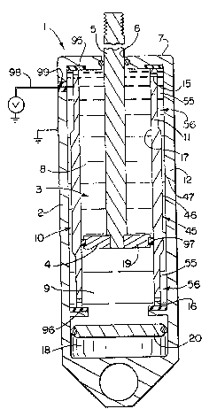
Referring now in detail to the drawings, and initially to Fig. 1, there is shownone form of adjustable damper 1 using ER fluid in accordance with the invention
including a housing 2 containing a piston chamber 3 in which a piston 4 is axially
slidably received. Relative movement of the piston 4 within the piston chamber 3occurs when oppositely acting forces are applied to the damper housing 2 and piston
rod 5 which extends outwardly from the piston through a sealed opening 6 in the
rod end 7 of the damper housing.
The piston 4 divides the piston chamber 3 into two fluid chambers 8, 9 which
are in fluid communication with each other through one or more annular fluid
transfer ducts or paths surrounding the piston chamber 3. One such fluid transfer
duct 10 is shown in Fig. 1, formed by providing an inner cylinder 11 radially
inwardly spaced from an outer cylinder 12. Outer cylinder 12 is desirably an
integral part of the exterior housing 2 to promote cooling of the ER fluids, which
are relatively heat sensitive, when pushed through the duct as described hereafter.
.1,
~ i . , .. .,. , , . . . , ... .. ,, ,, ., . . ". , .,,.,,,.. ,., .. , ... .. ~. , ,, . - .
~ i U ~
-7-
Radial holes or channels 15, 16 adjacent opposite ends of the inner cylinder 11
provide unobstructed fluid flow between the ends of the fluid transfer duct 10 and
the respective fluid chambers 8, 9. Such radial holes or channels may be provided
in the ends of the inner cylinder 11 as shown or in insulators 95, 96 at the ends of
the inner cylinder 11 as desired to permit unobstructed fluid flow between the ends
of the fluid transfer duct 10 and the respective fluid chambers 8, 9.
The irmer wall 17 of the irmer cylinder 11 desirably forms the piston
chamber 3 in which the piston 4 is axially movable. Both the piston chamber 3 and
fluid transfer duct 10 are filled with a suitable ER fluid which is pushed through the
fluid transfer duct from one end of the piston chamber to the other by the motion
of the piston. The fluid volume displaced by the piston rod S and by thermal
expansion may be accommodated by a pressurized gas reservoir 18 in fluid pressure
communication with the fluid charnber 9 acted upon by the side 19 of the piston 4
opposite the piston rod 5.
In the embodiment shown in Fig. I, a floating piston 20 is provided between
the piston chamber 9 and reservoir 18 for isolating the reservoir 18 from the ERfluid, whereas in Fig. 2 a flexible diaphragm 21 is substituted for the floating piston
20. However, the floating piston 20 is preferred over the flexible diaphragm 21 for
increased durability. Also, a reservoir 22 of ER fluid may be provided between the
fluid chamber 9 and gas reservoir 18, formed by providing a partition or wall 23 in
the housing 2 between the fluid chamber 9 and gas reservoir 18 as schematically
shown in Fig. 3.
Extending through the wall 23 of reservoir 22 is an orifice 24 which
produces a large pressure drop across the wall during the compression stroke, thus
reducing the amount of pressure needed in the gas reservoir 18 to prevent the ERfluid pressure in fluid charnber 8 from dropping below atmospheric. A one way
valve 25 in the wall 23 provides for free flow of ER fluid from the reservoir 22 to
the fluid chamber 9 during retraction of the piston 3.
The one way valve 25 shown in Fig. 3 is a spring-loaded ball valve 26
mounted within a hole 27 in the reservoir wall 23, whereas the one way valve 25'shown in Fig. 3A is a flexible flapper 28, which may be made of a suitable metal,
.
, , ,~, l , - ..
-8-
rubber or plastic. The inner periphery of the flapper 28 is retained in place against
the axial inner side of the partition 23 by a retaining washer 29, leaving the outer
periphery of the flapper free to flex into and out of sealing engagement with the
partition 23 respectively to close and open one or more holes 27 therethrough.
Otherwise, the damper shown in Fig. 3A is substantially the same as that shown in
Fig. 3.
The gas reservoir 18 may be filled with an inert gas such as nikogen, but is
preferably filled with a gas such as sulphur hexafluoride that has a high break-down
potential to avoid arcing problems if the gas should leak into the ER fluid. Theamount of gas charge must be greater than the maximum pressure drop expected
across the piston 4 in order to prevent the ER fluid from cavitating during jounce
(compression) and also prevent air from being drawn past the sealed opening 6 and
into the piston chamber 3.
An alternative to the floating piston 20 and flexible diaphragm 22 type
accumulators shown in Figs. I and 2 is to contain the gas charge in a reserve
chamber of ER fluid. Fig. 4 shows one such form of damper 30 in accordance with
the invention in which an intermediate cylinder 31 is mounted between the irmer and
outer cylinders 32, 33 thus dividing the space between the inner and outer cylinders
32, 33 into an ER fluid transfer duct 34 (between the inner and intermediate
cylinders 32, 31) and a reserve chamber 35 (between the intermediate and outer
cylinders 31, 33). The reserve chamber 35 accommodates the fluid volume
displaced by the piston rod 36 and by thermal expansion through openings 37
adjacent one end 38 of the intermediate cylinder 31 which communicate with the
fluid transfer duct 34. The ER fluid within the reserve chamber 35 is maintainedunder pressure by a gas charge 39 in the other, closed end 40 of the chamber.
If desired, a partition 41 may be provided between the head end of the piston
chamber and the reserve chamber 35 of ER fluid, with an orif~ce 42 and one way
valve 43 in the partition as schematically shown in Fig. 4A. The orifice 42 provides
a large pressure drop across the partition 41 during the compression stroke thusreducing the amount of gas charge needed in the closed end of the reserve chamber
35 to prevent the ER fluid pressure in the rod end of the piston chamber from
,., -,
~v~10
-9-
dropping below atmospheric. The one way valve 43 provides for free flow of ER
fluid from the reserve chamber 35 through openings 37 in the intermediate cylinder
31 and one way valve 43 to the head end of the piston chamber during retraction of
the piston.
One or both walls of the fluid transfer duct are contoured along a portion of
the length thereof to provide a relatively narrow gap which constitutes the primary
working area for the ER fluid when voltage is applied across the duct to increase
its resistance to flow through the primary working area as described hereafter. In
the damper design 1 shown in Fig. 1, the primary working area 45 in the duct 10
is formed by a single band 46 on the inner wall of the duct which defines with the
outer wall of the duct a relatively long, narrow gap 47 therebetween. In like
manner, in the damper design 30 shown in Fig. 4, the primary working area 48 in
the duct 34 is formed by a single band 49 on the inner wall of the duct which
defines with the outer wall of the duct a relatively long, narrow gap 50
therebetween.
By way of example, the damper 1 shown in Fig. I may have an ER fluid
duct 10 with an effective length between the openings 15, 16 at the ends thereof of
approximately 7 inches and a gap 55 in the non-working areas 56 having a width
of approximately .060 inch. Intermediate the length of the duct 10 is the band 46
which has a length of approximately 5 inches and a height of approximately .040
inch, leaving a gap 47 in the primary working area 45 having a length of
approximately 5 inches and a width of approximately .020 inch. However, how
long and how wide the gap 47 is in the primary working area 45 are variables in
tuning the duct geometry which may be selected to tailor the damping characteristics
of the damper to suit a particular application. Also, while the band 46 is shown in
Fig. 1 intermediate the length of the duct, the band may be located anywhere along
such length as desired.
Likewise, a plurality of axially spaced apart bands 57 may be provided along
the length of the duct 58 of an ER damper 59 as schematically shown in Fig. 5 toform a plurality of primary working areas 60 having a combined length equal to or
different than the single primary working areas shown in Figs. 1 and 4 to obtain the
'. . ~ : . .. .
~ I vd~10
-lo-
same or different damping characteristics as desired. Also, one or more bands 61may be provided on the outer wall of the ER fluid transfer duct 62 as shown in Fig.
6 rather than on the inner wall of the ducts as shown in Figs. 1, 4 and 5.
Alternatively, one or more bands 63 and 64 may be provided on both the outer andinner walls of an ER fluid transfer duct 65, with the bands axially spaced or axially
aligned as schematically shown in Fig. 6A.
More than one fluid transfer duct may also be provided in the ER fluid
damper to increase the cross sectional flow area for the ER fluid for a given length
of damper, with contoured surfaces along portions of the lengths of the ducts to tune
the datnping force. One such damper 70 is shown in Fig. 7 which includes two ER
fluid transfer ducts 71 and 72 surrounding the piston chamber 73 formed as by
providing an intermediate cylinder 74 between the inner and outer cylinders 75 and
76, with openings 78 and 79 at either end of the intermediate cylinder 74 similar to
the openings 80 and 81 at either end of the inner cylinder 75. In Fig. 7, a single
band 82 and 83 is provided on the inner wall of both ducts 71 and 72. However,
all of the bands 84 and 85 for two ducts 86 and 87 may be provided on opposite
walls of an intermediate cylinder 88 between inner and outer cylinders 89 and 90as schematically shown in Fig. 8. Alternatively, one or more bands may be
provided on one or both walls of both ducts in the manner previously described.
The size of the bands in each duct may be the same or different as desired.
The length and height of each of the bands or other duct wall contours may
be varied as desired to provide gaps of different lengths and widths in the primary
working areas to achieve the desired damping characteristics. In the various figures,
the bands are shown as having uniform heights throughout their lengths except attheir ends which are desirably sloped at an angle away from each other to eliminate
any sharp corners (having included angles for example of 90 or less) which could
cause turbulent flow through the ducts and a concentration of the electric field at the
corners possibly causing arcing when a voltage is applied across the primary
working areas as described hereafter. However, the bands could also be of varying
heights along their lengths for different applications if desired.
' . ` ~, ,' ~ '.'.. ` . ' ' ' ' ' ` ` ,
~u~210
In the damper I shown in Fig. 1, the inner cylinder 11 is electrically
insulated from the outer cylinder 12 by providing insulator rings 95, 96 between the
ends of the inner cylinder 11 and the adjacent housing support surfaces. Also, the
inner cylinder 11 is electrically insulated from the piston 4 by a plastic bearing 97
around the outer diameter of the piston which forms a fluid seal with the inner
diameter of the iMer cylinder 11. A voltage source V is applied across the annular
duct 10 by cormecting a lead 98 from the voltage source directly to the inner
cylinder 11 through an insulator 99 in the outer cylinder 12 and by grounding the
outer cylinder as shown.
The inner cylinders of the dampers shown in Figs. 4, 5 and 9 may be
similarly electrically insulated from the outer cylinders (and in the case of Fig. 4,
also from the intermediate cylinder) as well as from the pistons. Also, the voltage
source may be similarly applied to the inner cylinders through suitable insulators in
the outer cylinders (and in the case of Fig. 4, also in the intermediate cylinder), and
the outer cylinders may be suitably grounded.
In the damper 70 arrangement shown in Fig. 7, which includes two ER fluid
transfer conduits 71 and 72, the inner cylinder 75 is electrically connected to the
outer cylinder 76, which is in turn connected to ground. The interrnediate cylinder
74, on the other hand, is electrically insulated from both the inner and outer
cylinders 75 and 76 by placing insulator rings 100 and 101 at the ends of the
intermediate cylinder, and a voltage source is connected to the intermediate cylinder
74 by a lead 102 extending from the voltage source to the intermediate cylinder
through an insulator 103 in the outer cylinder 76.
When a voltage is applied across each of the annular ducts, an electric field
is created perpendicular to the fluid flow, which causes the ER fluid to substantially
instantly increase its resistance to flow through the primary working areas of the
ducts. This causes an increase in pressure drop across each of the damper pistons
which increases the force required to move the pistons.
When no voltage is applied across the ducts, damping is due entirely to the
viscosity of the ER fluid and is proportional to its flow rate through the ducts.
However, when a voltage i~ applied across the primJry worlcing rreas ol~ the duc~s,
l. ~ - - , . ~ , ,
~ ; ;, ;, , , . . , ~.: .
the field-induced stress of the ER fluid substantially instantaneously increases the
resistance to flow of the ER fluid through such primary working areas and thus the
damping force required to move the pistons. This damping force can easily be
adjusted to different values by changing the voltage applied to the ER fluid.
S In the various damper designs previously described, the applied voltage also
produces some electric field across the non-working areas of the ducts which causes
some additional resistance to flow in the non-working areas due to the ER effect.
However, this effect can be minimized by making the width of the gaps in the
primary working areas substantially less than that in the non-working areæ, for
example, one third the width of the gaps in the non-working areas or less.
Moreover, the resistance to flow in the non-working areas 104 of a fluid transfer
duct 105 of an ER damper 106 due to ER effect can be substantially completely
eliminated by providing an insulated electrode 107 only in the primary working area
108 of the duct to substantially confine the electric field to the primary working area
when a voltage is applied to the insulated electrode by means of a lead 110
extending through an insulator 111 in the outer cylinder 112 of the duct as
schematically shown in Fig. 9.
When the dampers are used in a vehicle suspension system design, it is often
desirable to have higher darnping force in rebound (extension) than in jounce
(compression). To decrease the jounce damping force relative to rebound without
having to adjust the voltage, a one way valve 115 may be included in the damper
piston 116 as schematically shown in Fig. 10. During jounce, the valve 115 allows
some fluid flow through an orifice 117 in the piston, thereby reducing the totalresistance to flow and reducing the pressure drop across the piston.
The construction of valves for ER fluid dampers as opposed to conventional
hydraulic fluid dampers is complicated by the presence of fine particles that are
generally dispersed in ER fluid.
If required by a particular application, the one way valve 115 may be spring
loaded to provide pressure relief at a predetelmined desired level of pressure drop
across the piston. The valve 115 shown in Fig. 10 is a spring loaded ball valve,whereas Fig. 11 shows a spring loaded washer 118 as the one way valve. The valve
` ' ~, ` ', " ~, '............... '.' ' .. ' . ' ' ' ~, " ' ' `
. .. ~ .
, . . .. ' ` ~ ' : ` ` . ` ' ` :
3 2 ~ ~
-13-
washer 118 is slidably received on the piston rod 119 arld is urged into engagement
with the extension side of the piston 120 by means of a coil spring 121 to close off
one or more holes 122 through the piston during the extension stroke. During thecompression stroke, the valve washer 118 is forced away from the piston by the
S pressure in the head end of the piston chamber, allowing a portion of the fluid to
pass through the holes 122 to the rod end of the piston charnber. A retaining ring
123 retains the coil spring 121 in place on the piston rod.
Fig. 12 shows another form of one way piston valve 124 which comprises
a flexible metal flapper 125 having its inner periphery 126 pressed up against ashoulder 127 onthe piston rod 128 by the piston 129 and secured in place by a nut
130 threaded onto the end of the piston rod. The outer periphery 131 of the flapper
125 overlies one or more holes 132 in the piston and is free to flex away from the
holes during the compression stroke.
Fig. 13 shows still another piston valve 135 in the form of a flexible flapper
136 having an outer periphery 137 which moves into engagement with the piston
138 to close off one or more holes 139 therethrough during the extension stroke as
shown in solid lines and flexes away from the piston to allow a portion of the fluid
to pass through the holes during the compression stroke as shown in phantom lines.
The inner periphery 140 of the flapper 136 is clamped against the extension side of
the piston by a washer 141 pressed up against a shoulder 142 on the piston rod 143
and held in place by a nut 144 threaded onto the end of the piston rod. The outer
periphery 137 of the flapper 136 overlies the holes 139 in the piston and is free to
flex away from the holes during the compression stroke. A radial flange 145 on the
washer 141 overlies the outer periphery of the flapper in axially spaced relation from
the piston to limit the amount of flexing of the flapper away from the piston for
extended flapper life.
During movement of the damper pistons in the "firm" mode, which occurs
when a voltage is applied across the ER ducts, an abrupt change of force occurs
whenever there is a change in the direction of movement of the pistons. This
characteristic is typical of a friction damper and is considered undesirable for a
vehicle suspension system since it contributes to harshness. The friction-like
... . . .~ . . , .. .. ,.... ,., .. .~ , .. . .
~lu~2-~ 0
-14-
behavior is due to the ER fluid exhibiting, in the presence of an electric field, an
additional stress component that may be modeled as a yield stress. This problem
can be alleviated by continuously adjusting the electric field using an appropriate
controller. However, this adds complexity to the system controller. Likewise, this
problem can be alleviated by installing rubber bushings at the damper attachmentpoints to absorb harshness. However, the spring rates of the bushings add a delay
to the system response.
A solution to the problem which requires no moving parts or additional
hardware and does not add any delay to the system response is to provide a smallbleed hole 150 in the damper piston 151 as schematically shown in Fig. 14 to
dimini.sh the friction-like effect of the ER fluid whenever there is a change indirection of the piston. Such a bleed hole may be provided in the piston in addition
to or in lieu of the piston valves shown in Figs. 10-13.
Fig. 15 shows one form of damper piston 152 in accordance with this
invention including both a one way valve 153, which may be similar to the one way
valve 135 shown in Fig. 13, and a bleed hole 154 and/or 155 in the piston. The
bleed hole 154 is shown located radially outwardly of the flexible flapper 156,
whereas the bleed hole 155 is shown in axial alignrnent with a hole 157 through the
flapper 156. In either case the bleed hole 154 and/or 155 in the damper piston 152
will remain open at all times for diminishing the friction-like effect of the ER fluid
regardless of the change of direction of the piston. A disadvantage to providingsuch a bleed hole is that the maximum damping force of the damper is reduced.
Although the invention has been shown and described with respect to certain
preferred embodiments, it is obvious that equivalent alterations and modifications
will occur to others skilled in the art upon the reading and understanding of the
specification. The present invention includes all such equivalent alterations and
modifications, and is limited only by the scope of the claims.
. " . . : ~ .: ,
" ~ .
,~ . ........... ,,~ .
.. . . . . . .