Note : Les descriptions sont présentées dans la langue officielle dans laquelle elles ont été soumises.
CA 02101467 1999-04-21
Background of the Invention
Mirrored ceiling and wall surfaces are decoratively
appealing, but prior to my United States Patent No. 4,990,407
they presented structural and construction problems. As noted
in that patent, if the mirror is to be glass, as is generally
preferred, weight is a significant disadvantage, particularly
in ceilings where it is difficult to handle large glass panels
during installation and difficult to provide adequate
structural support. Smaller glass mirrors, in the form or
size of tiles, reduce the weight problem of each individual
piece, but at least two significant problems remain. First,
glass mirrors are not good acoustical absorbers, and therefore
yield higher than necessary sound levels where used. Second,
glass mirrors generally crack under heat and heretofore have
been unacceptable where fire-resistant construction is
desirable.
Another important objective of my earlier patent is
personal safety. Conventional glass mirror installed in
direct hung gridwork presents a possible safety hazard if
impacted by a mop frame or other implement. In glass industry
usage, a shatter-resistant mirror is the term
- 2 -
63285-1052
0'1-?8-9~ !G;e:a n~'~t F~!OW s.~i ~, ~, ~~.~~.~~i'~~ a
P
used when a vinyl or other supporting shesxt is adha~al.vely
~:eourad to the back surface of a mirror, but suoh a structure
hsips to prevent shards of glaer~ from falling from the mirror
mores than preventing the glass Erom rohatt~ring.
Tlte overriding puree~e of a mirror tile is decorative
and say invention in my prior patent made mirror tilao aon_
~structad of glees sale and psaotica,Z. Fag oommcarcially sold
under the names Image-SaE~arH, Tru-kdirrorTH and Teland Raflao- ,
tionsra, trademarks of Inter-County Building Ntatariale Corp.
of oawr park, Long zaland, Naw York, ~uch til~s hove been
approved under building codas and have received Underwriters
Laboratories Ino. (u.L.~) approval.
Notwithstanding th~ purpose of my prioa~ inv~ration to
make glass tiles safer (resisting breakage but if
aeeid~ntally broken, the glass fragments remain in place),
there is decorative purpose in having glass mirror tiles
which are intentionally cracked. There is grout visual '
b~auty in a well-silvered glass mirror which ie intentionally
oraoked or oraxed thrpughout. Tlaa pr~eant i~xve~ntion provides .
a structure mnd method of making such t h em, and providing
them with adequate protaation when install~d»
Rut the invention hue a broader use than the opeoific
purposre above desoribed. 7tn its broad prinoiple, the
inv~ntion provides a d~corativs craokad glar~ laminate Ira
various lorrap auoh as tilenro, panels, ah~ats, plataea, veneers
dnd ~ applioationa. Th~ intarauediate layer of the
G7-'?$-~a 1(':''_'3 API Fnt~M ~. ~l, F. ~;. ?1?
r
laminate ie a sheet of tempered glass m:lrror. Thi~
interraodiato layer is laminated between a supportive or
protective backing such as a fiberboard panel, and an outer
(front) transparent shaa~t, e.g., s sheet of annealed glee~.
mhe intormadiate tempered glass u~irror is caused to crack
E~om edg~ to e~dg~ by cutting into one edge, as by a rotating
diamond-tipped bia~de.
The renultinrl laminate may ho a~ad as a aaillng Glla, a
i'loor tile, a wall decoration, a table or counter tap, and
various othos applications.
-a-
# . . ,. .,' . . ,
' ~
'
~~~ .~,~ .. ~. , .-.;... :, ':. "' ~ '
.j '.
CA 02101467 1999-04-21
Summary of the Invention
The present invention accordingly provides a mirror
construction which combines the visual advantages of an
intentionally cracked glass mirror (distortionless reflected
images, high resistance to discoloration due to aging or
exposure to light or atmospheric attack) with none of the
safety disadvantages of a conventional installation of glass
and with high degrees of fire-resistance and acoustical
absorption, in sizes and shapes adopted for ease of shipping,
handling and installation.
More specifically the invention provides a
decorative laminate, comprising a. a front light-transmitting
sheet, b. a backing sheet, and c. an intermediate
decoratively cracked glass sheet between said front and
backing sheets, d. said front, backing and cracked glass
sheets being laminated together, forming a unitary laminate.
The invention also provides a ceiling tile
composite, comprising a. glass mirror means and mineral
fiberboard backing means laminated thereto, b. suspension
means, said suspension means comprising gridwork means
comprising ceiling tile composite supporting web means, c.
mineral fiberboard backing means having at least one recess to
receive at least a portion of said supporting web means, d.
said glass mirror means having edges at least one of which is
chamfered.
From another aspect, the invention provides a method
of making a decorative cracked glass laminate, comprising the
steps of: a. laminating together a front light-transmitting
sheet, a backing member, and an intermediate glass sheet
63285-1052
CA 02101467 1999-04-21
sandwiched between said front light-transmitting sheet and
said backing member, and b. causing said intermediate glass
sheet to crack throughout at least some of its area.
To illustrate, the product of the present invention
comprises a laminate of a glass mirror and a glass cover with
a transparent adhesive laminating layer in between. The glass
laminate is itself bonded to a support member, which for
ceiling tile use is preferably a water-felted mineral
fiberboard panel. The glass mirror layer is intentionally
cracked or crazed in accordance with the method hereof for
visual decorative purposes. Because the cracked mirror layer
is sandwiched between the mineral fiberboard or other support
and the untracked glass cover, the otherwise sharp surface
edges of the cracks are not exposed.
Alternatively, the intermediate layer may comprise a
non-reflecting cracked glass sheet and the backing layer may
comprise a mirror further backed, where needed, by a shock and
heat retardant backing such as a mineral fiberboard.
For flooring use, the glass laminate is set in a
polymer material, which flows around the laminate and then
cures or hardens to encapsulate the laminate, thereby
supporting and protecting the laminate.
A method of the present invention comprises (a)
tempering a glass mirror, (b) annealing a glass sheet, (c)
laminating the glass mirror to the glass sheet by means of a
vinyl laminating layer, preferably polyvinylbutyral, (d)
bonding the glass laminate of step (c) to a backing board,
such as a water-felted mineral fiberboard panel, with the
glass mirror being sandwiched between the backing board and
- 6 -
63285-1052
CA 02101467 1999-04-21
the glass sheet, and (e) touching an exposed side edge of the
glass mirror layer with a rotating diamond-tipped blade such
as a rotary saw or grinding wheel to crack or craze that layer
in situ.
- 6a -
63285-1052
0"-..%6-93 i0; 23 khi aRG!! S. N'.. P, 'f, ~ ~. ~. ~ i~ ~ ?15
r
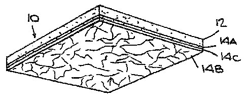
De~c~. of the Q~~,wsna
figure 1 is a perspeaeive view o~ a cracked cilass
tailing tile of the present invention.
figure 2 is an enlarged Fragmentary side view uf~the
arao$~d glaso ailing tile of the pr~uent invention,
Bigurw 3 is an explodud vi~w of the cracked glass '
aeiling tile of th~ pres~nt .invention, showing the layers of
the glass latainate partly broken away Por clarity.
Figure 4 ie an edye viww of the oraakad glass ceiling
tile oP the present invention shown supported on hung
gridwork.
Ci-28-,';~~ 'L~;2;5 A?~ FPOI~d ~.~il, P. u, ~' ~ p~F,
r
Figure 9 ie nn onlarg~d fragmentary aids view of the
creaked glasxe ceiling tile o! the present invention s3howing
the diamond-tipped rotating blad~ touching a aide edges uP the
glaarss mirror layer, causing tho same to crack or crazes.
Figure 1o nhowe thm ora4kod glass ceiling tilo of the
pras~ent invention in a cxidcs view, mupportod by a concealed
grid,
Figure 11 shown t.ho ara.kad g p,~a Qailing tile of the
pressent invention in aide viaw, supported by a recesssed
expae~d grid.
Figures 12 is a fragnesatary vertical section through an
embodiment o! the invention used fox pleat or counter-top
,
appliaationa. ,
Figure 13 is a fragmentary vertical section ~ahowing the
u6s8 of o temporary data to form a recess in a 2luor, or
gaunt~r-~tap lar the decorative glees laminate and a pourable
polymer which oncapaulnt~s the laminate and embeds 1n the
reeaaam.
Figur~ 14 ie a aside edge view of a cracked glass wall
tile or panel made in aaaordance with the present invention.
Figure iS is an edge view o! anath~r emtrodiment of the
invention wherein the intermediat~ layer ie a cracked non-
ratl~ating glaas~s sheet and the backing layer ie a mirror.
Figur~ 16 ie a view similar to Figur~ W , but showing an
additional backing applied to th~ nsirrorr said additional
booking providing anti-shook and heat retarding propertiar~.
s
J'1-26-9? 1~7:'?' At~t FROM S, try, F. r. '~'~ ~ (~ ~ pl7
P
12~t~rriationP afer~,~ Pi i'o~.lN~l~ .
Ref~rring to zhe drawing, t:ha oeiling tile composite 10
of the present invention is a decorative structural oloment
comprising in banded combination r~hao)c retardant n sane 12,
Eor ceiling tile ue~, prQferably minarnl fib~rboard,
decar~ative moans la and bonding means 16, prat~rably an
adhesive, therebetwoon.
A.s indioated in my prior pata~nt, mineral fiberboard 12
is preferably a water felt~d mineral composition aaouatioal
ceiling panel having speciYic charactaristicS oP at least one
substantially planar but fissured surfac~ 18, a minimum
donaity o1 approximately one pound per sguare Foot of area
covexed in order to oomply with Underwritera~Laboratori,es
Inc. (U. L. Lobe) classiYied acoustical material time design
Eire to~ts, and oomplianae Nith other fir~ ratin~ls. The
Eleeur~W on ar in said surface 18 ar~ preLerably uniform and
non-directional.
Acceptable no~amerafally-availablm gaineral fiberboards
gor uge with th~ present invention are USG Auraton~a~r
FireoodeT~ panols in Omni-E~iseur~d pattern (Unit~,d States
Gypsum Company, Chicago, Illinois), Armstrong Minaboard'"
Bireciuard panel~r, Cortege putt~rn (Armstrong World
Industries, Ins., Lanaagtor, penneylvania) and cr~lotexTN ,,
Hyton~~ Prot~ctcnaTp panels, Mosaio or ND Fiss.uretone
psttexna~ (colotes Building Products Division, The Celntex
Corporation, lamps, Florida).
_8_
D?-23-9? ~G:23 P,ad FkGM ~, M, F. F~. PIB
P
Decorative means 1q prs~farably comprises a glas~ mirror
layer 14a, a glass cover .layer 14s and laminating means 14c
thc~rebgtwedn. class mirror layer the is praPerably a daubla-
thiok decorative glass having a nominal thicDcnass of 1/e
inch. other thicknesses, or color=tinted glass, may bs used
depending on availability, application and desired dmoosative
etteat. Glass itself is non-combustible. Tn accordance with
the pr~sent invention, the glass of glfles mirror layer 14p is
temp~red, preferably full t~mpered and not just heat
str~ngthoned, as generally understood in the glass industry,
Also in accordance with the present invention, the glass of
glass ppver layer 14e is annealed as genere~l.ly undareLood in
the glass industry. Tampered glass mirror layer 14e and
annealed glees cover layer 1qs acs joined by an intermediate
laminating means 19c which may be a transparent vinyl. The
vinyl is either clear or color tinted as may b~ desired.
Folyvinylbuterol im a preferred material whioh fu~es to the
adjaa~nt glass surfaces rather than having s~parate
adh~sivas. A suitable commercially available
polyvinylbuterol lamination resin is Staflexd Opticalor~ from
Monsanto, available in color. Alternatively, a liquid glass
lamination resin may b~ used, auah a~ plaoid/Glycol
aondanaate with a methyl a~tteyl ketone perioxidacatalyst, with
Organasilana esker (Gamma-M~thacryloxypropyltrimsthoxysilana)
adhesion promoter. Such a resin is clear: transparent
pigmentation racy b~ added.
Dgaorativ~ means 14 of the present invention tlsurr far
hbs two unarrroked glass layers, tempered glass mirror layer
lqa mnd anndalsd glass aovgr layer 14c, join~d by
irtta~rm~dlatas lamlnatlng rosuns 14c. 'fhe glees mirror 14a side
oP Aecorative m~aner 14 in turn io bonded to min~ral
tib~rbo4r4 12 by bonding means 16 to form ceiling tile
aompoeite 10.
-1p_
!:~~-%3-9? IG;2.s A!~I F~'.ON t. hl,F.'.a. ~~ ~~.~~ ~~ rl9
r
As indicated in day prior patent, bonding m~ans 16 camprisas
an adhesive, pre!~rably a rubber- or latex-base epoxy
waterproof composition, Which is non-flammable when fully
our~d and which is adapted Eox mirror a~e ao ae to be non-
dagradabl~ tdith respect to the silvered or refleativa
sid~ of the mirror. Suit..abla commercially available rubb~r ; .
base adhdsivas are yta-Stucka Mixrar Bond, 6p~oialty ,
Chemicals Company, Division ox Continental Chemical and
Coatings Carporatlon, Woburn, Massachusetts, and Ultra/sond°°
Mirror Mastic, C. Gunthar Company, Cary, Illinois. Suitably
latex bas~ adhesives are ft~nryi~ ~I43o non-flammable clear
Thin-Spread adhaaivm, Tha W.W.Hanry company, Huntington park,
California, and MiraclaT'° clear set X920 floor tile adhaslve, ,
Hiracle Adhesives Corporation, B~llmore, long Island, New
York. ~ sultable'epoxy-adhesive is Poly-Com Bond 2, a twp-
component epoxy structural adhesive available in liduid form
(advantageous for high volum4 production) and in gel form
(Eor trowel-spread low volume use) Erom Polymer Compounds,
Rauppaug~, Long Island, New York.
Rubber baae~ adhesives era gun (cartridge) grade, and are
suitable for law volume production. Tha application of this
type ~! adhesive must follpw a prescribed repeat pattern with
a epeoilic amount per course. Latex bas~ adhesives era brush
or roller grade, and area suitable fox high volume production.
Ilolng a textured paint roll~or ~nakea the application oP the
adhesive mxtr~mmly easy, and the quantity of adhasivo is not
as critical.
Adhesiv~ 16, when appropriately applied to bond mirror
layer 14~ to minoral fiberboard substrata 12, enters the
fissures oP !issurqd surface Z8 of substrata 12 during
appllcatior~, ruc~ng or both. The strength oP the resulting
-11-
CA 02101467 1999-04-21
bond is thereby enhanced by reason of the increased surface
area of substrate 12 to which adhesive 16 attaches. Moreover,
substantially to the extent that adhesive 16 fills in what
would otherwise be a void formed by a fissure against mirror
14A, there is also greater bonded surface area on the bonded
side of mirror 14A.
The method of the present invention is to cause the
glass of tempered glass mirror 14A to crack or craze in situ,
that is, in and as part of the composite 10 as described, by
applying a spinning diamond tipped saw blade 30 to an exposed
side edge 32 of glass mirror 14A. When the spinning blade
cuts into side edge 32, glass mirror 14A cracks or crazes at
or near the point of contact and the crack or craze that forms
propagates substantially throughout that glass layer. Glass
cover layer 14B, despite being adhesively laminated to glass
mirror 14A, does not crack or craze, and acts as a protective
cover.
When installed as a suspended ceiling tile element,
ceiling tile composite 10 is intended to be supported by a
suspension system having direct hung gridwork 22 of inverted T
exposed double web design, such as shown in Figure 4, having,
as a minimum, ASTM classification for intermediate duty. As
noted in my prior patent, when so supported ceiling tile
composite 10 is in compression rather than in tension, aiding
the permanence of the bond of adhesive 16.
It has been found, however, that the bond of
adhesive 16 is strong enough to support the weight of
decorative means 14, even though the bond is in tension. This
makes available use of concealed gridwork 24 as shown in
- 12 -
63285-1052
CA 02101467 1999-04-21
Figure 10, and recessed gridwork 26 as shown in Figure 11,
both having decorative differences and advantages over the
exposed gridwork 22 of Figure 4. A mock-up of the embodiment
shown in Figure 4 has withstood 260 hours of vibration and 80
hours of grid shakes (destructive) testing without failure.
In the Figure 10 embodiment, ceiling tile composite
l0A comprises mineral fiberboard 12A having grooves 28 milled
or otherwise formed in the side edges thereof to receive, and
be supported by the head 33 of the inverted T gridwork 24.
Each head 32 is accordingly concealed from view and a ceiling
made of ceiling tiles l0A would be smoother and more
continuous. For further decorative purposes, as well as to
functionally help prevent glass-edge chipping, the bottom edge
of each tile l0A may be chamfered to form an exposed wedge-
shaped gap 34 where tile meets tile. Gap 34 may be painted
black for further decorative effect.
In the Figure 11 embodiment, each mineral fiberboard
12B has an edge channel 36 to form, in side-by-side
combination of ceiling tile composites 12B, recessed surfaces
38 for seating on and support by the head 40 of inverted T
gridwork 26.
Ceiling tile composite 10 of the present invention
accordingly provides long-lasting scratch-resistant decorative
beauty of glass-mirrored ceilings and walls with structural
and fire-retardant properties.
In typical dimension, 3/4-inch thick and nominal 2
feet by 2 feet or 2 feet by 4 feet panels (actual 23-3/4
inches x 23-3/4 inches and 23-3/4 inches x 47-3/4 inches,
respectively), ceiling tile composite 10 constructed and
- 13 -
63285-1052
CA 02101467 1999-04-21
suspended as aforesaid is intended to comply with current
Underwriters Laboratories Inc. classified acoustical material
time design fire tests. In each of the Figures 10 and 11
- 13a -
63285-1052
1
,.,._
o~-~a-Q3 io:?: a~~~ Fxo~ s, ~i. ~. K, i'2?
, ~ 1 ~ .~ ~~'~
r
embodiments, a class A tile, having liglats~r weight, has been
Pound to be useful. Eaah tile has four lineal feet of
support in typical sizes and installation, more than
suftiaiant to support all hung weight.
Turning ieow to Figure 19, it will b~ understood that
penal or tile 1Ua shown therein comprises a r~latlvely thin ~~
unit ~uited for wall pan~1 or tile use. It comprises a thin
backing such as a 1/8 inch fiberboard 12a, a t~mpared glass
mirror 14a laminated to said fiberboard by mgane o~ adhesive
15, and an annealed glass eheot 14a laminated to said glass
mirror by means of aahaa~ive 19c. This wall tile or penal may
ber applied in conventional manner to an interior wall in a
houses or other building by mearaa of an adheai.ve, or by any
oth~r conventional means. It nay also bo mounted in a
picture frame or the like.and hung on a wall in conventional '
manner.
neaorative moans 14 may be used for floor of counter-top .
applioation>x. rn ouch use, a rniraeral fib~rboard backing is
not necessary. Aa shown in Figure 12, the glass laminate
!'otming decorative means 14 .ia eat in a r~ceae or cavity on a
Cloor or counter-top 42. The reaesa nay Are Eormod by the
side edges 44 of ad~aoent tiles or like members 46, or by a
temporary dam 48 as shown in P'igur~ 1~ and provided Por the
purpose. A pourable polymer 30 1a poured into the recess or
cavity, enaapaulating the glass laminate decorative means 14
sand ~mbadding it in the r~ee~ss, Whan solidified as by curing
or drying, th~ polymer eo fox-ras the protective shock
r~tardant maeanr aE the invention, refax~red to as ~2 in the
ceiling tile ambodimont. In the present floor tile
ambodirne~nt, polya~r so inc flowod over tho top of the glass
laminat~, to the top lar~mx of the roe~se foru~ing a continuous
-14-
< ~; , y.;,y :; ;: ~~,;, ;": . : . ,,'
,, ;.:; ;., ,: .,:, .; ,. ,; , , .. . ".., ,., ~:~, ' v
,; , : r, ~:: . .' ;:. :-.. ,'. . , , :, .. : . ; , , .
;.~ ;' ;; .,.r ,...: .;%w. :r; ;. ,'. ;;, .":~ ;,: :~ . ' :~ ., ...,.,.,
,, ., . ' . ' . :. ,~ ~ - , ;.. . .. ' : ,. .~: , , .. ;, y ,, .; , :~ ~ ,. ,-
. ., ' ::: , . ,w..,', y. ,~ ., ,,
' , ,, . , :~;. ~,,,, ,~ , ,, : ,,.: .
'f ,
09-%n-9? 1!J: 23 ahI FRGhf ~~, !~. P. ~, ~ ~. ''~ ~. ~~ '~ Pu
r
floor. Additioreaily, due to the lack of a structural e1~msnt
such asc mineral fiberboard boing bonded tp the glas8
laminate, when glass mirror lay~r 14n ie cracked or ~~blown~~,
g1a88 laminate 14 assumes a slight curvature, convex on the
crack~d layer 14n aide. This being the side which i8 placed
again8t floor or counter-top 42, th$re is a gap between ,.
laminat~ 14 and floor or counter-top 42, allowing polymer sU
to flow therabetwaen. Thus the encapsulation of laminate 14;
with polyrper 50 pn all sides, top and bottom of the laminate.
while th~ pr~farrad embodiment ha8 a cracked glass
mirror layer to provide protected decorative affect, it is
within the Scope of ttr~ inv~ntion to pcovid~ additional or
dltferea~t effects with the same laminate structure bonded to
the mineral fiberboard structural element. For ~xampl~, any
or all of the layers o8 the decorative laminate means 14 may
be polared, or translucent, or etched or printed with a
pattern or design, or an additional layer may b~ added which
contains soma other design, portrayal or representaticn.
Figure 18 chows another embodiment of the invention
wherein laminatd 60 comprises a mirror 62 which serves as
both a reflector and a backing, a crick~d glass sheet 64 and
a glass cover sheet 66. Adhesive 66 bonds mirror 62 to
cracked glass she~t 64, and adhesive 70 bonds cover Sheet 66
to crackmd glass sheet 64.
Laminate 72 shown in t!igurra 16 corresponds to laminate '' '
60 in ligur~ is ~ucspt Eox additioa~al baoxing 12 which is ,
bond~d to mirror 5a by means op adh~efve 'la. ~shis booking,
as above daacribsd, provides chock r~saisting and heat
r~torrding prop~rti~e, and it in used wta~re such prcparti~s
nra required.
d16."
?-(d-93 ? G: % ~ Al.'. FRAM ~.11, P, :~, ~ ~ ~ ~ ~ ~ F24
r
zn both ~mbodim~nte (Figures 15 and 1E) th~a mirror 62, is
made o~ anneal~d glass, as is glees aav~r sheet 66. Cracked
glees sheet 54 is made of tampered glass. As is the case of
the ~mbodira~ant of Figur~ 2, when larr.ina~tea 60 and ?2 are each
adheeiv~ly bonded, glass sh~at sa iv intact until a rotating
bltade ~0 ~r the Like is applied to ono o~C its adq~a. .This
onus~g it to crack from edge to ~dga,
For olaim purposes, ~aoh layer at' c~aoia laminate tier~io
da~soribed and alaimad i~ identigiad ae a sheet, regardless of
its tiyiakn~sa.