Sélection de la langue

Search

Sommaire du brevet 2101636 

Énoncé de désistement de responsabilité concernant l'information provenant de tiers

Une partie des informations de ce site Web a été fournie par des sources externes. Le gouvernement du Canada n'assume aucune responsabilité concernant la précision, l'actualité ou la fiabilité des informations fournies par les sources externes. Les utilisateurs qui désirent employer cette information devraient consulter directement la source des informations. Le contenu fourni par les sources externes n'est pas assujetti aux exigences sur les langues officielles, la protection des renseignements personnels et l'accessibilité.

Disponibilité de l'Abrégé et des Revendications

L'apparition de différences dans le texte et l'image des Revendications et de l'Abrégé dépend du moment auquel le document est publié. Les textes des Revendications et de l'Abrégé sont affichés :

  • lorsque la demande peut être examinée par le public;
  • lorsque le brevet est émis (délivrance).
(12) Demande de brevet: (11) CA 2101636
(54) Titre français: DISQUE DE FREIN COMPOSITE AU CARBONE AVEC AMORTISSEMENT DES VIBRATIONS
(54) Titre anglais: CARBON COMPOSITE BRAKE DISC WITH POSITIVE VIBRATION DAMPING
Statut: Réputée abandonnée et au-delà du délai pour le rétablissement - en attente de la réponse à l’avis de communication rejetée
Données bibliographiques
(51) Classification internationale des brevets (CIB):
  • F16D 65/12 (2006.01)
  • F16D 13/64 (2006.01)
  • F16D 65/00 (2006.01)
  • F16D 69/00 (2006.01)
(72) Inventeurs :
  • SNYDER, DAVID ROSS (Etats-Unis d'Amérique)
  • MCALLISTER LAWRENCE EDWARD, (Etats-Unis d'Amérique)
  • VANDER VEEN, JARING (Etats-Unis d'Amérique)
(73) Titulaires :
  • ALLIED-SIGNAL INC.
(71) Demandeurs :
  • ALLIED-SIGNAL INC. (Etats-Unis d'Amérique)
(74) Agent: MACRAE & CO.
(74) Co-agent:
(45) Délivré:
(86) Date de dépôt PCT: 1992-01-21
(87) Mise à la disponibilité du public: 1992-08-15
Licence disponible: S.O.
Cédé au domaine public: S.O.
(25) Langue des documents déposés: Anglais

Traité de coopération en matière de brevets (PCT): Oui
(86) Numéro de la demande PCT: PCT/US1992/000480
(87) Numéro de publication internationale PCT: US1992000480
(85) Entrée nationale: 1993-07-29

(30) Données de priorité de la demande:
Numéro de la demande Pays / territoire Date
655,000 (Etats-Unis d'Amérique) 1991-02-14

Abrégés

Abrégé anglais

2101636 9214946 PCTABS00015
A carbon composite aircraft brake disc (10, 50, 60, 110, 120) is
manufactured to include internally an insert member (12, 14, 18,
24, 28, 32, 36, 42, 52, 115, 125) which effects positive
vibration damping for the disc (10, 50, 60, 110, 120) during operation of
the brake (100). The insert member (12, 14, 18, 24, 28, 32, 36,
42, 52, 115, 125) may be a graphite material, paper, or cloth
material which is introduced into the interior of material utilized
for manufacturing the carbon composite aircraft disc (10, 50, 60,
110, 120). After manufacturing of the brake disc (10, 50, 60,
110, 120) is completed, the brake disc comprises a single integral
carbon composite brake disc (10, 50, 60, 110, 120) having
disposed completely internally therein the insert member which provides
a discontinuity that effects efficiently positive vibration
damping of the disc (10, 50, 60, 110, 120) during operation of the
aircraft brake (100) in which the disc is located.

Revendications

Note : Les revendications sont présentées dans la langue officielle dans laquelle elles ont été soumises.


- 14 -
CARBON COMPOSITE BRAKE DISC WITH
POSITIVE VIBRATION DAMPING
CLAIMS
1. A disc for a friction mechanism such as a brake
or clutch, the disc (10, 60, 110, 120) having parallel
faces for engagement with opposing faces of associated
friction mechanism members, said disc comprising a single
integral disc member (10, 60, 110, 120) and an insert
member (12, 14, 18, 24, 28, 32, 36, 42, 52, 125) which
effects positive vibration damping of the disc member (10,
60, 110, 120) during operation of said friction mechanism,
characterized in that the disc member is made of carbon
composite friction material which includes an internal
insert member (12, 14, 18, 24, 28, 32, 36, 42, 52, 125)
disposed completely internally of said disc member (10, 60,
110, 120).
2. The disc in accordance with Claim 1, wherein the
insert member (12, 14, 18, 24, 28, 32, 36, 42, 52, 125)
comprises one of a graphite material, paper, and cloth.
3. The disc in accordance with Claim 1, wherein
said insert member (12, 14, 18, 24, 28, 32, 36, 42, 52,
125) provides a discontinuity comprising a portion of the
disc member (10, 60, 110, 120) absent the carbon composite
friction material in order to effect said positive vibra-
tion damping.
4. The disc in accordance with Claim 4, wherein
said insert member (12, 14, 18, 24, 28, 32, 36, 42, 52,
125) includes therein a plurality of openings (20, 22, 26,
30, 34, 40, 44) through which extends said carbon composite
friction material.
5. The disc in accordance with Claim 1, wherein
said insert member (12, 14, 18, 24, 28, 32, 36, 42, 52,
125) is located offset from the diametral center line of
said disc (10, 60, 110, 120).
6. The disc in accordance with Claim 1, wherein the
friction mechanism comprises an aircraft brake (100), and
said disc (10, 60, 110, 123) comprises one of a stator
(120) and a rotor (110) of said aircraft brake (100).
7. The disc in accordance with Claim 1, wherein the

- 15 -
insert member (12, 14, 18, 24, 28, 32, 36, 42, 52, 125)
comprises a shredded member.
8. A method for providing the disc member (10, 60,
110, 120) of Claim 1 wherein the disc member (10, 60, 110,
120) comprises a carbon-carbon composite brake component
(10, 60, 110, 120) having carbon material disposed about a
damping insert member ( 12, 14, 18, 24, 28, 32, 35, 42, 52,
125), comprising the steps of molding a mixture of chopped
carbon fiber, thermosetting resin, and a damping insert
member (12, 14, 18, 24, 28, 32, 36, 42, 52, 125) into the
shape of a brake component (10, 60, 110, 120), heating the
molded mixture in order to convert the thermosetting resin
to glassy carbon, densifying the carbon material in order
to reduce porosity thereof by depositing additional carbon
therein, heating the carbon material to a temperature range
of 1600-2800°C, and machining the carbon material to the
final dimensions of the brake component (10, 60, 110, 120),
the insert member (12, 14, 18, 24, 28, 32, 36, 42, 52, 125)
effecting positive damping of the brake component (10, 60,
110, 120) to minimize dynamic vibrations.
9. A method for providing the disc member (10, 60,
110, 120) of Claim 1 wherein the disc member (10, 60, 110,
120) comprises a carbon/carbon composite brake component
(10, 60, 110, 120) having carbon material disposed about a
damping insert member (12, 14, 18, 24, 28 32, 36, 42, 52,
125), comprising the steps of impregnating a carbon fabric
material in a resin bath, heating the fabric material to a
low temperature of less than 200°C in order to remove
volatiles therefrom and to provide a prepreg, forming
layers of prepreg and the damping insert member ( 12, 14,
18, 24, 28, 32, 36, 42, 52, 125) to a desired shape,
molding the layers and member under pressure and heat to
form a carbon fabric brake material, heating the carbon
fabric brake material to a temperature in the range of
800-1100°C to produce a porous substrate with a glassy
carbon matrix, densifying the porous substrate in order to
reduce porosity and add additional carbon thereto, heat
treating the resulting composite to a temperature in the
range of 1600-2800°C, and machining the composite to

- 16 -
dimension to provide the carbon brake component (10, 60,
110, 120), the insert member (12, 14, 18, 24, 28, 32, 36,
42, 52, 125) effecting positive damping of the brake
component (10, 60, 110, 120) to minimize dynamic
vibrations.
10. A method of providing the disc member (10, 60,
110, 120) of Claim 1 wherein the disc member (10, 60, 110,
120) comprises a carbon-carbon composite brake component
(10, 60, 110, 120) having a carbon material disposed about
a damping insert member (12, 14, 18, 24, 28, 32, 36, 42,
52, 125), comprising the steps of placing a plurality of
carbon fiber layers about a layer comprising the damping
insert member (12, 14, 18, 24, 28, 32, 36, 42, 52, 125),
reinforcing the layers by one of needling, sewing or
tufting to provide a preform, densifying the preform in
order to reduce porosity and add additional carbon thereto,
heat treating the resulting composite to a temperature in
the range of 1600-2800°C, and machining the composite to
dimension to provide the composite brake component (10, 60,
110, 120), the insert member (12, 14, 18, 24, 28, 32, 36,
42, 52, 125) effecting positive damping of the brake
component (10, 60, 110, 120) to minimize dynamic
vibrations.

Description

Note : Les descriptions sont présentées dans la langue officielle dans laquelle elles ont été soumises.

w092/t4946 2 ~ O 1 6 3 ~ PCT/US92/~o
CAR80N COMPOSITE BRAKE DISC WITH
POS~TIVE VIBRATION DAMPING
The present invention relates generally to air-
craft brake discs, and in particular to carbon composite
aircraft brake discs which provide positive vibration
damping during operation of an aircraft brake.
The use of carbon composite brake discs within
aircraft brakes is well known. Aircraft brakes which
utilize carbon composite brake discs include both rotating
and stationary carbon discs. The rotating carbon discs
(rotors) and stationary carbon discs (stators) may be
manuactured by the same or different processes. Certain
carbon disc friction members may eshibit vibration prop-
erties which are undesirable. One form -of undesirable
vibration, commonly referred to as brake ~sgueal~, may be
escited or caused by what some believe to be ~negative
damping~ generated' by braking. Negative damping is
usually associated with the partial derivative of the
brake torque with r-s~ect to slip velocity (~negative
slo~-s~). Brake sgueal, in g-n ral terms, may be
d-serib-d as torsional oscillations of the stationary
~arts of the braking sy~tem. Tygieally, nume~ou~ squeal
mod-s may be escit-~, with squeal modes of signifieance
usually in the 150 to 10 KHz range. If sgu-al levels are
high enough, d~amage ean oecur to brake discs and~or brake
eomQonents. One way to eliminate undesirablç vibration
of the brake dises is to split eaeh di5c into two separate
dises, and then loeate the separated individual discs
within the aircraft brake. European Patent No. 0 020 389
entitled ~Di~c Brake As~emblv Containin~ S~lit Discs~
diseloses sueh a method. While the presence of such
split discs can dampen or eliminate undesirable vibration,
the use of split dises is generally less preferable than
the use of brake discs each of which are single, integral
discs. Split discs have a tendency to warp under high
temperature conditions, and a drop in disc strength
occurs due to splitting. US-A-4,585,096 discloses the
use of a split disc with a separator disc located between
~ ~ ~ i''7 ' ~
;~:
': ' : ` : ' ~ .
,,, . : ' :` ~ ` ;

2~
.
the split discs. Again, the split disc/separator disc
mechanism may eliminate undesirable vibration, but is less
preferable than the utilization of integral, nonsplit
carbon composite brake discs. One problem provided by
- split discs with separator members or thin foil separating
sheet members disposed therebetween as disclosed by the
above patents, is that a relatively gross motion between
the separated discs leads to the degradation or wearing
away of the separator disc/separating sheet member such
that the separate disc or member may migrate from be~ween
the split discs and degrade substantially vibration
dampening or prevention of the claimed melting/fusing
together of the split discs. DE-A-2 537 038 is a cast
metal automotive brake rotor or drum brake drum having a
cast-in core which must outcrop at the surface of the disc
lS or drum in predetermined areas.
The object of the present invention is to lntroduce
positive damping into the brake system in order to
substantially reduce or eliminate squeal vibration. It is
desirable to accomplish this without the utilization of
split discs, separator disc members, or separating sheet
members previously utilized to dampen vibration, and
prevent fusion. Those structures are avoided and the above
problems are solved by providing a disc for a friction
mechanism such as a brake or clutch, the disc having
parallel faces for engagement with opposing faces of
associated friction mechanism me.mbers, said disc comprising
a single integral disc member and an insert member which
S effects positive vibration damping of the disc member
during operation of said fricticn mechanism, characterized
in that the disc member is made of carbon composite
friction material which includes an internal insert member
disposed completely internally of said disc member.
The following drawings illustrate embodiments of
the present invention, in which:
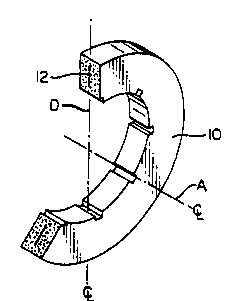
Figure 1 is a section view of a carbon composite
brake disc made in accordance w th the present invention;
Figure 2 is an annular-shaped insert member;
Figure 3 is an annular-shaped insert member
including a plurality of circul~r openings;
ET
- : :
:', -. -' :,
~' . .: ~ ', ,,:
.

wo g2/l4g46 2 1 0 1 6 3 ~ PCT/US92/~o
-- 3 --
Figure 4 is an annular-shaped insert member
including two radially spaced-apart rings of circular
openings;
Figure 5 is an annular-shaped insert member
having a plurality of annularly spaced-apart segmented
openings;
Figure 6 is an annular-shaped insert member
having therein a rinq of diamond-shaped openings;
Figure 7 is an annular-shaped insert member
having therein a plurality of radially spaced-apart rings
of diamond-shaped openings;
Figure 8 i8 a generally annular-shaped insert
member having an irregular-shaped perimeter and with a
plurality of circular openings;
Figure 9 is a generally annular-shaped insert
member having an irregular shaped perimeter and with a
plurality of diamond-~haped openings;
Figure 10 i~ a yartial soction view of a carbon
compo~ite brake disc having therein an in~ert member
located off~et from the diametral center line of the disc;
Figur~ an illu~tration of two worn carbon
compo~it- d$~c~, such as that illu~trated in Figure lO,
after refurbishment via a two-for-one refurbi~hment
method;
Figure 12 is a graph illustrating undesirable
vibration of an aircraft brake having carbon composite
brake discs esperiencing negative damping;
Figure 13 is a graph illustrating the effects of
positive damping in an aircraft brake having carbon com-
posite brake di~cs made in accordance with the present
invention; and
Figure 14 is an illustration of an aircraft brake
utilizing therein the present invention
The object of the present invention is to intro-
duce positive damping into the brake system in order tosubstantially reduce or eliminate squeal vibration without
increasing adverse warpage or reducing the strength of
,
:
- ~.. -
. - . , .

W092/14946 2 1 ~ 1 6 3 ~ 4 _ PCT/~S92/OW80
brake components. The brake system may comprise an air-
craft brake, a clutch, or any friction mechanism utilized
to control the movement of one member of the mechanism
relative to another member. This is accomplished by the
integration into the disc (or discs) of rings or segments,
in continuous, intermittent, shredded or other geometric
piece forms of a temperature resistant or temperature
resistant forming material which in the final disc form
is believed by some to result in positi~e or hysteretic
damping by the presence of the rings or segments and the
interface created, when the disc is being stressed.
~ysteretic damping can be defined as damping wherein
internal work within the material results in the dissipa-
tion of energy. Disc stresses and deflections are multi-
dimensional in natùre due to the superposition of in-plane
torsional, out-of-plane bending and asial deflections
which occur due to localized actuation and asial reaction
forces impo~ed during braking. The integral damping
in~-rt m~mber~ of the pre~ent invention ha~e been
~elected in order to take ad~antag- of positive damponing
mechani~m~ which reduce ~queal vibrations in the brake
~ystem. Weak bonding between the damping ~nsert member
and tho surrounding carbon fiber composite will promote
positive damping under dynamic loading conditions. This
can be accompli~hed by the use of a graphite material
such as GrafoilG9 that forms a poor surface bond due to
the low cohesive strength of its graphite particulate
structure. The damping in~erts may be of single or
multiple layer~. Figure 1 illustrate~ a section view of
a carbon compo~ite brake disc including a damping insert
member in accordance with the pre~ent in~ention. Disc 10
is made of a carbon composite material, as described in
further detail below, and includes therein a damping
ins-rt member 12 in the form of an annulus which provides
a discontinuity within the carbon composite material.
Although the discontinuity comprises the material of the
damping insert member rather than a void, the effect of
the insert member is to effect positive vibration damping
, . .. :. ~, - ~

W O 92/14946 2 1 ~ 1 6 3 t~ P~r/US92/00480
of disc lO during dynamic loading conditions such as the
operation of a brake in which the disc is located.
Multiple layers of the damping insert member 12 would
provide additional surfaces for interacting and dampening
squeal vibrations. The internal damping insert member 12
may be thin (for e2ample, a single layer of 0.005 inch)
such that interfacial damping is dominant, or thicker
(for esample, 0.02 inch) to increase hysteretic damping
contribution. If a strong interfacial bond is achieved
between the carbon composite and damping insert member,
hysteretic damping would be a mechanism of vibration
reduction.
US-A-4,585,096 discloses the use of a thin sepa-
rator disc between split discs in order to suppress noise
and vibration and enhance dissipation of heat. Because
split disc members are utilized, there tends to be a gross
motion between the disc members during operation of the
associatea brake such that the separator disc member may
bo worn away and thon migrate or movo away from between
the split ~isc8. Such a structuro promotes tho destruc-
tion of the soparstor disc. Tho utilization of an inter-
nal, damping insert member in accordance with the present
invention eliminates such wearing away and destruction
because, first, there does not e~ist any motion between
two split discs since only a single integral disc is uti-
lized. Second, the single integral disc with the inter-
nally disposed damping insert member promotes positive
damping on a significantly different scale than e~ists
when two split aiscs disposed about a separator disc is
utilized. Third, the damping insert member is located
entirely within the integral disc member so that it cannot
migrate or move out of the disc member. EP-A-0 020 389
discloses the utiliz ion of two split disc members in
order to reduce noise and inhibit vibration. Interposed
between the disc members is a separating sheet member of
graphite foil or other similar material to prevent melting
or welding together of the two disc members under the
high temperatures and pressures of operation. Because of

W092/14946 2 ~ O 1 6 3 ~ 6 - PCT/U5921~U
the movement of the two disc members relative one another
during operation of the brake, the wear effects upon the
separating sheet member could be even more devastating.
Because the discs have an opening at the outer and inner
diameters thereof, the separating sheet member is permit-
ted to move or migrate outwardly away from the opposing
interfaces of the disc members and lose its effectiveness.
The damping insert members disclosed in accordance with
the present invention are located entirel~ within the
integral disc member so that they cannot migrate or move
outwardly of the dis- member.
Embodiments of damping insert members utilizable
within the present invention are illustrated in Figures
2-9. Figure 2 illustrates the annular-shaped damping
insert member 12 shown in Figure l. Member 12 comprises
a continuous annular-shaped member which will efect dis-
continuities within the a~sociated carbon composite brake
di~c. Figure 3 iilu~trates an annular-~haped damping
in~rt m~mb-r 14 including a plurality of openings 16 in
the form of circle~. It i~ believ-d that the u~e of such
opening~ in the dam~ing in~ert membsr will provide
improved disc integrity by effecting better continuity of
the carbon compo~its material across or through the
openings, and may affect positive damping. Figure 4
illustrates an annular-shaped damping insert member 18
including therein two rings of radially spaced-apart
circular openings 20 and 22 which are circumferentially
off~ot relativo to one another. Figure 5 illustrates an
annular-~haped damping insert member 24 having a plurality
of angularly spaced-apart arcuate~haped segments 26.
Figure 6 illustrates an annular-shaped damping insert
member 28 having therein a ring of openings 30 which are
diamond-shaped. Figure ? illustrates an annular-shaped
damping in~ert member 32 having therein a plurality of
radially spaced apart rings of diamond-shaped openings
34. Figure 8 illustrates a generally annular-shaped
damping insert member 36 having irregular or varying
radial dimension portions 38, 39 wherein portions 38

wos2/14946 210163 ~ PCT/US92/~o
_ 7 _
include circular openings 40. Figure 9 illustrates a
generally annular-shaped damping insert member 42 with an
irregular shaped perimeter and having therein a ring of
diamond-shaped openings 44. The use of damping insert
members which include openings, regular or irregular,
segmented openings, or shredded damping insert members
should increase the cross coupling strength of the carbon
composite material within the disc and thus enhance the
utilization of worn discs for reuse after overhaul. It
is not essential that the damping insert member be planar
when introduced during the manufacturing of a disc or
when manufacturing is completed. Annular-shaped damping
insert members are preferrable due to ease of handling.
The utilization of damping insert members in
accordance with the present invention provides a number
of significant advantages over prior vibration damping
methods such as split discs, split discs sandwiched about
a separator disc member, and split discs with a separating
sheet member. The positive damping insert member of the
present invention i8 an integral part of the brake disc.
Thu~, the resulting disc is not split or layered. Full
structural capability of each disc is maintained. Because
the invention provides internal damping effected by
including the damping insert member~s) within the carbon
composite during processing, the damping insert member(s)
become an integral internal component of a one-piece
carbon composite disc. The localized interfacial strength
between a damping insert member (or damping insert mem-
bers) and carbon composite material can be controlled in
order to achieve the desired degree of positive damping.
Likewise, hysteretic damping can be controlled by vari-
ation in damping insert member volume, composition and
microstructure. The integral nature-of the carbon com-
posite disc prevents half-disc warpage that can occur in
split discs utilized previously. Finally, the integral
nature of the disc will permit a two-for-one brake disc
..
.
; . . ~ .
,
' ,. ' :

wos2/l4s46 PCT/US92/00480
2101636 - 8 -
refurbishment without reprocessing. Such cannot be easily
accomplished if the disc were initially split as previ-
ously described. Referring to Figure lO, there is illus-
trated in partial section view a carbon composite brake
disc 50 which includes a damping insert member 52 that is
offset from the diametral center line of disc 50. It
should be clearly understood that damping insert member
52 can be located along the diametral center line (as
illustrated by center line D in Figure l) or it can be
offset any distance from the diametral center line of the
disc. It is important that damping insert ~ember 52 be
located a sufficient distance from an asial friction face
54, 56 of disc 50 so that during wear or usage the
friction surface will not wear down to the point that the
damping insert member is at the friction surface and
would be worn away or disintegrated. A two-for-one disc
refurbishment method would utilize disc 50 with insert
membor 52 such that one friction face 56 of disc 50 would
be d-signated as a future friction face in the two-for-one
refurbishment proce~s. Aft-r disc 50 has been worn, two
such worn discs 50 are coupled together to form a refur-
bished disc member 60 wherein each friction face 56 is
disposed asially outwardly for engagement with an ad~acent
disc and the damping insert members 52 are located asially
inwardly ad~acent faces 54. Thus, refurbished brake disc
60 provides at each friction face 56 the masimum amount
of asial depth of composite material for wear during use
in an associated brake.
A carbon composite brake disc utilizing a damp-
ing insert member in accordance with the present invention
may be manufactured by se~eral methods. Described below
are three esemplary methods for manufacturing such a
brake disc. A first manufacturing method comprises the
use of molded random carbon fiber to provide a composite
brake disc. A carbon composite brake disc has been
prepared by incorporating a damping insert member into a
preform which was subsequently compression molded and
. .
, ~ , :
- , . . .
. , .. - ~
.~ . ... . . .

WO92/14946 2 l O 1 6 3 1~ PCT/US92/~80
processed into a one-piece brake disc. A number of such
brake discs comprisin~ stator and rotor friction compo-
nents were manufactured. The following is a summary of
the process steps of the manufacturing method. First, a
quantity of chopped carbon fiber~phenolic molding compound
required to fabricate a brake disc preform is divided
into two portions. The two portions may be either equal
or unequal, depending on whére it is desired for the
damping insert member to be disposed asially within the
preform and resulting disc. One portion of the molding
compound is uniformly added to a preform die. Then the
damping insert member, in this case a graphite annulus of
Grafoil ~D , was placed in the preform die on the surface
of the molding compound. The annular damping insert
member can vary in its inner diameter, outer diameter,
thickness and number of layers. However, it must have a
smaller outer diameter than the preform and a larger
~nner diameter than the preform. Additionally, it should
b- gener-lly centered with re~yect to the asial center
line of th- preform (see asial center line A of Figure
1). Altornatively, an annular in~ert may b- effected by
add~ng damping insert material in the form of shredded
foil or other geometric piece forms such as circles,
rectangles, triangles, etc. Then the second portion of
the molding compound is a~ded to the preform die. Nest,
the preform is formed by application of heat and by com-
pression of the preform in the asial direction. The
resulting preform is then used to form a molded carbon/
phenolic disc by a compression molding process ~heat and
pressure). The resulting molded disc contains the damping
insert member as an integril part of its structure. Ne~t,
the molded disc is processed into a carbon-carbon aircraft
brake disc by a series o. process steps including carbon-
ization to convert the phenolic to carbon, densification
by chemical vapor deposition (CVD) into a porous struc-
ture, and heat treatment (1600-2800-C) to produce a carbon
or graphite of the desired crystal structure. The carbon
.
:. .
..
:
~ ' ' . ~ - -'

WO92/14946 2~ ~163~ PCT/US92/~0
-- 10 --
material is then machined to final dimensions. Numerous
variations of the basic carbonization and densification
steps may be utilized. Alternatively, the CVD process
can be replaced by multiple cycles of char-forming liquid
impregnation~carbonization to fill the pores of the com-
posite with carbon. If a thermosetting resin (phenolic)
or other compound is utilized, the carbonized disc is
impregnated followed by curing and charring, and then the
steps of impregnation, curing and charring are repeated
until the desired disc is provided. If pitch in the form
of coal tar or petrGleum is utilized, then the pitch is
melted and impregnated into the disc followed by charrinq.
The charring may be effected under pressure. Whichever of
the steps is utilized (CVD, thermosetting resin, pitch),
the resulting carbon-carbon brake disc contains a damping
insert member which is an integral part af the disc
structure.
It i~ propo~ed to utilize the present invention
in molded, laminated fabric compo~ites. In this method
o pro~iding a carbon compo~ite aircraft brake disc, the
di~c i~ pre~ared by incorporating ~amping insert member~s)
into molded, laminated woven or nonwov-n fabric construc-
tions ~layer-on-layer of carbon cloth~phenolic prepreg)
in a manner ~imilar to the above esample. The impregnated
fabric material is heated to a low temperature of less
than 200-C to remove volatiles. In~tead of utilizing
molding compouna, the carbon cloth~phenolic prepreg of
fabric material in the form of annular rings or ring
segments is usea to prepare the preform. When a first
portion or half of the prepreg cloth or fabric is added
to the preform die, the damping insert member i5 added,
followed by the remainder of the prepreg. The preform is
then formed, followed by disc molding and carbon-carbon
processing as above. Carbonization is typically at
800-llOO-C, and final heat treat is at 1600-2800-C,
followed by machining. The resulting brake disc will
contain the damping insert as an integral part of the
disc structure.
, . - , , .

WO92/14946 2 1 0 1 fi 3 6 PCT/US92/~0
A third proposed method of providing a brake
disc with the damping insert member of the present inven-
tion comprises the utilization of nonwoven laminated
fabric composites. Nonwoven laminated fabric preforms
are prepared ~rom multi-layers of random and/or oriented
mats which are reinforced in the through-thickness direc-
tion by testile processes such as needling, sewing or
tufting. -The resulting preforms have multi-directional
reinforcement and are used as the precursor for subse-
quent processins into carbon-cirbon composites. In the
preparation o such preforms for use in manufacturing
carbon composite brake discs, it is possible to produce
preforms in the general shape of the brake discs being
manufactured. During the ~build-up~ of the preform, it
is possible to incorporate a damping insert member(s)
into the center of the preform by substituting a material
such as Grafoil for annular ring(s) or segment(s) of
the preform. As with the previous two e~amples, the
damping insert member must have a smaller outer diameter
and a larger inner diametor than the preform. Tho
neodling or other methods of achieving through-thickness
reinorcement will penetrate the damping insert member
and should provide damping efectiveness. The nonwoven
laminated fabric preform can be subjected to carbon-carbon
procos~ing as discussed above. The interconnected layers
or mats and damping insert member may receive a final
heat treat of 1600-2800-C followed by machining. ~he
resulting carbon-carbon brake disc will contain the
damping insert as an integral part of the disc structure.
Carbon composite brake discs were prepared in
accordance with the first esample and were processed into
finished carbon discs that were subjected to both dynamic
structural tests and vibration characterization tests.
These brake discs each had an annular shaped damping
insert member of Grafoil ~ as illustrated in Figure 2.
The results of the dynamic structural tests demonstrated
that composite discs with damping insert members are able
:, . .. . .

WO92/14946 ' PCT/US92/00480
to maintain structural integrity to the same degree as
composite discs without damping insert members. Figure
12 is a graphic illustration of undesirable vibration
comprising brake "squeal~ present in a prior aircraft
brake having carbon composite brake discs not made in
accordance with the present invention. The aircraft
brake was run throuqh multiple cold tasi (40mph - 0),
landing, and hot ta~i (40mph - Smph~ stops. Figure 12
illustrates the vibration e~perienced by the brake system
(in terms of acceleration in G (gravitational) force)
during the multiple series of cold tasi, landing, and hot
tasi stops. The vibration or squeal of the aircraft brake
was significant. Figure 13 is a graphic illustration of
an aircraft brake having carbon composite brake discs
includinq damping insert members in accordance with the
first esample above. The graph illustrates vibration
characterization tests conducted on a full scale brake in
a laboratory. A similar regimen of multiple cold tasi
~40mph - 0), landing, and hot tasi (40mph - 5mph) stops
was conducted on the brakes to determine the presence and
magnitude of brake squeal type vibrations within the
brake system. The qraph illustrates that all vibrations
over the frequency range tested are essentially eliminated
as compared to the baæeline brake characteristics illus-
trated in Figure 12. In the test covered by this charac-
terization, vibration was essentually eliminated when all
stators and rotors in the brake containing the damping
inserts. The same results were obtained when only the
stators contained the damping inserts. It may be possible
to further reduce the number of discs containing damping
inserts so that only a minimal number of disc~s) with
insert(s) is required to eliminate vibrations comprising
brake sgueal within the brake.
Discs utilizing a damping insert member in
accordance with the present invention may be utilized
3 within many diferent types of friction mechanisms. For
esample, the discs disclosed above comprise carbon-carbon

WO92/14946 21016 3 G PCT/US92/0048~
- 13 -
composite brake discs utilized in aircrat brakes. Such
discs also could be utilized in clutches or any number of
friction mechanisms wherein the movement of one member is
controlled by engagement with an adjacent member or
members. Figure 14 illustrates a typical aircraft brake
100 disposed within a wheel 101 wherein a plurality of
carbon composite rotors 110 are disposed adjacent carbon
composite brake stators 120. Rotors 110 include damping
insert members 115 and stators 120 include damping insert
members 125. The damping insert members may, as disclosed
above, be located on or offset from the diametral center
line of each respective disc, and located relative to the
damping insert member of an adjacent disc in numerous
configurations such as those illustrated in Fi~ure 14.
~ 7 .;

Dessin représentatif
Une figure unique qui représente un dessin illustrant l'invention.
États administratifs

2024-08-01 : Dans le cadre de la transition vers les Brevets de nouvelle génération (BNG), la base de données sur les brevets canadiens (BDBC) contient désormais un Historique d'événement plus détaillé, qui reproduit le Journal des événements de notre nouvelle solution interne.

Veuillez noter que les événements débutant par « Inactive : » se réfèrent à des événements qui ne sont plus utilisés dans notre nouvelle solution interne.

Pour une meilleure compréhension de l'état de la demande ou brevet qui figure sur cette page, la rubrique Mise en garde , et les descriptions de Brevet , Historique d'événement , Taxes périodiques et Historique des paiements devraient être consultées.

Historique d'événement

Description Date
Inactive : CIB de MCD 2006-03-11
Le délai pour l'annulation est expiré 2000-01-21
Demande non rétablie avant l'échéance 2000-01-21
Réputée abandonnée - omission de répondre à un avis sur les taxes pour le maintien en état 1999-01-21
Inactive : Abandon.-RE+surtaxe impayées-Corr envoyée 1999-01-21
Demande publiée (accessible au public) 1992-08-15

Historique d'abandonnement

Date d'abandonnement Raison Date de rétablissement
1999-01-21

Taxes périodiques

Le dernier paiement a été reçu le 1997-12-31

Avis : Si le paiement en totalité n'a pas été reçu au plus tard à la date indiquée, une taxe supplémentaire peut être imposée, soit une des taxes suivantes :

  • taxe de rétablissement ;
  • taxe pour paiement en souffrance ; ou
  • taxe additionnelle pour le renversement d'une péremption réputée.

Les taxes sur les brevets sont ajustées au 1er janvier de chaque année. Les montants ci-dessus sont les montants actuels s'ils sont reçus au plus tard le 31 décembre de l'année en cours.
Veuillez vous référer à la page web des taxes sur les brevets de l'OPIC pour voir tous les montants actuels des taxes.

Historique des taxes

Type de taxes Anniversaire Échéance Date payée
TM (demande, 6e anniv.) - générale 06 1998-01-21 1997-12-31
Titulaires au dossier

Les titulaires actuels et antérieures au dossier sont affichés en ordre alphabétique.

Titulaires actuels au dossier
ALLIED-SIGNAL INC.
Titulaires antérieures au dossier
MCALLISTER LAWRENCE EDWARD
DAVID ROSS SNYDER
JARING VANDER VEEN
Les propriétaires antérieurs qui ne figurent pas dans la liste des « Propriétaires au dossier » apparaîtront dans d'autres documents au dossier.
Documents

Pour visionner les fichiers sélectionnés, entrer le code reCAPTCHA :


Pour visualiser une image, cliquer sur un lien dans la colonne description du document. Pour télécharger l'image (les images), cliquer l'une ou plusieurs cases à cocher dans la première colonne et ensuite cliquer sur le bouton "Télécharger sélection en format PDF (archive Zip)" ou le bouton "Télécharger sélection (en un fichier PDF fusionné)".

Liste des documents de brevet publiés et non publiés sur la BDBC .

Si vous avez des difficultés à accéder au contenu, veuillez communiquer avec le Centre de services à la clientèle au 1-866-997-1936, ou envoyer un courriel au Centre de service à la clientèle de l'OPIC.


Description du
Document 
Date
(aaaa-mm-jj) 
Nombre de pages   Taille de l'image (Ko) 
Abrégé 1992-08-14 1 45
Revendications 1992-08-14 3 115
Dessins 1992-08-14 3 84
Abrégé 1992-08-14 1 59
Description 1992-08-14 13 563
Dessin représentatif 1998-11-16 1 6
Rappel - requête d'examen 1998-09-21 1 116
Courtoisie - Lettre d'abandon (taxe de maintien en état) 1999-02-17 1 184
Courtoisie - Lettre d'abandon (requête d'examen) 1999-03-03 1 172
Taxes 1996-12-29 1 72
Taxes 1995-12-27 1 71
Taxes 1994-12-21 1 80
Taxes 1993-07-28 1 53
Rapport d'examen préliminaire international 1993-07-28 15 306