Sélection de la langue

Search

Sommaire du brevet 2101657 

Énoncé de désistement de responsabilité concernant l'information provenant de tiers

Une partie des informations de ce site Web a été fournie par des sources externes. Le gouvernement du Canada n'assume aucune responsabilité concernant la précision, l'actualité ou la fiabilité des informations fournies par les sources externes. Les utilisateurs qui désirent employer cette information devraient consulter directement la source des informations. Le contenu fourni par les sources externes n'est pas assujetti aux exigences sur les langues officielles, la protection des renseignements personnels et l'accessibilité.

Disponibilité de l'Abrégé et des Revendications

L'apparition de différences dans le texte et l'image des Revendications et de l'Abrégé dépend du moment auquel le document est publié. Les textes des Revendications et de l'Abrégé sont affichés :

  • lorsque la demande peut être examinée par le public;
  • lorsque le brevet est émis (délivrance).
(12) Demande de brevet: (11) CA 2101657
(54) Titre français: MACHINE POUR L'IMPRESSION OFFSET D'OBJETS PLATS, NOTAMMENT DES DISQUES COMPACTS
(54) Titre anglais: MACHINE FOR THE OFFSET PRINTING OF FLAT OBJECTS, IN PARTICULAR FOR COMPACT DISCS
Statut: Réputée abandonnée et au-delà du délai pour le rétablissement - en attente de la réponse à l’avis de communication rejetée
Données bibliographiques
(51) Classification internationale des brevets (CIB):
  • B41F 17/00 (2006.01)
  • B41F 17/26 (2006.01)
  • G11B 7/26 (2006.01)
  • G11B 23/40 (2006.01)
(72) Inventeurs :
  • TERZI, FERMO (Italie)
  • VERONA, MASSIMO (Italie)
(73) Titulaires :
  • O.M.S.O. S.P.A.
(71) Demandeurs :
  • O.M.S.O. S.P.A. (Italie)
(74) Agent: ROBIC AGENCE PI S.E.C./ROBIC IP AGENCY LP
(74) Co-agent:
(45) Délivré:
(22) Date de dépôt: 1993-07-30
(41) Mise à la disponibilité du public: 1994-02-01
Requête d'examen: 2000-06-19
Licence disponible: S.O.
Cédé au domaine public: S.O.
(25) Langue des documents déposés: Anglais

Traité de coopération en matière de brevets (PCT): Non

(30) Données de priorité de la demande:
Numéro de la demande Pays / territoire Date
RE 92A000063 (Italie) 1992-07-31

Abrégés

Abrégé anglais


- 9 -
ABSTRACT
MACHINE FOR THE OFFSET PRINTING OF FLAT OBJECTS, IN PARTICULAR FOR
COMPACT DISCS
A printing machine of offset type for compact discs comprises at
least one printing cylinder for at least one colour driven with
uniform rotary motion and a chain conveyor driven with
intermittent motion for feeding the objects to be printed.

Revendications

Note : Les revendications sont présentées dans la langue officielle dans laquelle elles ont été soumises.


- 7 -
PATENT CLAIMS
1. A printing machine of offset type for flat objects, in
particular for compact discs, of the type comprising a flat
conveyor for feeding the objects to be printed to at least one
printing cylinder for at least one colour, said cylinder being
driven with uniform rotary movement, characterised by comprising:
- an endless chain conveyor having a rectilinear upper portion;
- means positioned at regular intervals along said conveyor to
receive the object to be printed and maintain it in position;
- means for driving said conveyor with intermittent movement in
which halt periods alternate with periods during which the speed
increases, then remains constant and then decreases;
- at least one printing station comprising a printing cylinder
of offset type;
- means for loading and discharging the objects onto and from
the conveyor, and operated in synchronism with its halt periods.
2. A machine as claimed in claim 1, characterised in that at
least the rectilinear upper portion of the chain conveyor is
guided within suitable slide tracks which receive idle lateral
wheels mounted on the hinging axes of the chain links, and idle
central wheels mounted on the chain links with their axis
perpendicular to the hinging axes of the chain links.
3. A machine as claimed in claim 1, characterised in that a
slab, which at those portions thereof concerned with the
operation is laterally supported by idle aligned wheels, is fixed
to those chain links which are intended to support the objects to
be printed.
4. A machine as claimed in claim 1, characterised in that the
means which drive the conveyor with intermittent movement comprise
a movement regulator in which two antisymmetrical parallel cams
driven with uniform movement each interfere with one of two
identical circumferential series of rollers supported by a shaft
connected to the shaft of the toothed wheel driving the chain.

- 8 -
5. A machine as claimed in claim 1, characterised in that the
conveyor links are plates which at their mutual hinging points are
guided to undergo a circumferential trajectory tangential to a
rectilinear trajectory.

Description

Note : Les descriptions sont présentées dans la langue officielle dans laquelle elles ont été soumises.

MACHINE FOR THE OFFSET PRII~TING OF FLAT t~l3JECTS, IN PARTICIJLAR FOR
COMPACT DISCS ;
The purpose of the present invention is to confront the problem of
5 the offset printing of flat objects, such as compact discs. ;~
~ .
The ever increasing distribution of this type of object has made
it essential in practice to subject them directly to the multi-
colour printing of the brand name and other information required
to identify their contents.
.
Such articles are currently offset printed on machines comprising
an object conveyor which advances at constant speed below at least
one printing station, the printing cylinder of which carries a
series of equidistant cylindrical segment-shaped printing plates
which have collected the image inked in the various ir~ing
stations positioned peripherally to the printing cylinder, and
deposit it on the objects as they pass below them,
The circumferential distance apart of said printing plates equals
the linear distance between the objects to be printed which
advance on the underlying conveyor, the peripheral speed of the
printing plates being exactly equal to the rectilinear speed of
the underiying conveyor.
With this type of machine, which has proved suitable for printing
large flat objects, problems arise when used for printing ~
particularly delicate objects. `~;
.
', ' . ~'':

2 ~
- 2 -
In this respect, it is virtually impossible to accurately position
delicate object such as a compact disc on a moving conveyor
feeding it below a printin~ station with~ut sub~;ecting the object
to impacts ~nd jolting which could damage it.
Again, an offset printing ~achine could not be operated ~
intermittently because the cyclic stoppage of the printing -~ -
cylinder would compromise the proper operation of the inking ` ; -
rollers.
'
The object of the present invention is to obviate the aforesaid
drawback by providing an offset printing machine for delicate flat
objects, in which the conveyor feeding the objects below the
printing cylinder advances with intermittent movement comprising
lS halt periods separated by movement periods during which the
conveyor undergoes acceleration. then a period of uniform movement
and then deceleration, its linear speed during the period of
uniform movement being equal to the peripheral speed of tbe
printing plates located on the printing cylinder, which instead
rotates with uniform movement.
The halt periods are sufficiently long to enable the objects to be
loaded onto and discharged from the conveyor.
The printing plates carried peripherally by the printing cylinder
are spaced apalt by a distance depending on the halt and movement
periods of the underlying conveyor,~so that the printing cylinder
can continue to rotate with uniform movement to hence allow
correct inkinK of the printing plates, even when the underlying
con~eyor cyclically stops.
;
The merits and operational and construction~l characteristics of
the invention will be more apparent from the detailed description
given hereinafter with reference to the figures of the
accompanyin~ draw;ngs, which illustrdte a preferred embodiment of
the invention by way of non-limiting example.

2 ~ 7
3 --
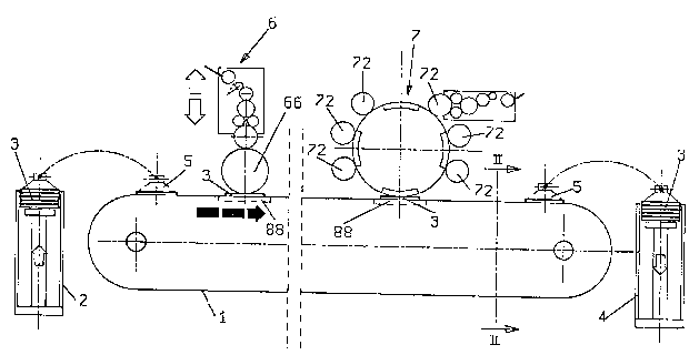
Figure 1 is a schematic side view of the inventioll;
Figure 2 is a section on the line II II of Figure l;
Figure 3 is A schemdtic plan view of the invention;
Figure 4 is a front view of the device which transmits
intermittent movement to the conveyor;
Figure 5 is a view in the direction V of Figure 4;
Figure 6 is a diagram showing the conveyor speeds during one
working cycle, as imposed by the devices shown in Figure 4 and
Figure 5; ~:
Figure 7 is a plan view of one of the constituent plates of the
object feed conveyor;
Figure 8 is a section on the line VIII-VIII of Figure 7.
The figures show a conveyor 1 positioned between a device 2 for
15 loading the objects 3 to be printed and a device 4 for collecting ..
the printed objects 3. .:
Sucker means 5 are provided between the devices 2 and 4 and the
conveyor 1 to withdraw the objects from the device 2 and place
20 them on the conveyor 1, and to withdraw the objects from the ` .
conveyor 1 and place them in the device 4 after printing.
In the illustrated embodiment two printing units 6 and 7
respectively are positioned above the upper portion of the
conveyor 1.
.
The device 6 is a single-colour device comprising a printing
cylinder 66 which is brought into contact ~ith the underlying
object 3 moving along the conveyor 1. .
In the illustrflted embodiment the printing device 7 is ~ six-
colour device in which the inking stations have been omitted for
clarity of drawing, only one of them being indicated
schematically.
Four equidistant printing plates 71 of suitable material are ~ :
positioned on the printing cylinder 77 to receive the image inked ~ ;
~',''
.. . ` ~ ' '

in its various colours by the six inking rollers and transfer it
onto the object 3, which is carried below the cylinder 77 by the -~
conveyor 1.
The conveyor :I consists of a strong central tubular frame 8
(Figure 2) carrying slide guides 9 on its upper side and lower
side.
Iwo mutually facing slide guides 9 are provided on each of the
10 upper and lower sides and are each composed of three parts 91, 92 ~:
and 93, so that overall they create slide tracks for wheels of
vertical axis and horizontal axis as described hereinafter.
The conveyor 1 slides on the ~rame 8 after passing about two end
toothed wheels, not shown, and is composed of a series of links in
the form of plates 10, better seen in Figures 7 and B, which
ext~rnally carry wheels 12 on their mutual hinging axes 11, and
lowerly carry a centering wheel 13 with its axis perpendicular to
the hinging axis 11.
l~e wheels 12 and 13 slide in the tracks created by the guides 9
as stated, and as can be seen in Figure 2.
On the opposite side to that comprising the wheel 13 each
constituent plate 10 of the chain supports a slab 14 of treated
steel, projecting laterally from the guides 9.
;
A seat 15 for receiving one of the objects to be printed is fixed
at regular intervals on each slab 14. The seats 15 centr~lly
comprise a projecting pin 16 to be inserted into the central hole
in a co~pact ~isc 3, which is thus maintained in a fixed position
during the printing operations.
During the operation of the machine the pin 16 is received in a
c~vity, not shown, provided in the cylinder 66 and in the printing
plates 71.
'

~la~7
- 5 -
Two series of aliKned support rollers 89 are fixed by brackets 8
to the sides of the central frame 8 on those portions below the
printing stations 6 and 7 to act as a sliding support for the
slabs 14, hence providing rigidity to the systeln during printing.
With particular reference to Figure 3 it can be seen that the
machine comprises a single motor 19 which via a first step-down
gear 20 operates a programmer ~echanism 21 responsible for the
intermittent movement of the conveyor 1. ~
~ '
The programmer mechanism ?1 is shown in Figures 4 and 5, and
consists of a bush 22 carrying two facing parallel flat cams 23
and 24 of antisymmetrical development.
The bush is keyed onto the output shaft 25 of the step-down gear
20 and is rotatably supported by an external structure, not shown,
which supports a second bush 26 which receives and is coupled to
the exit shaft 27 of the device.
The bush 26 connects together three parallel plates 28, 29 and 30,
between which there are positioned two groups each of three
equidistant idle rollers 31.
The two groups of three rollers positioned between the plates 28
and 29 and between the plates 29 and 30 are arranged to interact
with the described cams 23 and 24 respectively, and are displaced
by sixty degrees from each other.
The exit shaft 27 is connected to one of the toothed wheels about
which the conveyor 1 passes and is driven.
,
Because of the aforedescribed configuration, as can be seen from
Figure 6 the exit shaft 27 and hence the conveyor 1 are driven ~ ;
with intermittent movement comprising a first stage corresponding
to 270 degrees of rotation of the output shaft 25 of the step-down
gear 20 during which the speed of the shaft 27 increases, then
remains constant and finally decreases to zero, and a second stage ~ `

2 ~ 7
- 6 -
corresponding to one quarter of a revolution of the shaft 25
during which the speed of the shaft 27 remains at zero.
~y virtue of the described device the conveyor 1 which receives
5 the objects to be printed and feeds them below the printing `
cylinders is driven with an intermittent movement comprising halt
stages during which the object to be printed can be easily loaded -~
onto the seat 15 provided on the conveyor 1, and printing stages
during which the conveyor moves at a constant speed exactly equal
to the peripheral speed of the printing plates 71 pro~ided on the
print;ng cylinder 77 and at the peripheral speed of the cylinder
66.
The printing cylinders 66 and 77 are rotated by independent
mechanical transmissions connected to the motor 18 at a constant
speed such that the respective peripheral speeds are exactly equal
-to the linear speed of advancement of the conveyor 1 during the
periods in which it moves at constant speed.
In the illustrated embodiment, relating to the printing of compact
discs, the conveyor 1 is composed of 72 plates 10, has a distance
between the axes of the toothed wheels of 3600 mm, and supports 36
seats 15 for receiving compact discs 3.
If the peripheral speed of the printing means is 40 m/min, 100
objects can be printed per minute.

Dessin représentatif
Une figure unique qui représente un dessin illustrant l'invention.
États administratifs

2024-08-01 : Dans le cadre de la transition vers les Brevets de nouvelle génération (BNG), la base de données sur les brevets canadiens (BDBC) contient désormais un Historique d'événement plus détaillé, qui reproduit le Journal des événements de notre nouvelle solution interne.

Veuillez noter que les événements débutant par « Inactive : » se réfèrent à des événements qui ne sont plus utilisés dans notre nouvelle solution interne.

Pour une meilleure compréhension de l'état de la demande ou brevet qui figure sur cette page, la rubrique Mise en garde , et les descriptions de Brevet , Historique d'événement , Taxes périodiques et Historique des paiements devraient être consultées.

Historique d'événement

Description Date
Inactive : CIB de MCD 2006-03-11
Demande non rétablie avant l'échéance 2005-06-09
Inactive : Morte - Aucune rép. dem. par.30(2) Règles 2005-06-09
Réputée abandonnée - omission de répondre à un avis sur les taxes pour le maintien en état 2004-07-30
Inactive : Abandon. - Aucune rép dem par.30(2) Règles 2004-06-09
Inactive : Dem. de l'examinateur par.30(2) Règles 2003-12-09
Lettre envoyée 2000-07-12
Inactive : Renseign. sur l'état - Complets dès date d'ent. journ. 2000-07-12
Inactive : Dem. traitée sur TS dès date d'ent. journal 2000-07-12
Toutes les exigences pour l'examen - jugée conforme 2000-06-19
Exigences pour une requête d'examen - jugée conforme 2000-06-19
Demande publiée (accessible au public) 1994-02-01

Historique d'abandonnement

Date d'abandonnement Raison Date de rétablissement
2004-07-30

Taxes périodiques

Le dernier paiement a été reçu le 2003-06-10

Avis : Si le paiement en totalité n'a pas été reçu au plus tard à la date indiquée, une taxe supplémentaire peut être imposée, soit une des taxes suivantes :

  • taxe de rétablissement ;
  • taxe pour paiement en souffrance ; ou
  • taxe additionnelle pour le renversement d'une péremption réputée.

Les taxes sur les brevets sont ajustées au 1er janvier de chaque année. Les montants ci-dessus sont les montants actuels s'ils sont reçus au plus tard le 31 décembre de l'année en cours.
Veuillez vous référer à la page web des taxes sur les brevets de l'OPIC pour voir tous les montants actuels des taxes.

Historique des taxes

Type de taxes Anniversaire Échéance Date payée
TM (demande, 5e anniv.) - générale 05 1998-07-30 1998-07-07
TM (demande, 6e anniv.) - générale 06 1999-07-30 1999-07-07
Requête d'examen - générale 2000-06-19
TM (demande, 7e anniv.) - générale 07 2000-07-31 2000-07-19
TM (demande, 8e anniv.) - générale 08 2001-07-30 2001-07-09
TM (demande, 9e anniv.) - générale 09 2002-07-30 2002-07-12
TM (demande, 10e anniv.) - générale 10 2003-07-30 2003-06-10
Titulaires au dossier

Les titulaires actuels et antérieures au dossier sont affichés en ordre alphabétique.

Titulaires actuels au dossier
O.M.S.O. S.P.A.
Titulaires antérieures au dossier
FERMO TERZI
MASSIMO VERONA
Les propriétaires antérieurs qui ne figurent pas dans la liste des « Propriétaires au dossier » apparaîtront dans d'autres documents au dossier.
Documents

Pour visionner les fichiers sélectionnés, entrer le code reCAPTCHA :


Pour visualiser une image, cliquer sur un lien dans la colonne description du document. Pour télécharger l'image (les images), cliquer l'une ou plusieurs cases à cocher dans la première colonne et ensuite cliquer sur le bouton "Télécharger sélection en format PDF (archive Zip)" ou le bouton "Télécharger sélection (en un fichier PDF fusionné)".

Liste des documents de brevet publiés et non publiés sur la BDBC .

Si vous avez des difficultés à accéder au contenu, veuillez communiquer avec le Centre de services à la clientèle au 1-866-997-1936, ou envoyer un courriel au Centre de service à la clientèle de l'OPIC.


Description du
Document 
Date
(aaaa-mm-jj) 
Nombre de pages   Taille de l'image (Ko) 
Dessin représentatif 1998-08-13 1 18
Abrégé 1994-04-29 1 25
Revendications 1994-04-29 2 78
Dessins 1994-04-29 5 201
Description 1994-04-29 6 292
Rappel - requête d'examen 2000-04-02 1 117
Accusé de réception de la requête d'examen 2000-07-11 1 177
Courtoisie - Lettre d'abandon (R30(2)) 2004-08-17 1 166
Courtoisie - Lettre d'abandon (taxe de maintien en état) 2004-09-26 1 178
Taxes 2003-06-09 1 28
Taxes 1998-07-06 1 36
Taxes 2001-07-08 1 31
Taxes 2002-07-11 1 30
Taxes 2000-07-18 1 30
Taxes 1999-07-06 1 31
Taxes 1997-05-12 1 43
Taxes 1995-07-24 1 42
Taxes 1996-07-11 1 43