Sélection de la langue

Search

Sommaire du brevet 2101784 

Énoncé de désistement de responsabilité concernant l'information provenant de tiers

Une partie des informations de ce site Web a été fournie par des sources externes. Le gouvernement du Canada n'assume aucune responsabilité concernant la précision, l'actualité ou la fiabilité des informations fournies par les sources externes. Les utilisateurs qui désirent employer cette information devraient consulter directement la source des informations. Le contenu fourni par les sources externes n'est pas assujetti aux exigences sur les langues officielles, la protection des renseignements personnels et l'accessibilité.

Disponibilité de l'Abrégé et des Revendications

L'apparition de différences dans le texte et l'image des Revendications et de l'Abrégé dépend du moment auquel le document est publié. Les textes des Revendications et de l'Abrégé sont affichés :

  • lorsque la demande peut être examinée par le public;
  • lorsque le brevet est émis (délivrance).
(12) Brevet: (11) CA 2101784
(54) Titre français: MECANISME D'INVERSION
(54) Titre anglais: REVERSE SWITCH ASSEMBLY
Statut: Périmé et au-delà du délai pour l’annulation
Données bibliographiques
(51) Classification internationale des brevets (CIB):
  • H01H 21/00 (2006.01)
  • B25F 05/00 (2006.01)
  • H01H 09/06 (2006.01)
  • H01H 21/22 (2006.01)
(72) Inventeurs :
  • MELROSE, DAVID R. (Etats-Unis d'Amérique)
  • DUBUQUE, KENNETH J. (Etats-Unis d'Amérique)
  • MCCALLOPS, JOHN A. (Etats-Unis d'Amérique)
(73) Titulaires :
  • INGERSOLL-RAND COMPANY
(71) Demandeurs :
  • INGERSOLL-RAND COMPANY (Etats-Unis d'Amérique)
(74) Agent: NORTON ROSE FULBRIGHT CANADA LLP/S.E.N.C.R.L., S.R.L.
(74) Co-agent:
(45) Délivré: 2003-11-25
(86) Date de dépôt PCT: 1992-09-09
(87) Mise à la disponibilité du public: 1993-04-01
Requête d'examen: 1999-03-30
Licence disponible: S.O.
Cédé au domaine public: S.O.
(25) Langue des documents déposés: Anglais

Traité de coopération en matière de brevets (PCT): Oui
(86) Numéro de la demande PCT: PCT/US1992/007590
(87) Numéro de publication internationale PCT: US1992007590
(85) Entrée nationale: 1993-07-19

(30) Données de priorité de la demande:
Numéro de la demande Pays / territoire Date
763,047 (Etats-Unis d'Amérique) 1991-09-20

Abrégés

Abrégé anglais


Disclosed is a modular reverse switch assembly having a rotating disc
actuation
member (8) with a plurality of extending tabs (5) which are spaced apart to
project to
opposite sides of the tool thereby permitting ease of operation by either
hand. The
modular design permits a wide degree of selection in assembly location and
practice.

Revendications

Note : Les revendications sont présentées dans la langue officielle dans laquelle elles ont été soumises.


The embodiments of the invention in which an exclusive property or privilege
is claimed are defined as follows:
1. A reverse switch assembly for a hand held power tool of the type comprising
a
housing; a switch plate means mounted for rotation in said housing for
operation of a
switch; a plurality of spaced apart operating means projecting from said
switch plate
and through a plurality of spaced apart apertures in said housing for rotating
said
switch plate to select a forward or reverse position of said switch; means for
mounting
said housing in a position on said power tool whereby said operating means
projecting
from said switch plate are accessible from both sides of said power tool and
operable
by a proximate digit of either tool holding hand; and wherein said switch
plate means
further comprises a semi-circular plate having a lip formed on a portion of
its
periphery in close proximity to the periphery of said housing.
2. A reverse switch assembly for a power tool according to Claim 1, wherein
said
housing further comprises a partially flattened cylinder form having a hollow
center
and at least one removable end for access.
3. A reverse switch assembly for a power tool according to Claim 2, wherein
said
plurality of spaced apart means projecting from said switch plate arc car like
tabs
radially projecting from said switch plate and extending through apertures
provided in
the periphery of said housing.
4. A reverse switch assembly for a power tool according to Claim 1, wherein
said
means for mounting said housing in a position on said tool further comprises a
plurality of ear like projections extending from said housing for registry
with
complimentary recesses in the power tool.
5. A reverse switch assembly for a power tool according to Claim 1, wherein
said
switch is provided with an operating tine which contacts a cam means on said
switch
plate in one position of said switch plate relative to said housing and is out
of registry
with said switch plate in a second position.

6
6. A reverse switch assembly for a power tool according to Claim 1, wherein
said
switch plate means and said housing are positioned in relative rotation by
means of a
detent formed on a cut leaf spring on said housing.
7. A reverse switch assembly for a power tool according to Claim 6, wherein
the
assembly of said switch plate and sand switch are maintained within said
housing by a
closure means.
8. A reverse switch assembly for a power tool according to Claim 7, wherein
said
closure means is provided with bearing means allowing rotation of said switch
plate
means about a concentric center relative to a peripheral surface of said
housing.
9. A reverse switch assembly for operation by a proximate digit of either hand
comprising:
a hollow cylinder-like housing having a peripheral surface formed to be
concentric about an axis of said cylinder-like housing;
a semi-circular disc like switch operating plate mounted for rotation about
said
axis having a lip forward on a portion of its periphery in close proximity to
the
periphery of said cylinder-like housing and having a plurality of operating
projections
projecting from said switch plate;
said peripheral surface being provided with a plurality of apertures through
which said operating projections extend for manual operation of said switch
plate and
rotation about said axis; and
switch means in register with said housing and said switch plate in one
selected position of said switch plate relative to said housing and out of
registry with
said switch plate in a second position.

Description

Note : Les descriptions sont présentées dans la langue officielle dans laquelle elles ont été soumises.

2l~i~g
REVERSE SWITCH ASSEMBLY
BACKGROUND OF THE INVENTION
This invention relates generally to reversing switches for electric motors and
the like and more particularly to a modular reversing switch for brushless
D.C. electric
hand tools.
Present known art for electric hand tool reversing switches include simple
slide
switches which may be mounted anywhere on the tool. The disadvantage of the
known prior art is that even if the switches are located in relatively
convenient
locations, they are nearly impossible to operate with one hand,' particularly
if the
operator is wearing gloves. This makes the reversing operation generally a two
handed
operation and, depending on the selected location of the switch, may be
inconvenient
for either right-handed or left-handed tool operation.
In addition, the switch mountings do not accommodate well to modern methods
of modular assembly and, as such, often require special stake or screw type
mountings
which are inconvenient to assemble and remove for replacement or repair.
The foregoing illustrates limitations known to exist in the present electric
hand
tool art. Thus, it is apparent that it would be advantageous to provide an
alternative
directed to overcoming one or more of the limitations set forth above.
Accordingly, a
suitable alternative is provided including features more fully disclosed
hereinafter.
SUMMARY OF THE 1NVENTI0~1
1n one aspect of the present invention this is accomplished by providing a
reverse switch assembly comprising a housing; a switch plate means mounted for
rotation in the housing for operation of a switch; a plurality of spaced apart
tab means
projecting from the switch plate and through a plurality of spaced apart
apertures in

CA 02101784 2002-11-04
2
the housing for rotating the switch plate to select a forward or reverse
position of the
switch; and means for mounting the housing in a position on the tool whereby
the tab
means for projecting from the switch plate are accessible from both sides of
the power
tool.
In another aspect of the present invention this is accomplished by providing a
reverse switch assembly for a hand held power tool of the type comprising a
housing;
a switch plate means mounted for rotation in said housing for operation of a
switch; a ,
plurality of spaced apart operating means projecting from said switch plate
and
through a plurality of spaced apart apertures in said housing for rotatSng
said switch .
plate to select a forward or reverse position of said switch; moans for
mounting said
housing in a position on said power tool whereby said operating means
projecting
from said switch plate are accessible from both sides of said power tool and
operable
by a proximate digit of either tool holding hand; andwherei~t said switch
plate means l
further cor»prises a semi-circular plate having a lip formed on a portion of
its
periphery in close proxinuty to the periphery of said housing.
In another aspect of tlae present invention this is accomplished by providing
a
reverse switch assembly for operation by a proximate digit of either hand
comprising:
a hollow cylinder-like housing having a peripheral surface formed to be
concentric
about a» axis of said cylinder-like housing; a semi-circular disc like switch
operating
plate zv,ounted for rotation about said axis having a lip forward on a portion
of its l
peziphery in close proximity to the periphery of said cylinder-like housing
and travir~g .
a plurality of operating projectiorAS projecting from said switch plate; said
peripheral
surface being provided with a plurality of apertures through which said
operating
projections extend for manual operation of said switch plate and rotation
about said
axis; and switch means in register with said housing and said switch plate in
one
selected position of said switch plate relative to said housing and out of
registry with
said switch plate in a second position.
The foregoing and other aspects will bec4me apparent from the following
detailed description of the invention when considered i» canjunetion with the
accompanying drawl»g figures.

CA 02101784 2002-11-04
3
BRIEF DESCRfFTION OF TDRAWING FIGURES
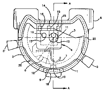
Pig. 1 is ~a partially sectioned front e)evation of a reverse switch assembly
according to the present invezttion; and
Fig. 2 is a cross sectioned side elevation view of the reverse switch assembly
'
l
taken at section A-A of Fig. 1.
l
DETAILED DESCRTPTION
Fig. 1 shows a reverse switch assembly for use with D.C. brushlcss electric
hand tools and the like according to the present invention. As shown in Fig. 1
a l
hollow cylinder-like housing 1 is shown which contains the assembly. The
housing 1
I
is provided with an end plate closure 2 which cooperates with the housing t4
form a
container for the switch assembly. Mounted for rotation within the housing
about a
centerline of the housing is a rotazy switch plate 3 which is in the form of a
l
semicircular half cup having substantially spaced apart extending tabs 5 and
5' which
extend through elongaeed rectangular apertures 20 formed in the periphery of
the
housing.
A. microswitch 4 is mounted to the nonremovablc end 21 of the housing 1 by !
means of two mounting pins 17 which project into switch mourning holes 16
provided
in the microswitch for mounting purposes. The removable end plate or housing
closure 2 is provided with a bearing boss 11 which mounts the rotary switch
plate 3
for rotation about a bearing hole 12 provided in the rotary plate 3. Bearing
bass 11
and a closure spring cooperate to maintain the switch 4 on the mounting pins
I7 and
the rotary plate 3 in close contact with the mierbswiteh ~. !
l
h should be now appreciated by one skilled in the a~-t that assembly of the
switch requires merely that the switch 4 be placed on mounting pin 17 and that
the
rotary plate 3 be assembled on the bearing boss 11 prior to placing the
housing closure
2 on the housing 1. With this assembly the rotary plate 3 may rotate about the
bearing
boss 11 an bearing hole 12 in rotary relationship to the housing. The rotary
plate may

CA 02101784 2002-11-04
3a
further be rotated by means of tabs 5 or ~' which are substantially spaced
apart on the
rotary plate for operation on either side of the switch. The switch 4 is
provided with j
an accurately bent switch tine 7 which cooperates with a switch cam 8 on the
rotary
plate 3 to effect switch operation in a forward and reverse mode. i
As best seen in Fig, l, tlae rotary plate 3 is provided with a pair of dettnt
notches t0 and 10' which for purposes of discussion here may be considered a
Forward decent notch 10 and a reverse detcnt notch x0'. However, the functions
may
be simply reversed by switching the connecting wires on the texxninals 15
provided on i
the switch 4 in Conve»rional manner. ;
A wire access hole 14 is provided in the housing 1 to facilitate connections
of
the reverse switch to the appropriate motor circuitry (not shown). Cooperating
with
the decent notches 10, 10' is a spring loaded detent 9 which is mounted to a
slot
formed leaf spring 1.8 formed in the switch housing.

2.~0~784
4
It should be appreciated by one skilled in the art that the detent 9
cooperating
with the detent notches 10, 10' retain the selected position of the rotary
plate 3 which
in turn selects the forward or reverse switching of the microswitch as
determined by
switch cam 8's position relative to the switch tine 7.
It should be appreciated that rotating the rotary plate 3 counterclockwise to
the
position, as shown in Fig. 1, will result in the switch cam 8 being placed in
a position
under the switch tine 7 forcing the switch tine 7 to move upwards and to
activate the
switch into the reverse position.
A particular feature of the present invention resides in the mounting ears 6
provided on the housing 1. The mounting ears 6 provide both a reversible and
readily
assembled means of positioning the reversing switch relative to the power tool
in
assembly practice. The construction of the switch further permits ready
manufacture
by plastic injection molding techniques. Suitable plastics for such
construction are
well known in the art.
In operation, the construction of the reverse switch, according to the present
invention permits installation, for example above or below a pistol grip type
trigger or
any other centerline location of the tool which is accessible by the thumb,
the
forefinger, or any other dextrous digit of either hand thus permitting the
ready
reversing of the tool without switching of hands. With the projecting nature
of the
tabs, as shown, the switch may be readily operated even with a gloved hand and
the
switch tabs protected from accidental operation in use.

Dessin représentatif
Une figure unique qui représente un dessin illustrant l'invention.
États administratifs

2024-08-01 : Dans le cadre de la transition vers les Brevets de nouvelle génération (BNG), la base de données sur les brevets canadiens (BDBC) contient désormais un Historique d'événement plus détaillé, qui reproduit le Journal des événements de notre nouvelle solution interne.

Veuillez noter que les événements débutant par « Inactive : » se réfèrent à des événements qui ne sont plus utilisés dans notre nouvelle solution interne.

Pour une meilleure compréhension de l'état de la demande ou brevet qui figure sur cette page, la rubrique Mise en garde , et les descriptions de Brevet , Historique d'événement , Taxes périodiques et Historique des paiements devraient être consultées.

Historique d'événement

Description Date
Inactive : CIB de MCD 2006-03-11
Le délai pour l'annulation est expiré 2005-09-09
Lettre envoyée 2004-09-09
Accordé par délivrance 2003-11-25
Inactive : Page couverture publiée 2003-11-24
Préoctroi 2003-08-28
Inactive : Taxe finale reçue 2003-08-28
Lettre envoyée 2003-03-19
Un avis d'acceptation est envoyé 2003-03-19
Inactive : Approuvée aux fins d'acceptation (AFA) 2003-03-07
Inactive : CIB attribuée 2003-03-04
Inactive : CIB en 1re position 2003-03-04
Inactive : CIB attribuée 2003-03-04
Inactive : CIB enlevée 2003-03-04
Modification reçue - modification volontaire 2002-11-04
Inactive : Dem. de l'examinateur par.30(2) Règles 2002-05-02
Inactive : Dem. traitée sur TS dès date d'ent. journal 1999-04-22
Inactive : Acc. réc. RE - Pas de dem. doc. d'antériorité 1999-04-22
Inactive : Renseign. sur l'état - Complets dès date d'ent. journ. 1999-04-22
Toutes les exigences pour l'examen - jugée conforme 1999-03-30
Exigences pour une requête d'examen - jugée conforme 1999-03-30
Demande publiée (accessible au public) 1993-04-01

Historique d'abandonnement

Il n'y a pas d'historique d'abandonnement

Taxes périodiques

Le dernier paiement a été reçu le 2003-08-28

Avis : Si le paiement en totalité n'a pas été reçu au plus tard à la date indiquée, une taxe supplémentaire peut être imposée, soit une des taxes suivantes :

  • taxe de rétablissement ;
  • taxe pour paiement en souffrance ; ou
  • taxe additionnelle pour le renversement d'une péremption réputée.

Les taxes sur les brevets sont ajustées au 1er janvier de chaque année. Les montants ci-dessus sont les montants actuels s'ils sont reçus au plus tard le 31 décembre de l'année en cours.
Veuillez vous référer à la page web des taxes sur les brevets de l'OPIC pour voir tous les montants actuels des taxes.

Historique des taxes

Type de taxes Anniversaire Échéance Date payée
TM (demande, 5e anniv.) - générale 05 1997-09-09 1997-08-21
TM (demande, 6e anniv.) - générale 06 1998-09-09 1998-09-02
Requête d'examen - générale 1999-03-30
TM (demande, 7e anniv.) - générale 07 1999-09-09 1999-08-20
TM (demande, 8e anniv.) - générale 08 2000-09-11 2000-08-28
TM (demande, 9e anniv.) - générale 09 2001-09-10 2001-08-21
TM (demande, 10e anniv.) - générale 10 2002-09-09 2002-08-23
Taxe finale - générale 2003-08-28
TM (demande, 11e anniv.) - générale 11 2003-09-09 2003-08-28
Titulaires au dossier

Les titulaires actuels et antérieures au dossier sont affichés en ordre alphabétique.

Titulaires actuels au dossier
INGERSOLL-RAND COMPANY
Titulaires antérieures au dossier
DAVID R. MELROSE
JOHN A. MCCALLOPS
KENNETH J. DUBUQUE
Les propriétaires antérieurs qui ne figurent pas dans la liste des « Propriétaires au dossier » apparaîtront dans d'autres documents au dossier.
Documents

Pour visionner les fichiers sélectionnés, entrer le code reCAPTCHA :


Pour visualiser une image, cliquer sur un lien dans la colonne description du document. Pour télécharger l'image (les images), cliquer l'une ou plusieurs cases à cocher dans la première colonne et ensuite cliquer sur le bouton "Télécharger sélection en format PDF (archive Zip)" ou le bouton "Télécharger sélection (en un fichier PDF fusionné)".

Liste des documents de brevet publiés et non publiés sur la BDBC .

Si vous avez des difficultés à accéder au contenu, veuillez communiquer avec le Centre de services à la clientèle au 1-866-997-1936, ou envoyer un courriel au Centre de service à la clientèle de l'OPIC.


Description du
Document 
Date
(aaaa-mm-jj) 
Nombre de pages   Taille de l'image (Ko) 
Dessin représentatif 1999-08-17 1 15
Dessin représentatif 2002-04-17 1 13
Revendications 2002-11-03 2 77
Description 2002-11-03 5 173
Abrégé 1994-04-15 1 8
Dessins 1994-04-15 1 26
Revendications 1994-04-15 3 72
Description 1994-04-15 4 133
Revendications 1999-05-10 3 99
Accusé de réception de la requête d'examen 1999-04-21 1 173
Avis du commissaire - Demande jugée acceptable 2003-03-18 1 160
Avis concernant la taxe de maintien 2004-11-03 1 173
PCT 1993-07-18 32 1 080
Correspondance 1993-09-21 4 110
Correspondance 2003-08-27 1 37