Sélection de la langue

Search

Sommaire du brevet 2101906 

Énoncé de désistement de responsabilité concernant l'information provenant de tiers

Une partie des informations de ce site Web a été fournie par des sources externes. Le gouvernement du Canada n'assume aucune responsabilité concernant la précision, l'actualité ou la fiabilité des informations fournies par les sources externes. Les utilisateurs qui désirent employer cette information devraient consulter directement la source des informations. Le contenu fourni par les sources externes n'est pas assujetti aux exigences sur les langues officielles, la protection des renseignements personnels et l'accessibilité.

Disponibilité de l'Abrégé et des Revendications

L'apparition de différences dans le texte et l'image des Revendications et de l'Abrégé dépend du moment auquel le document est publié. Les textes des Revendications et de l'Abrégé sont affichés :

  • lorsque la demande peut être examinée par le public;
  • lorsque le brevet est émis (délivrance).
(12) Brevet: (11) CA 2101906
(54) Titre français: METHODE DE FACONNAGE DES EXTREMITES DE TUYAUX
(54) Titre anglais: METHOD OF FORMING A SPACER USED TO SPACE END TO END PIPING
Statut: Périmé et au-delà du délai pour l’annulation
Données bibliographiques
Abrégés

Abrégé anglais


A method of forming undulate protrusions on a split
ring with the ring placed in a die to first form a center
protrusion and then to form the other protrusions located
between the first formed protrusion and the ring ends.

Revendications

Note : Les revendications sont présentées dans la langue officielle dans laquelle elles ont été soumises.


5
THE EMBODIMENTS OF THE INVENTION IN WHICH AN EXCLUSIVE
PROPERTY OR PRIVILEGE IS CLAIMED ARE DEFINED AS FOLLOWS:
1. A method of forming an annular split ring pipe spacer
having a plurality of undulate protrusions thereon comprising
the steps of:
a) providing a split ring of wire having spaced ends;
b) first compressing said ring at a center portion of the
ring to form one of said protrusions in the ring generally
equally spaced from its sized ends; and
c) thereafter compressing said ring spacedly between said
first formed protrusion and said ring ends to form another of
said protrusions between the first formed protrusion and each
ring end.
2. A method of forming an annular split ring pipe spacer
having a plurality of undulate protrusions thereon comprising
the steps of:
a) providing a stamping die having a male part and a
female part, said female part having a plurality of grooves,
said male part having a plurality of lands interfitting with
said grooves when said die parts are pressed together for use,
with said lands and said grooves opposingly aligned with each
other;
b) providing a split ring of wire having spaced ends;
c) first placing a center portion of said ring between one
of said lands of said die male part and a said opposing groove
of said female die part;
d) pressing said die parts together to form one of said
protrusions in the ring generally equally spaced from its said
ends;
e) thereafter placing said ring between said die parts
with each portion of said ring between said one protrusion and
a said ring end located between a said land and a said opposing
groove of the die parts; and
f) pressing said die parts of said die together to form
another of said protrusions between the first formed protrusion

6
and each ring end.
3. The method of claim 1, wherein step (c) includes in the
formation of each of said other protrusions an elongated
flattened portion of said ring extending between said first
formed protrusion and each other said protrusion.
4. A method according to any one of claims 1 to 3, wherein
the split ring is produced by winding round wire around a
mandrel and then cutting a segment from the wound ring to form
ends from one another.

Description

Note : Les descriptions sont présentées dans la langue officielle dans laquelle elles ont été soumises.

2~ 43~r3~
1
1 METHOD OF FORMING A SPACER USED
2 TO SPACE END TO END PIPING
3
4
Backcrround of the Invention
6
7
8 This invention relates to a method of forming a
9 spacer used to separate end to end piping which are to be
welded together.
11 A problem prevalent in welding is maintaining the
12 separation of a pipe and the internal shoulder of the
13 fitting to which the pipe is to be welded. The spacer of
14 this invention is of similar construction and function of
that spacer in U.S. Patent No. 4,346,918 granted August
16 31, 1982. Many industries that utilize the spacer
17 require it to pass a stress corrosion cracking resistance
18 test. This ASTM. G36-87 test involves immersing the
19 spacer in a 42$ boiling magnesium chloride solution that
accelerates destructive forces to simulate long term
21 usage of the spacer. On all previous occasions when this
22 test has been conducted on a spacer in which all the
23 protrusions were formed at one time, hairline cracks were
24 noticed at the base of the center protrusion after seven
days of exposure to the solution, definite evidence of
26 cracking at the base of the center protrusion was noticed
27 after fourteen days of exposure and the spacer actually
28 broke at the base of the center protrusion after twenty-
29 one days of exposure.
To alleviate this stress inherent in the spacer due
31 to cold forming, the present method forms the .rear or
32 center protrusion of the spacer first allowing stresses
33 from this rear hump to escape or be relieved through the
34 split in the ring. Then, the remaining protrusions of
the spacer axe formed. This minimizes the compressive
36 stress within the spacer between protrusions. For
37 example, when the test utilizing the magnesium chloride
38 solution is performed on this spacer, no evidence of

2
1 discoloration, cracking, or deterioration of the rings
2 was revealed after twenty-eight days of exposure to the
3 solution.
4 Summary of the Invention
The forming of the spacer begins with a round wire
6 which is wound around a mandrel to form a circle. A
7 segment is cut from the wire to form a split with the
8 spacer ends being separated from each other. The spacer
9 is then inserted between a male and a female die parts to
form the center protrusion. Therefore, the spacer is
11 placed in the die to form the remaining protrusions.
12 Hence, it is an object of this invention to form a
13 spacer which has separated protrusions and which will not
14 fracture between protrusions during long term use.
It is another object of this invention to form a
16 spacer which has separated protrusions and can withstand
17 the stress corrosion cracking resistance test.
18 Other objects will become apparent upon a reading of
19 the following description.
Brief Description of the Drawinas
21 A preferred embodiment of the invention has been
22 depicted for illustrative purposes only wherein:
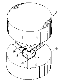
23 Fig. 1 shows a perspective view of the male die and
24 the female die used to form the spacer.
Fig. 2 is a top perspective view showing the spacer
26 placed on the edge of the female die to form the rear
27 protrusion.
28 Fig. 3 is a top perspective view showing the spacer
29 placed into the center of the female die to form the
remaining protrusions.
31 Fig. 4 is a perspective view showing the spacer in
32 completed form.
33 Fig. 5 is a perspective view showing the spacer in
34 its round ring form before it is placed in the dies.

2~.f~1~~6 ~ ,
3
1 Fig. 6 is a sectional view taken along line 6-6 of
2 Fig. 6.
3 Fig. 7 is a sectional view taken along line 7-7 of
4 Fig. 5.
Description of the Preferred Embodiment
6 The preferred embodiment herein described is not
7 intended to be exhaustive or to limit the invention to
8 the precise form disclosed. It is chosen and described
9 to explain the principles of the invention and its
application and practical use to enable others skilled in
11 the art to follow its teachings.
12 Referring to Figs. 5 and 7, a wire ring 2 is formed
13 from a round MIG stainless steel welding wire 10. The
14 wire is first wound around a cylindrical mandrel (not
shown) having a diameter substantially equal to the
16 desired diameter of the completed spacer. The wire is
17 then clipped or cut to remove a section or segment to
18 form an enlarged split 4 between spaced ends 18 of the
19 ring 2, as shown in Fig. 5.
The ring 2 is then initially placed in a stamping
21 die 12 by a worker 17 as shown in Fig. 2. The die 12 has
22 a cylindrical male part 6 and a cylindrical female part
23 8 as depicted in Fig. 1. The female part 8 has three
24 equal angularly spaced elongated grooves 14, generally U-
shaped in cross section, formed on its top surface 20.
26 Each groove 14 extends radially from the center of the
27 female part 8 to its outer edge. The male part 6 has
28 three equal angularly spaced elongated lands 16 which are
29 generally of an inverted U-shape in cross section formed
on its bottom surface 22. Each land 16 extends radially
31 from the center of the male part 6 to its outer edge.
32 The lands 16 and grooves 14 interfit when the die parts
33 are urged together as illustrated by the arrows in Figs.
34 2 and 3.

4
1 Ring 2 is first positioned at its center portion
2 between the female and male parts of the die 12 such that
3 the arc or edge 24 opposite from the split 25 of the
4 spacer is centered over a groove 14 of the female die as
seen in Fig. 2. The die parts are then pressed together
6 forming the center undulate protrusion 26 of the spacer
7 and also flattening the center portion of the spacer.
8 The male die part 6 is then moved away from the female
9 die part 8. The ring is then rotated 180° and centered
in the middle of the female die part with protrusion 26
11 fitted into a groove 14 as shown in Fig. 3. The parts of
12 the die are then pressed together flattening the
13 remainder of the ring and forming the remaining two
14 undulate protrusions 30 and 32 shown in Fig. 4.
Previously, when protrusions 26, 30 and 32 were
16 formed at one time in the die, by cold forming, the
17 stresses in the flattened spacer portions between
18 protrusions at the center protrusion 26 were locked in by
19 protrusions 30 and 32 at the center protrusions and were
subject to fracture. In the present invention by forming
21 the center protrusion first, the stress within the spacer
22 at the center protrusion is significantly relieved.
23 The above description is not to be considered as
24 limiting the invention to those details above-given,
which may be modified within the scope of the following
26 claims.

Dessin représentatif
Une figure unique qui représente un dessin illustrant l'invention.
États administratifs

2024-08-01 : Dans le cadre de la transition vers les Brevets de nouvelle génération (BNG), la base de données sur les brevets canadiens (BDBC) contient désormais un Historique d'événement plus détaillé, qui reproduit le Journal des événements de notre nouvelle solution interne.

Veuillez noter que les événements débutant par « Inactive : » se réfèrent à des événements qui ne sont plus utilisés dans notre nouvelle solution interne.

Pour une meilleure compréhension de l'état de la demande ou brevet qui figure sur cette page, la rubrique Mise en garde , et les descriptions de Brevet , Historique d'événement , Taxes périodiques et Historique des paiements devraient être consultées.

Historique d'événement

Description Date
Inactive : CIB désactivée 2011-07-27
Le délai pour l'annulation est expiré 2009-08-04
Inactive : CIB en 1re position 2009-02-23
Inactive : CIB attribuée 2009-02-23
Inactive : CIB expirée 2009-01-01
Lettre envoyée 2008-08-04
Inactive : CIB de MCD 2006-03-11
Inactive : TME en retard traitée 2003-11-04
Lettre envoyée 2003-08-04
Accordé par délivrance 2003-01-14
Inactive : Page couverture publiée 2003-01-13
Inactive : Taxe finale reçue 2002-10-28
Préoctroi 2002-10-28
Lettre envoyée 2002-09-03
Un avis d'acceptation est envoyé 2002-09-03
Inactive : Approuvée aux fins d'acceptation (AFA) 2002-08-21
Modification reçue - modification volontaire 2001-01-04
Inactive : Renseign. sur l'état - Complets dès date d'ent. journ. 2000-07-25
Lettre envoyée 2000-07-25
Inactive : Dem. traitée sur TS dès date d'ent. journal 2000-07-25
Exigences pour une requête d'examen - jugée conforme 2000-06-27
Toutes les exigences pour l'examen - jugée conforme 2000-06-27
Demande publiée (accessible au public) 1995-02-05
Déclaration du statut de petite entité jugée conforme 1993-08-04

Historique d'abandonnement

Il n'y a pas d'historique d'abandonnement

Taxes périodiques

Le dernier paiement a été reçu le 2002-07-10

Avis : Si le paiement en totalité n'a pas été reçu au plus tard à la date indiquée, une taxe supplémentaire peut être imposée, soit une des taxes suivantes :

  • taxe de rétablissement ;
  • taxe pour paiement en souffrance ; ou
  • taxe additionnelle pour le renversement d'une péremption réputée.

Veuillez vous référer à la page web des taxes sur les brevets de l'OPIC pour voir tous les montants actuels des taxes.

Historique des taxes

Type de taxes Anniversaire Échéance Date payée
TM (demande, 4e anniv.) - petite 04 1997-08-04 1997-06-02
TM (demande, 5e anniv.) - petite 05 1998-08-04 1998-07-10
TM (demande, 6e anniv.) - petite 06 1999-08-04 1999-06-24
Requête d'examen - petite 2000-06-27
TM (demande, 7e anniv.) - petite 07 2000-08-04 2000-07-21
TM (demande, 8e anniv.) - petite 08 2001-08-06 2001-07-03
TM (demande, 9e anniv.) - petite 09 2002-08-05 2002-07-10
Taxe finale - petite 2002-10-28
Annulation de la péremption réputée 2003-08-04 2003-11-04
TM (brevet, 10e anniv.) - petite 2003-08-04 2003-11-04
TM (brevet, 11e anniv.) - petite 2004-08-04 2004-07-22
TM (brevet, 12e anniv.) - petite 2005-08-04 2005-04-22
TM (brevet, 13e anniv.) - petite 2006-08-04 2006-06-01
TM (brevet, 14e anniv.) - petite 2007-08-06 2007-05-29
Titulaires au dossier

Les titulaires actuels et antérieures au dossier sont affichés en ordre alphabétique.

Titulaires actuels au dossier
GOODWIN A. LYCAN
Titulaires antérieures au dossier
S.O.
Les propriétaires antérieurs qui ne figurent pas dans la liste des « Propriétaires au dossier » apparaîtront dans d'autres documents au dossier.
Documents

Pour visionner les fichiers sélectionnés, entrer le code reCAPTCHA :


Pour visualiser une image, cliquer sur un lien dans la colonne description du document. Pour télécharger l'image (les images), cliquer l'une ou plusieurs cases à cocher dans la première colonne et ensuite cliquer sur le bouton "Télécharger sélection en format PDF (archive Zip)" ou le bouton "Télécharger sélection (en un fichier PDF fusionné)".

Liste des documents de brevet publiés et non publiés sur la BDBC .

Si vous avez des difficultés à accéder au contenu, veuillez communiquer avec le Centre de services à la clientèle au 1-866-997-1936, ou envoyer un courriel au Centre de service à la clientèle de l'OPIC.


Description du
Document 
Date
(aaaa-mm-jj) 
Nombre de pages   Taille de l'image (Ko) 
Page couverture 2002-12-10 1 29
Page couverture 1995-04-14 1 52
Revendications 1995-04-14 2 79
Revendications 2001-01-04 2 60
Dessin représentatif 1998-05-28 1 10
Dessin représentatif 2002-08-22 1 8
Description 1995-04-14 4 145
Abrégé 1995-04-14 1 10
Dessins 1995-04-14 4 48
Rappel - requête d'examen 2000-04-06 1 117
Accusé de réception de la requête d'examen 2000-07-25 1 177
Avis du commissaire - Demande jugée acceptable 2002-09-03 1 163
Avis concernant la taxe de maintien 2003-09-02 1 174
Quittance d'un paiement en retard 2003-11-18 1 166
Avis concernant la taxe de maintien 2008-09-15 1 171
Correspondance 2002-10-28 1 31
Taxes 1996-06-25 1 70
Taxes 1995-07-07 1 63