Sélection de la langue

Search

Sommaire du brevet 2102223 

Énoncé de désistement de responsabilité concernant l'information provenant de tiers

Une partie des informations de ce site Web a été fournie par des sources externes. Le gouvernement du Canada n'assume aucune responsabilité concernant la précision, l'actualité ou la fiabilité des informations fournies par les sources externes. Les utilisateurs qui désirent employer cette information devraient consulter directement la source des informations. Le contenu fourni par les sources externes n'est pas assujetti aux exigences sur les langues officielles, la protection des renseignements personnels et l'accessibilité.

Disponibilité de l'Abrégé et des Revendications

L'apparition de différences dans le texte et l'image des Revendications et de l'Abrégé dépend du moment auquel le document est publié. Les textes des Revendications et de l'Abrégé sont affichés :

  • lorsque la demande peut être examinée par le public;
  • lorsque le brevet est émis (délivrance).
(12) Brevet: (11) CA 2102223
(54) Titre français: SYSTEME GENERATEUR DE GAZ
(54) Titre anglais: GAS GENERATOR SYSTEM
Statut: Périmé et au-delà du délai pour l’annulation
Données bibliographiques
(51) Classification internationale des brevets (CIB):
  • B60R 21/264 (2006.01)
  • F42B 03/04 (2006.01)
(72) Inventeurs :
  • SCHMUCKER, ROBERT (Allemagne)
  • SIMON, JOSEF VICTOR (Allemagne)
  • FENDT-EDELBERG, RUTH (Allemagne)
  • HOGENAUER, ERNST (Allemagne)
(73) Titulaires :
  • TEMIC BAYERN-CHEMIE AIRBAG GMBH
(71) Demandeurs :
  • TEMIC BAYERN-CHEMIE AIRBAG GMBH (Allemagne)
(74) Agent: MACRAE & CO.
(74) Co-agent:
(45) Délivré: 1999-01-19
(86) Date de dépôt PCT: 1993-03-16
(87) Mise à la disponibilité du public: 1993-09-20
Requête d'examen: 1996-10-03
Licence disponible: S.O.
Cédé au domaine public: S.O.
(25) Langue des documents déposés: Anglais

Traité de coopération en matière de brevets (PCT): Oui
(86) Numéro de la demande PCT: PCT/EP1993/000603
(87) Numéro de publication internationale PCT: EP1993000603
(85) Entrée nationale: 1993-10-18

(30) Données de priorité de la demande:
Numéro de la demande Pays / territoire Date
P 42 08 843.7 (Allemagne) 1992-03-19
P 42 08 844.5 (Allemagne) 1992-03-19

Abrégés

Abrégé français

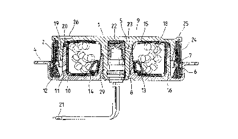
Dispositif à générateur de gas de construction légère, notamment d'un système de protection contre les chocs pour les occupants de véhicules, comprenant un espace central avec un allumeur pour une chambre de combustion qui l'entoure, destinée à du combustible solide, qui est entourée de son côté d'une chambre de filtration comportant des orifices de sortie pour l'insufflation de gaz dans un consommateur intercalé à la suite, contenant en combinaison: un boîtier composé d'une partie supérieure et d'une partie inférieure, assemblées par vis et entre lesquelles l'allumeur, le combustible et le filtre sont logés et fixés de telle sorte qu'ils sont séparés de l'extérieur de manière étanche et résistante à la pression, l'une de deux parties de boîtier assemblées par vis étant à peu près en forme de champignon en section transversale, ainsi que des modèles de filtres spéciaux des fixations permettant leur mise en place lors du vissage, et le guidage forcé prévu pour l'écoulement du gaz produit.


Abrégé anglais


Gas generator system of lightweight design, especially of an impact
protection system for occupants of vehicles, containing a central area with an
igniter for a combustion chamber enclosing the igniter for solid propellant,
which combustion chamber in turn is enclosed by a filter chamber with
discharge openings for inflating a downstream receiver, containing, in
combination: a housing, consisting of an upper part and a lower part, which
are screwed together, and which accommodate and hold between them the
igniter, the propellant, and the filter, so that they are sealed tightly and in a
pressure-proof manner from the outside, and that one of the two housing parts
that can be connected to one another has an approximately mushroom-shaped
cross section, as well as special filter designs and brackets for holding same
during screwing together, and the selected ducting for the flow of the gas
generated.

Revendications

Note : Les revendications sont présentées dans la langue officielle dans laquelle elles ont été soumises.


IN THE CLAIM:
1. A gas generator for impact protection systems for vehicle occupants,
comprising:
an essentially torodial housing formed of a housing upper part and a housing lower
part, said housing upper part having an inner wall with flow passages and having an outer
wall and said housing lower part having an inner wall and having an outer wall with outlet
flow passages, said inner walls defining an igniter chamber and a region between said inner
walls and said outer walls defining a propellant chamber whereby an essentially radial
principal direction of flow may be established, from inside said inner walls to outside said
outer walls, said housing lower part having a tray portion defining a filter receiving space,
opposite said outlet flow passages, an overhang portion of said housing upper part extending
over said tray portion, said inner housing walls each having threaded portions and said outer
housing walls each having threaded portions for connecting said housing upper part and said
housing lower part:
an igniter positioned in said igniter chamber;
solid propellant positioned in said propellant chamber;
coarse filter means positioned within said propellant chamber adjacent said outer wall
flow passages for initiating condensation of components of generated gas;
a guide plate positioned in said filter space and cooperating with said housing lower
part tray portion to form a separation chamber opposite said outlet flow passages, said guide

plate for directing the gas flow;
a fine filter cooperating with a retaining plate to form a retaining plate and filter
module, said retaining plate being positioned so that said retaining plate is held between
said tray portion and said overhang portion upon screwing together corresponding threaded
portions of said housing upper part and said housing lower part to connect said housing
upper part and said housing lower part and to fix said fine filter above said tray portion
wherein said fine filter is pressed at an upper end between said retaining plate and an outer
surface portion of said housing upper part outer wall and a lower end is pressed between
said retaining plate and said guide plate.
2. Gas generator according to claim 1, wherein said fine filter includes two outer
layers and an inner thicker ceramic fiber insert of non-woven ceramic material.
3. A gas generator according to claim 1, wherein metal wool is arranged in said
separation chamber for condensing and separating solid particles from propellant gas and
said guide plate and said outlet flow passages form ducting means for ducting gas flow such
that gas is discharged from said propellant chamber and first reaches said metal wool as a
turbulent flow and after being deflected by said guide plate is forced to flow into a discharge
chamber to said fine filter.
4. A gas generator according to claim 1, wherein said guide plate is designed
as a partition between said separation chamber and said fine filter, said fine filter being

located downstream of said guide plate.
5. A gas generator according to claim 1, wherein said retaining plate cooperates
with said tray portion and said overhang portion to define a filter chamber.
6. A gas generator for impact protection systems for vehicle occupants,
comprising:
an essentially torodial housing formed of a housing upper part and a housing lower
part, said housing upper part having an inner wall with flow passages and having an outer
wall and said housing lower part having an inner wall and having an outer wall with outlet
flow passages, said inner walls defining an igniter chamber and a region between said inner
walls and said outer walls defining a propellant chamber whereby an essentially radial
principal direction of flow may be established, from inside said inner walls to outside said
outer walls, said housing lower part having a tray portion defining a filter receiving space,
opposite said outlet flow passages, an overhang portion of said housing upper part extending
over said tray portion, said inner housing walls each having threaded portions and said outer
housing walls each having threaded portions for connecting said housing upper part and said
housing lower part;
an igniter positioned in said igniter chamber;
solid propellant positioned in said propellant chamber;
coarse filter means positioned within said propellant chamber adjacent said outerwall
flow passages for initiating condensation of components of generated gas;

a guide plate positioned in said filter space and cooperating with said housing lower
part tray portion to form a separation chamber including metal wool for condensation and
separating out solid particles from the generated gas, said guide plate directing the gas flow;
a fine filter cooperating with a retaining plate to form a plate and filter module, said
retaining plate being positioned so that said retaining plate is held between said tray portion
and said overhang portion upon screwing together corresponding threaded portions of said
housing upper part and said housing lower part to connect said housing upper part and said
housing lower part and to fix said fine filter above said tray portion, with an upper end of
said fine filter pressed between said retaining plate and an outer surface portion of said
housing upper part outer wall and with a lower end of said fine filter pressed between said
retaining plate and said guide plate, said retaining plate having a blow out opening adjacent
said fine filter, between said pressed upper end and said pressed lower end.
7. A gas generator according to claim 6, wherein said guide plate and said outlet
flow passages from ducting means for ducting gas flow such that gas is discharged from said
combustion chamber and first reaches said metal wool as a turbulent flow and after being
deflected by said guide plate is forced to flow into a discharge channel to said fine filter.
8. A gas generator according to claim 6, wherein said guide plate is designed as
a partition between said separation chamber and said fine filter, said fine filter being located
downstream of said guide plate.

9. A gas generator according to claim 6, wherein said fine filter includes two
outer layers and an inner thicker ceramic fiber insert of non-woven ceramic material.
10. A gas generator according to claim 6, wherein said retaining plate cooperates
with said tray portion and said overhang portion to define a filter chamber.

Description

Note : Les descriptions sont présentées dans la langue officielle dans laquelle elles ont été soumises.


~ ~0~3
Docket # 33,710
GAS GENERATOR SYSTEM
FIELD OF THE INVENTION
The gas generator according to the present invention is intended for a
protective device for occupants of motor vehicles, which device has a filter
chamber with filters for the gas ~low being discharged, wherein the filter
5 chamber is connected to the propellant chamber and communicates with it
through openings.
BACKGROUND OF THE INVENTION
Such gas generators have been known (cf., e.g., the Assignee's German
Patents 39,21,472 and 39,21,473).

~ l~aa~3
SUMMARY AND OBJECTS OF THE INVENTION
The object of the present invention is to deviate from the basis of the
sheet metal design, on which these and other prior-art gas generators are
la
A

~aa~3
based, and yet to meet the requirements, some of which are conflicting,
namely,
a) absolute tightness over a longer period of time,
b) pressure resistance for a high working pressure,
5 c) blowing out of a clean gas, which is cooled compared with the
combustion chamber temperature, from the blow-out openings on
the circumference,
d) light weight, and
e) low manufacturing costs.
The preferred application of the present invention is in gas generators
which are mounted, together with an air bag, in a steering wheel of a motor
vehicle in order to protect, e.g., a driver in the case of an impact, after ignition
initiation by a deceleration-sensitive switch.
According to the invention, a gas generator system of light weight
15 design is provided particularly for use as a protection system for vehicle
occupants. The gas generator is formed with a central area with an igniter
communicating with a combustion chamber for solid propellant. The
combustion chamber encloses the central area and the combustion chamber is
in turn enclosed by a filter chamber. The filter chamber includes discharge
20 openings for inflating a gas receiver element (such as an air bag) arranged
down stream.

a ~ 3
The gas generator is formed of an essentially torodial housing including
an upper part and lower part which is screwed together. The upper and lower
parts accommodate and hold between them the igniter, the propellent and the
filter and are sealed from the outside in tight and pressure proof manner. The
S upper part of the housing has an approximately mushroom-shaped cross
section forming a hollow stem or core area for receiving the igniter, the core
area including a screw connection portion for screwing the core area together
with the housing lower part. The approximately mushroom-shaped part of the
housing upper part being screwed together with the housing lower part at the
10 threaded portion at a circumference of the stem of the housing upper part and
additionally being screwed together at another circumferential area, located
radially outwardly from the circumference of the stem.
The various features of novelty which characterize the invention are
pointed out with particularly in the claims annexed to and forming a part of
15 this disclosure. For a better understanding of the invention, its operating
advantages and specific objects attained by its uses, reference is made to the
accompanying drawings and descriptive matter in which a preferred
embodiment of the invention is illustrated.
DETAILED DESCRIPTION OF THE PREFERRED
EMBODIMENT
The housing of the gas generator according to the invention consists of
2a
A`

d l~aa~ 3
light metal and is prepared especially according to injection molding,
diecasting, or extrusion processes with two parts 4 and 5, which are connected
to each other essentially by thread connection, wherein one of the parts forms
a lower part and the other forms an upper part. The upper part 5 is
S approximately mushroom-
2b

~l~a~3
shaped, while the lower part can be described as being of a cup-shaped or tray-
shaped design.
The upper part S has a central stem, which is hollow for accommodating
an igniting unit 1. The igniting unit is connected via a plug 21 to an electrical
S triggering circuit, which sends a signal for igniting an electrical igniter 1 after
recognition of an impact via a switch responding to a defined deceleration,
wherein the electrical igniter may be, e.g., a heating wire, which ignites an
igniting means 22 that is located in the hollow space of the stem of the upper
part S and may in turn be sealed or packaged, as shown, and whose packaging
10 bursts at a defined pressure in order to then allow a flame to propagate at
holes 23 into the propellant chamber for the pellets 18, here of annular shape.
This chain of ignition is not limited to two propellants, but such a chain of
ignition may also be formed by more than two substances. The lower part has
an innermost wall, formed by wall parts 8, which enclose the central area or
15 stem of the upper part 5 and can be screwed onto same by means of threads.
The lower part or cup 4 also has another ring, located farther on the
outside, with the wall area 11, which in turn can be screwed together with a
wall area 19 of the upper part 5 via threads. The lower part or tray 4 can in
turn be attached peripherally outside to a bracket of the steering wheel by
20 means of screws, likewise simultaneously with the interposition of the

~loaa~
air bag as an inflatable bag with its lowermost edge zone.
The wall areas in the lower part 4 and the upper part 5, which are
screwed together, have not only common threads inside and outside, but also
tapered tips, which are pressed into or press the other part, if desired, via a
S deformable ring 20, whose shape, size, and material are selected such as to
ensure suitable sealing. In addition, the pitch and design of the threads can
be selected to be such that these firmly interlock (nondetachable thread
connection). The threads may also be designed, at least partially, as self-
cutting threads. The wall areas to be screwed together may be designed
10 partially as elastic or flexible or slotted, just like, e.g., other sleeves or linings.
The solid propellant is filled into the said propellant chamber in the form of,
e.g., pellets 18 on pads 15, especially a nonwoven ceramic fiber material. It
would also be possible to use another suitable, temperature-resistant and
flexible material as a damping pad 14 or 15 at the bottom and/or at the top.
15 If the pellet charge does not or is not supposed to completely fill the space,
volume equalization can be ensured with metal wool inserts 13. The discharge
or overflow openings of the propellant chamber are designated by reference
numeral 16; these openings extend radially from the inside to the outside
toward the circumference, but are arranged, when viewed in their
20 circumference, obliquely toward the central axis. The openings 16 are oriented
such that the gas flow from the propellant chamber directly reaches
A

a3
a metal wool element 12 in the separation chamber in which liquid and solid
particles are separated from the gas. Liquid particles begin to condense
already at the coarse filter 10 in the propellant chamber in front of the passage
openings 16. The coarse filters 10 may be relatively wide-meshed screens,
S gratings or the like, preferably additionally covered with a somewhat softer,
finer fabric toward the inside, i.e., toward the propellant. Both the openings
16 for the overflow of the gas from the propellant chamber into the filter and
separation chamber, and the blow-out openings 24 may be sealed on the inside
with thin bursting films in the known manner in order to prevent moisture
from penetrating from the outside.
The two main parts 4 and 5 are screwed together by means of tool
holding fixtures 26 on the upper part 5 in order to introduce the necessary
force for screwing together. All propellants and filters must be inserted
beforehand in order for all parts to be clamped in tightly and in a pressure-
proof manner by means of the thread connection in a single operation.
Tightness under atmospheric pressure is ensured for several years, and the
bursting pressure or working pressure can be set depending on the require-
ments, excess pressure being especially > 300 atm or 3 x 10⁴ Megapascal, and
the excess temperature is especially > ca. 2500C.
Reference numeral 7 designates a guide plate for the flow, which is
A

~ l~aaa~
located in the filter chamber in the downstream direction behind the opening
16 and behind the glass wool filter 12, through which the gas flows, to separate
the particles and to condense liquid on the surface. The guide plate 7 is
shaped, on the one hand, such as to deflect the flow even multiple times and
5 to duct the flow in the filter chamber, and on the other hand, such as to form
a channel in the discharge direction, which distributes the gas over the filter
surface of the fine filter 2. The fine filter 2 is in contact with the guide plate
7, on the one hand, and is clamped or crimped in a groove 25 on the outer
circumference of the upper part 5, or is fixed in another manner by deforma-
10 tion after insertion of the filter 2 at 25. The fine filter 2 is in contact, on theother hand, with a plate 6, with the end of which it can be plugged into the
groove 25 and it can be inserted at the other end into the tray 4. The plate
6 and the sandwich-like metal-ceramic-metal filter together form a unit/module
2.
As is shown in the drawing, the stem of the upper part S is deformable
at its lower end, e.g., with a riveting or another, similar shaping tool, such that
the igniter 1 is held absolutely tightly therein. An additional fastening of this
type can also be performed at the inner or outer end of the tray 4. Part of the
thread section may be eliminated under certain circumstances in this case,
20 especially at the stem of the upper part S.

a~
-
The threads may be secured and sealed in various manners, e.g., by
means of adhesive or other securing means of prior-art type, such as insets,
claws, pins, etc., and lock nuts, e.g, at the lower end of the stem of the upperpart S.
Further variants of the exemplary embodiment are easily possible for
the person skilled in the art within the framework of the claims.
While a specific embodiment of the invention has been shown and
described in detail to illustrate the application of the principles of the
invention, it will be understood that the invention may be embodied otherwise
without departing from such principles.
A!l

Dessin représentatif
Une figure unique qui représente un dessin illustrant l'invention.
États administratifs

2024-08-01 : Dans le cadre de la transition vers les Brevets de nouvelle génération (BNG), la base de données sur les brevets canadiens (BDBC) contient désormais un Historique d'événement plus détaillé, qui reproduit le Journal des événements de notre nouvelle solution interne.

Veuillez noter que les événements débutant par « Inactive : » se réfèrent à des événements qui ne sont plus utilisés dans notre nouvelle solution interne.

Pour une meilleure compréhension de l'état de la demande ou brevet qui figure sur cette page, la rubrique Mise en garde , et les descriptions de Brevet , Historique d'événement , Taxes périodiques et Historique des paiements devraient être consultées.

Historique d'événement

Description Date
Inactive : CIB désactivée 2020-02-15
Inactive : CIB en 1re position 2019-11-28
Inactive : CIB attribuée 2019-11-28
Inactive : CIB expirée 2011-01-01
Inactive : CIB de MCD 2006-03-11
Le délai pour l'annulation est expiré 2001-03-16
Lettre envoyée 2000-03-16
Accordé par délivrance 1999-01-19
Inactive : Taxe finale reçue 1998-08-25
Préoctroi 1998-08-25
Lettre envoyée 1998-05-29
Un avis d'acceptation est envoyé 1998-05-29
Inactive : Approuvée aux fins d'acceptation (AFA) 1998-05-15
Inactive : Dem. traitée sur TS dès date d'ent. journal 1997-09-19
Inactive : Renseign. sur l'état - Complets dès date d'ent. journ. 1997-09-19
Toutes les exigences pour l'examen - jugée conforme 1996-10-03
Exigences pour une requête d'examen - jugée conforme 1996-10-03
Demande publiée (accessible au public) 1993-09-20

Historique d'abandonnement

Il n'y a pas d'historique d'abandonnement

Taxes périodiques

Le dernier paiement a été reçu le 1998-03-12

Avis : Si le paiement en totalité n'a pas été reçu au plus tard à la date indiquée, une taxe supplémentaire peut être imposée, soit une des taxes suivantes :

  • taxe de rétablissement ;
  • taxe pour paiement en souffrance ; ou
  • taxe additionnelle pour le renversement d'une péremption réputée.

Les taxes sur les brevets sont ajustées au 1er janvier de chaque année. Les montants ci-dessus sont les montants actuels s'ils sont reçus au plus tard le 31 décembre de l'année en cours.
Veuillez vous référer à la page web des taxes sur les brevets de l'OPIC pour voir tous les montants actuels des taxes.

Historique des taxes

Type de taxes Anniversaire Échéance Date payée
Requête d'examen - générale 1996-10-03
TM (demande, 5e anniv.) - générale 05 1998-03-16 1998-03-12
Taxe finale - générale 1998-08-25
TM (brevet, 6e anniv.) - générale 1999-03-16 1999-03-16
Titulaires au dossier

Les titulaires actuels et antérieures au dossier sont affichés en ordre alphabétique.

Titulaires actuels au dossier
TEMIC BAYERN-CHEMIE AIRBAG GMBH
Titulaires antérieures au dossier
ERNST HOGENAUER
JOSEF VICTOR SIMON
ROBERT SCHMUCKER
RUTH FENDT-EDELBERG
Les propriétaires antérieurs qui ne figurent pas dans la liste des « Propriétaires au dossier » apparaîtront dans d'autres documents au dossier.
Documents

Pour visionner les fichiers sélectionnés, entrer le code reCAPTCHA :


Pour visualiser une image, cliquer sur un lien dans la colonne description du document. Pour télécharger l'image (les images), cliquer l'une ou plusieurs cases à cocher dans la première colonne et ensuite cliquer sur le bouton "Télécharger sélection en format PDF (archive Zip)" ou le bouton "Télécharger sélection (en un fichier PDF fusionné)".

Liste des documents de brevet publiés et non publiés sur la BDBC .

Si vous avez des difficultés à accéder au contenu, veuillez communiquer avec le Centre de services à la clientèle au 1-866-997-1936, ou envoyer un courriel au Centre de service à la clientèle de l'OPIC.


Description du
Document 
Date
(aaaa-mm-jj) 
Nombre de pages   Taille de l'image (Ko) 
Abrégé 1995-05-12 1 66
Revendications 1995-05-12 5 322
Dessins 1995-05-12 1 76
Description 1995-05-12 7 484
Description 1996-12-02 10 256
Abrégé 1996-12-02 1 24
Revendications 1996-12-02 5 159
Dessin représentatif 1999-01-18 1 24
Avis du commissaire - Demande jugée acceptable 1998-05-28 1 164
Avis concernant la taxe de maintien 2000-04-12 1 178
Correspondance 1998-08-24 1 33
PCT 1993-10-17 21 960
Taxes 1996-03-06 1 35
Taxes 1995-03-13 1 41
Taxes 1997-03-16 1 58