Sélection de la langue

Search

Sommaire du brevet 2102336 

Énoncé de désistement de responsabilité concernant l'information provenant de tiers

Une partie des informations de ce site Web a été fournie par des sources externes. Le gouvernement du Canada n'assume aucune responsabilité concernant la précision, l'actualité ou la fiabilité des informations fournies par les sources externes. Les utilisateurs qui désirent employer cette information devraient consulter directement la source des informations. Le contenu fourni par les sources externes n'est pas assujetti aux exigences sur les langues officielles, la protection des renseignements personnels et l'accessibilité.

Disponibilité de l'Abrégé et des Revendications

L'apparition de différences dans le texte et l'image des Revendications et de l'Abrégé dépend du moment auquel le document est publié. Les textes des Revendications et de l'Abrégé sont affichés :

  • lorsque la demande peut être examinée par le public;
  • lorsque le brevet est émis (délivrance).
(12) Brevet: (11) CA 2102336
(54) Titre français: METHODE DE FABRICATION DE ROUES FORGEES D'UN SEUL TENANT
(54) Titre anglais: PROCESS OF MANUFACTURING ONE-PIECE FORGED WHEELS
Statut: Périmé et au-delà du délai pour l’annulation
Données bibliographiques
(51) Classification internationale des brevets (CIB):
  • B21H 1/02 (2006.01)
  • B21K 1/28 (2006.01)
  • B21K 1/38 (2006.01)
  • B23P 15/00 (2006.01)
  • B60B 3/02 (2006.01)
(72) Inventeurs :
  • MATOSSIAN, HOVHANNES AGOP (Etats-Unis d'Amérique)
  • MATSON, GEORGE A. (Etats-Unis d'Amérique)
(73) Titulaires :
  • NI INDUSTRIES, INC.
(71) Demandeurs :
  • NI INDUSTRIES, INC. (Etats-Unis d'Amérique)
(74) Agent: SMART & BIGGAR LP
(74) Co-agent:
(45) Délivré: 1999-12-21
(22) Date de dépôt: 1993-11-03
(41) Mise à la disponibilité du public: 1994-05-05
Requête d'examen: 1994-06-10
Licence disponible: S.O.
Cédé au domaine public: S.O.
(25) Langue des documents déposés: Anglais

Traité de coopération en matière de brevets (PCT): Non

(30) Données de priorité de la demande:
Numéro de la demande Pays / territoire Date
07/971,378 (Etats-Unis d'Amérique) 1992-11-04

Abrégés

Abrégé anglais


A one-piece forged vehicle wheel manufactured from a single
piece of metal material thereby forming a strong, lightweight
wheel. The wheel is manufactured as a result of extrusion, forging
and machining a metal blank to provide the desired contours and
configuration. The integral nature of the rim and hub eliminates
the need to weld components, improving integrity while reducing
manufacturing costs.

Revendications

Note : Les revendications sont présentées dans la langue officielle dans laquelle elles ont été soumises.


CLAIMS
1. Process of manufacturing a one-piece wheel for a vehicle
comprising:
forming a ring of material adapted to comprise the one-piece
wheel, said ring including an inner radial surface and an outer
radial surface;
extruding a rim section of said wheel coaxially to said ring
while supporting said inner radial surface of said ring;
removing said inner radial support of said ring and forging a
hub section of said wheel; and
forming the contour of said rim section.
2. The process as defined in claim 1 wherein said step of
forging said hub section of said wheel forms alternating convex and
concave zones radially spaced on said hub section.
3. The process as defined in claim 2 and comprising the
further step of machining said concave zones of said hub section to
form openings in said hub section.
4. The process as defined in claim 3 wherein said concave
zones of said hub section are machined from an inboard side of said
wheel to form said openings in said hub section.
5. The process as defined in claim 1 wherein said step of
forming the contour of said rim section comprises the steps of:
(a) mounting said wheel in a retaining mold with said rim
section disposed outwardly; and
(b) running a roller tool along said rim section whereby said
rim section accepts the contour of said retaining mold and
roller tool.
7

6. The process as defined in claim 5 wherein said retaining
mold is rotated with said wheel therein such that said rim section
passes between said roller tool and retaining mold to receive the
contour thereof.
7. The process as defined in claim 1 wherein said ring is
hot extruded to form said rim section coaxial to said ring.
8. The process as defined in claim 1 wherein said hub
section is forged radially inward.
9. Process of manufacturing a one-piece wheel for a vehicle
comprising:
forming a ring of metal material, said ring including an inner
radial surface and an outer radial surface;
supporting said inner radial surface of said ring while
extruding a rim section longitudinally coaxial to said ring, said
inner radial support preventing radial inward flow of said metal
material during extrusion of said rim section;
removing said inner radial support of said ring and forging a
hub section of said wheel, said hub section being forged radially
inwardly and including a plurality of concave zones radially spaced
on said hub section; and
applying a roller tool to said rim section to form the contour
of said rim section.
10. The process as defined in claim 9 wherein said concave
zones of said hub section are machined from an inboard side of said
wheel to form said openings in said hub section.
11. The process as defined in claim 10 wherein said step of
forming the contour of said rim section includes the steps of:
(a) mounting said wheel in a rotatable retaining mold with
said rim section disposed radially outwardly in close
proximity to an outer molding surface of said rotatable mold;
8

(b) applying a roller tool to said rim section, said roller
tool having a mating configuration to said outer molding
surface; and
(c) rotating said retaining mold while applying pressure to
said rim section through said roller tool whereby said rim
section accepts tie contour of said retaining mold and roller
tool.
12. The process as defined in claim 9 and comprising the
further step of drilling lug holes in said hub section following
forging of said hub section.
13. The process as defined in claim 9 wherein said ring is
made of an aluminum metal whereby said process forms a one-piece
aluminum wheel.
9

Description

Note : Les descriptions sont présentées dans la langue officielle dans laquelle elles ont été soumises.


\ ',
PROCESS OF MANUFACTURING
ONE-PIECE FORGED WHEELS
Background Of The Invention
I. ~,ield of the Invention
This invention relates to a process for manufacturing vehicle
wheels and, in particular, to a process for manufacturing one-piece
forged aluminum wheels far use in vehicles.
II. Description of the Prior Art
In the past, wheels for vehicles have been cast or forged of
multiple pieces and then assembled to form the wheel. In the
typical construction, the central disc or hub is formed
independently of the rim which itself may be formed of one or more
components. The components of the wheel are then assembled and
welded together to form an integral assembly. The wheel typically
comprises the central disc or hub having a plurality of vent
openings and a plurality of lug openings to facilitate mounting of
the wheel to the vehicle axle. Attached to the peripheral edge of
the disc is the rim which retains the vehicle tire, particularly
the sealing bead of the tire. The rim must be free of sharp edges
to prevent damage to the tire and must be airtight to maintain tire
pressure.
The prior known multiple piece wheels have several
disadvantages including cost of manufacturing, quality concerns
resulting from the mating engagement of the central disc with the
rim, and deterioration of the weld joints particularly when plating
of the assembled wheel is improperly conducted. The nature of the
multiple component wheel, which requires multiple manufacturing
stations, lends itself to quality problems and deterioration of the
wheel assexably.
Summary Of The Present Invention
The present invention overcomes the disadvantages of the prior
known vehicle wheels by providing a method of manufacturing a one-
piece forged wheel from a single piece of metal stock.

The manufacturing process begins with a ring-shaped blank cut
from tube stock of aluminum or forged and machined into the donut
shape desired. The rim section of the wheel is extruded coaxially
from the ring while containing the inward radial flow along the hub
section. By containing the radial inward flow during extrusion of
the rim section, much smaller tonnage presses can be used since
without such containment the material will flow across the hub face
area and consume all of the force of a smaller press before the rim
can extrude longitudinally to a sufficient length. Once the rim
section is properly extruded, the containment tooling is no longer
necessary and the hub design can be forged radially inwardly to its
desired configuration.
As the hub is forged, alternating convex and concave areas are
formed radially about the central hub opening. Subsequently, the
concave areas are machined away from the interior side of the wheel
to form the vent openings in the wheel. This leaves the convex
areas as ''spokes" of the wheel and avoids the use of piercing tools
in the hub face. Alternatively, the vent openings or windows may
be pierced into the wheel face using an appropriate tool.
With the hub section substantially formed, the forged wheel
assembly will include inboard and outboard sections of the rim
flared away from the axis of the wheel. The wheel is clamped in a
rotary tool and the wheel is rotated about its axis. As the wheel
spins, a. roller is applied to the rim to form the r:im configuration
according to the configuration of the roller and the tool mold. In
this manner, the rim contour is precisely formed without machining
resulting in a thin, strong rim and a lightweight wheel. The
extrusion, forging and rolling processes form a one-piece wheel
with improved durability and reduced weight.
Other objects, features and advantages of the invention will
be apparent from the following detailed description taken in
connection with the accompanying drawings.
2

CA 02102336 1999-07-07
This invention relates to a process of manufacturing a one-piece wheel for
a vehicle comprising: forming a ring of material adapted to comprise the one-
piece
wheel, said ring including an inner radial surface and an outer radial
surface; extruding
a rim section of said wheel coaxially to said ring while supporting said inner
radial
surface of said ring; removing said inner radial support of said ring and
forging a hub
section of said wheel; and forming the contour of said rim section.
2a

~1 ~;?'~'3
brief Description Of The Drawincr
The present invention will be more fully understood by
reference to the following detailed description of a preferred
embodiment of the present invention when read in conjunction with
the accompanying drawing, in which like reference characters refer
to like parts throughout the view and in which:
FIGURES 1 through 12 show the process steps of forging a one-
piece wheel embodying the present invention;
FIGURE 13 is an enlarged cross-sectional perspective of the
.wheel hub showing the concave and concave areas of the hub machine
to form vent openings in the hub;
FIGURE 14 is a cross-sectional view of the roller press in
the open position with the wheel disposed therein; and
FIGURE 15 is a cross-sectional view of the roller press with
the wheel clamped therein for forming the rim configuration.
Detailed Description Of A Preferred
Embodiment Of The Present Invention
Referring first to Figures 1 through 12, there are shown the
different configurations of the one-piece forged wheel of the
present invention as it is processed from a metal blank to the
finished wheel. The manufacturing process of the present invention
forms an integral wheel whereby welding of the hub to the rim is
eliminated. Additionally, the wheel is manufactured such that
smaller tonnage presses can be utilized to extrude and forge the
wheel. The process precisely forms the cantours of the wheel to
create very thin yet strong rims resulting in a lightweight wheel
with improved integrity.
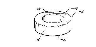
Figures 1 and 2 show an aluminum blank 10 in the form of a
ring or donut from which the wheel is forged. The blank 10 is
preferably cut to proper length from a tube of aluminum stock. As
an alternative, the ring-shaped blank may be produced by a forging
operation which flattens a section of solid aluminum bar and then
piercing or boring the forged blank to remove the center of the
ring. For reference purposes, the blank 10 has an inner surface
3

~~ ~~.~,~ jt~
12, an outer radial surface 14, an outboard side 16, and an inboard
side 18 all of which correspond to the reference position of the
finished wheel. A rim section 20 is extruded coaxial to the axis
of the ring 10 while containing the inward radial surface 12 along
the hub area (arrows a). ~y containing the inward radial surface
12 a much smaller tonnage press can be utilized since the tonnage
requirement is a factor of the cross-sectional area perpendicular
to the press force. Without such containment, the material would
tend to flow radially inwardly across the hub face and "consume"
all of the force of a smaller press before the rim section 20 could
be extruded to a sufficient length (Fig. 3). In a preferred
embodiment, the rim section 20 is hot extruded to the desired
length and then trimmed to the required length (Fig. 4).
After the rim section is properly extruded and trimmed, the
containment tooling is no longer needed and may be removed from
forging of the hub section 22 (Fig. 5). The hub section 22 is hot
forged to the desired configuration in accordance with the
configuration of the mold. Typically, the hub section 22 will
include a hub opening 24 and a mounting face 26 surrounding the
opening 24 to facilitate mounting of the wheel to the axle of the
vehicle. Any ornamental configuration is forged in the peripheral
area 28 between the rim section and the mounting face 26. In a
preferred embodiment of the present invention, alternating concave
30 and convex 32 zones are forged radially about the hub face 22 as
best shown in Fig. 13. In order to avoid the use of pierce tooling
which may deform the hub face, the concave zones 30 are utilized to
form vent openings or windows 34 in the hub section 22. The
concave zones 30 are machined away from the inboard side 18 of the
hub section 22 using an appropriate machining tool T until the
appropriate opening 34 is formed at the bottom of the concave zone
20. The alternating openings 34 and convex zones 32 provide the
appearance of spoke-like bodies ~n the hub 22 of the wheel. In an
alternative embodiment, the wheel face may be formed with
alternating sections of thick and thin material wherein the thin
4

sections are pierced to form the windows creating vent openings in
the wheel 10.
With the hub section 22 formed and machined, the inboard leg
40 and the outboard leg 42 of the rim section 20 are flared
radially outwardly as shown in Fig. 6. The wheel 10 is then placed
in the mandrel of a spinning machine M (Figs. 14 and 15) and
clamped into position by clamping against the hub section 22 of the
wheel. The spinning machine M includes a molding surface S which
incorporates the contour of the molded rim section. Similarly, a
roller tool R has a mating molding surface S' . With the wheel
clamped in the machine M, the wheel is spun about its axis and the
roller tool R is applied to the rim section 20 to precisely form
the rim contour. As a result, no machining is necessary except to
trim the ends 40 and 42 and a very thin yet strong rim is produced
using the extrusion and rolling processes as shown in Figure 7. In
applications where extremely close tolerances are required, the rim
rolling operation may be conducted as a two-step process wherein a
preliminary rolling operation is followed by a solution heat
treatment operation and a final rolling operation. The final
rolling operation removes the distortional effects of the solution
heat treatment bath.
Once formed, final machining of the wheel is conducted. The
outboard side of the hub face 26 is machined to the proper contour
(Fig. 8) and the inboard side of the hub section 22 is machined as
required (Fig. 9). Lug holes 44 are drilled in the hub face 26
(Fig. 10) and a valve hole 46 is drilled in through inboard leg 42
of the rim section 20 (Fig. 11). Finally, the wheel 10 is polished
and a clear coat finish is applied forming the finished product as
shown in Figure 12. Thus, the process of the present invention
produces a one-piece forged wheel 10 incorporating a thin yet
strong rim resulting in a lightweight wheel. Welding of the hub to
the rim is eliminated since both are integrally formed from a
single piece of metal stock.
The foregoing detailed description has been given for
clearness of understanding only and no unnecessary limitations

y ~~ ~~'~35
should be understood therefrom as some modifications will be
obvious to those skilled in the art without departing from the
scope and spirit of the appended claims.
What is claimed is:
6

Dessin représentatif
Une figure unique qui représente un dessin illustrant l'invention.
États administratifs

2024-08-01 : Dans le cadre de la transition vers les Brevets de nouvelle génération (BNG), la base de données sur les brevets canadiens (BDBC) contient désormais un Historique d'événement plus détaillé, qui reproduit le Journal des événements de notre nouvelle solution interne.

Veuillez noter que les événements débutant par « Inactive : » se réfèrent à des événements qui ne sont plus utilisés dans notre nouvelle solution interne.

Pour une meilleure compréhension de l'état de la demande ou brevet qui figure sur cette page, la rubrique Mise en garde , et les descriptions de Brevet , Historique d'événement , Taxes périodiques et Historique des paiements devraient être consultées.

Historique d'événement

Description Date
Inactive : CIB de MCD 2006-03-11
Le délai pour l'annulation est expiré 2002-11-04
Lettre envoyée 2001-11-05
Accordé par délivrance 1999-12-21
Inactive : Page couverture publiée 1999-12-20
Lettre envoyée 1999-07-28
Exigences de modification après acceptation - jugée conforme 1999-07-28
Inactive : Taxe finale reçue 1999-07-07
Modification après acceptation reçue 1999-07-07
Inactive : Taxe de modif. après accept. traitée 1999-07-07
Préoctroi 1999-07-07
Lettre envoyée 1999-04-06
month 1999-04-06
Un avis d'acceptation est envoyé 1999-04-06
Inactive : Dem. traitée sur TS dès date d'ent. journal 1999-03-30
Inactive : Renseign. sur l'état - Complets dès date d'ent. journ. 1999-03-30
Inactive : Approuvée aux fins d'acceptation (AFA) 1999-03-12
Inactive : CIB enlevée 1999-03-12
Inactive : CIB en 1re position 1999-03-12
Toutes les exigences pour l'examen - jugée conforme 1994-06-10
Exigences pour une requête d'examen - jugée conforme 1994-06-10
Demande publiée (accessible au public) 1994-05-05

Historique d'abandonnement

Il n'y a pas d'historique d'abandonnement

Taxes périodiques

Le dernier paiement a été reçu le 1999-09-21

Avis : Si le paiement en totalité n'a pas été reçu au plus tard à la date indiquée, une taxe supplémentaire peut être imposée, soit une des taxes suivantes :

  • taxe de rétablissement ;
  • taxe pour paiement en souffrance ; ou
  • taxe additionnelle pour le renversement d'une péremption réputée.

Les taxes sur les brevets sont ajustées au 1er janvier de chaque année. Les montants ci-dessus sont les montants actuels s'ils sont reçus au plus tard le 31 décembre de l'année en cours.
Veuillez vous référer à la page web des taxes sur les brevets de l'OPIC pour voir tous les montants actuels des taxes.

Historique des taxes

Type de taxes Anniversaire Échéance Date payée
TM (demande, 4e anniv.) - générale 04 1997-11-03 1997-09-19
TM (demande, 5e anniv.) - générale 05 1998-11-03 1998-09-24
1999-07-07
Taxe finale - générale 1999-07-07
TM (demande, 6e anniv.) - générale 06 1999-11-03 1999-09-21
TM (brevet, 7e anniv.) - générale 2000-11-03 2000-10-03
Titulaires au dossier

Les titulaires actuels et antérieures au dossier sont affichés en ordre alphabétique.

Titulaires actuels au dossier
NI INDUSTRIES, INC.
Titulaires antérieures au dossier
GEORGE A. MATSON
HOVHANNES AGOP MATOSSIAN
Les propriétaires antérieurs qui ne figurent pas dans la liste des « Propriétaires au dossier » apparaîtront dans d'autres documents au dossier.
Documents

Pour visionner les fichiers sélectionnés, entrer le code reCAPTCHA :


Pour visualiser une image, cliquer sur un lien dans la colonne description du document (Temporairement non-disponible). Pour télécharger l'image (les images), cliquer l'une ou plusieurs cases à cocher dans la première colonne et ensuite cliquer sur le bouton "Télécharger sélection en format PDF (archive Zip)" ou le bouton "Télécharger sélection (en un fichier PDF fusionné)".

Liste des documents de brevet publiés et non publiés sur la BDBC .

Si vous avez des difficultés à accéder au contenu, veuillez communiquer avec le Centre de services à la clientèle au 1-866-997-1936, ou envoyer un courriel au Centre de service à la clientèle de l'OPIC.

({010=Tous les documents, 020=Au moment du dépôt, 030=Au moment de la mise à la disponibilité du public, 040=À la délivrance, 050=Examen, 060=Correspondance reçue, 070=Divers, 080=Correspondance envoyée, 090=Paiement})


Description du
Document 
Date
(aaaa-mm-jj) 
Nombre de pages   Taille de l'image (Ko) 
Revendications 1995-04-07 3 138
Abrégé 1995-04-07 1 21
Dessins 1995-04-07 4 127
Description 1995-04-07 6 284
Dessins 1999-03-02 4 102
Revendications 1999-03-02 3 100
Description 1999-07-06 7 297
Dessin représentatif 1998-08-20 1 6
Dessin représentatif 1999-12-06 1 4
Avis du commissaire - Demande jugée acceptable 1999-04-05 1 164
Avis concernant la taxe de maintien 2001-12-02 1 178
Correspondance 1999-07-06 2 57
Taxes 1996-09-29 1 82
Taxes 1995-09-26 1 78
Correspondance de la poursuite 1994-06-09 1 45
Correspondance de la poursuite 1999-01-20 2 42
Demande de l'examinateur 1998-07-20 2 53
Courtoisie - Lettre du bureau 1994-08-02 1 43
Courtoisie - Lettre du bureau 1994-01-13 1 37
Courtoisie - Lettre du bureau 1995-01-25 1 24