Note : Les descriptions sont présentées dans la langue officielle dans laquelle elles ont été soumises.
BAÇKGI;~3::)lJND OF ll~l\/ENTIONI
1. Field of Invention
This invention relates to a low profile temporary, continuous water flow
crossover device that allows vehicle traffic to cross over while maintaining water
flow and pressure to output.
2. Description o~ Prior ~ct
Fire departments commoniy use crossover devices when water hoses must
be laid over roadways. These cross-over devices serve two purposes:
1. To protect hoses from damage caused from vehicles.
2. To maintain a constant rate of water flow.
3. To allow traffice to pass over.
, ~:
U.S. Patent No. 2,299,356 to Strohm et al. (1942), discloses a utility crossover ~j~
device which comprises of a mat composed of resilient material, such as rubber.I ~`
One side of the pad is provided with a plurality of longitudinal slots for carrying
water hoses, cables, pipes etc. The pads are formed in sections adapted to be
handlecl by one person and are arranged to be placed adjacent each other to
form a crossover of any desired extent. Ramp por7ions are formed on the
outermost edges of the crossover device. Although the Strohm et al. device has
advantages associated ~herewith, one of the disadvantages associated
therewith is thcrt the rubber material is relatively heavy and compressible and thus `
unable to supporl relatively heavy loads. In adclition, the devise is relativelyexpensive and bulky in size.
U. S. Patent No. 3,888,186 to Juntzsch et al. (1975) disclose a portable
crossover device made of high strength elas~omeric ma~erial which includes a
single U- shaped channel or recess and a s~ripped insert of elastomeric materialplaced over the hose or cable to prevent debris frorn damaging the hose or
cable. The crossover unit has ramps on each side to en~age a vehicle.
~ ~ o
2 ~ :~
Generally speaking, crossover units of elastomeric materials lencl
themselves readily to fabrication by customary molding techniques. However,
owing to the severily of the loads passing thereover, the hose or cable should not ~ :
shoulder any appreciable percentage of the ioad. The unit must be designed so
that the weight of the traversing vehicles does not deform the unit to such a
degree that the load is applied to the hose. If the elas~omeric material used in :
the uni~ construction is quite resilient, then the usual procedure is to make the unit
sufficiently thick so that, when partially comprçssed it will not be deformed tosuch an extent so as to cause any sizable portion of the load to press against the
hose. Any increase in unit height or thickness provides more of a ~bumpU over
which vehicles must pass. The bumping action can be moderated by having ~ :inclined ramps that slope oniy gradually upwardly, but then the width of the unit is
unduly increased. While H is possible to make the crossover unH relatively rigid,
the lessened resiliency renders them fragile and the inability to flex when placed
on uneven grouncl resuit in breakage when subjected to sizable crossover loads.
~ .
`,
SllMMARY OF PRESENT INVENTION
Fire fighters have to lay their hoses over roadways to get water to the
structure fire if the water hydrants are on the opposing side. In these cases, it
may not be practical to close a roadway as it may be an important thoroughfare.
Fire fighters usually use an assortmer~t of hose bridges (hose cross over devices)
to allow vehicles to cross over the hoses. All methods currently in use, requirevehicles to slow down considerably before crossing. Some vehicles that are low
to the ground or are too heavy, usually cannot crossover. ~he result in all cases is
traffic congestion. My invention allows all traffic to cross over at higher speeds,
thus reducing traffic congestion. This also enables other emergency vehicles to
access the scene more expediently. Furthermore, this cross-over device has the
additional advantages in that:
it is easy to install;
~ requires low supervision;
9~ it does not jeopardize fire hoses;
it prevents traffic congestion: :
it allows all traffic to crossover;
it allows traffic to cross over at higher speeds;
i~ is not damaged if vehicles brake on it;
it aliows constant water pressure and flow on the output connections;
it has self alerting signs to inforrn drivers of Hs presence;
it allows other emergency vehicles to get to the site as there is less
traffic congestion;
it is easy to roll up and store;
it may be dropped out of a fire truck from the normal operation height
for faster installation.
. .
'
:~:
. ~.
,::
' ~
Currently, cross-over devices are generally similar in design. A housing ~ ~:
constructed of various types of materials cover the hose with ramps to allow
traffic to pass over. While these types of devices serve their purpose, they have
numerous disaclvantages:
a) Do not allow for moderate vehicle speeds - resuHing in traffic
congestion.
b) A number of devices are needed for all widths of vehicles to cross over.
c) It is unrealistic to place current crossover devices over every foot of
hose on the roadway, therefore hoses would be exposed to the ~; -
roadway. :
d) Generally, current devices need constant supervision.
e) Current devices are not designed to be placed over roadway where
accidental runnover by a vehicle may occur.
f) In general, current crossover devices comprise of a ramp. If vehicles
rniss the ramp and runover the hose the decreased water flow would
not be desirable.
: :'
Several objects and advantages of the present invention are~
a) to produce a water hose crossover device that is low profile;
b) to produce a water hose crossover device that provides a safe ;
crosslng for vehicles traveling at higher speeds;
c) to produce a water hose crossover device that reduces traffic
congestion on busy roads;
d) to produce a water hose crossover device that allows low profile -
vehicles to cross over; ~
e) to produce a water hose crossover device that will not be ;
damaged if braked on;
f) to produce a water hose crossover device that does not place
fire hose on roadway. Only unH hoses are at risk.
;~........................................................................ ~
IBRIEF DESCRIP~ION OF THE DRAWINGS ~ ~:
For a better understanding of the invention as well as other objects and
further features thereof, reference is made to the following description which is to
be read in conjunction with the accompanying drawings wherein:
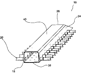
Figur.e 1 is a side view of an embodiment of the crossover device.
Figure lP~ is a cross sectional view illustrating the internal construction of the
manifolds.
Figure 2 is a top view of Figure 1.
Figure 3 is a perspective view of Figure 1.
Figure 4 is a perspective view of the top covers.
Figure 4A is a perspective view of the bot~om cover.
Re~er~nce Num~rc~ls in Dr~winçls
''
12 manifold 14 manifold
16 intake/dischargefitting 17 facingsideofmanifold
18 smaller diameter hose connection 20 smaller diam~ter hoses
22 centremanifold 24 sidesofcentremanifold
~ 26 top covers 28 small water vents
:~ 30 bv1tomcover 32cautionflugs
. 34 handles 36 upwardlyinclinedside
` 38 bottomsideof manifold 40 topsideof manifold
42 flatstraphole
,
:~
.
.
DESCRFPTIOI~F C)F TI~FE Fi~FVEl\FTlON
Referring now to the Figures, the embodiment of the present invention ~.:
shown, the crossover device 10 (the use of the term "crossover device~ is meant
to encompass the other terms used to describe the same device) comprises
opposed manifolds 12 and 14. As may be seen in Figure 1, each manifold has an
intake or discharge fi~ing 16.
- One side 17 of each manifold 12 and 14 comprises a plurality of smaller
diameter hose connections 18. The smaller diameter hose connections are
parallel with each other as may be seen in Figure 1. Each of the smaller diameter
hose connections merges with small diameter high pressure hoses 20 that lay
parallel to the ground surface as may be seen in Figure 1. The high pressure
hoses are preferably made of a highly wear resistant rnaterial that would return to ~ :
its original shape after compression by vehicles. These smaller diameter hoses
have a total sum flow capacity greater than the intake or discharge fittings 16. :
The length of the high pressure smaller diameter hoses ~0 between manifolds 12,
14 and 22 are the same, but would be of sufficient length to allow two lanes of
traffic to cross over at relatively high speed. The unit would allow two lanes of
traffic to cross over, one between manifold 12 and 22 and another between 22 `;~and 14~
Manifolds 12, 14 and 22 of the present invention comprises a hollow body,.'
` constructed from material that withstands both internal water pressure and
external force of a heavy vehicle inadve~tently crossing over it. Water flow
would not be compromised while in this manifold-. Each manifold comprises a ~.bottom and top general horizontal surface portion 38 and 40 as seen in Figure 1 A
and a surface 3~ which is inclined upwardly. Manifolds 12 and 14 differ from
manifold 22 as they comprise an intake or discharge fitting~ As illustrated in Figure
lA, manifold 22 comprises a plurality of smaller diameter hose connec;tions on
both sides 24.
~'
,
~,
The crossover unit 10 also comprises a centre manifold 22, constructed
from material that wi~hs~ands both internal water pressure and external force of a
heavy vehicle inadvertently crossing over it. Water flow would not be
compromised while in this manifold. Both sides 24 of the centre manifoid
comprise a plurality of smaller diameter hose connections. These smaller
diameter hose connections merge with a high pressure hose 20. The top
surfaces of the smaller diameter hoses are protected by two top covers 26 as
shown in Figure 4, which are made of a high wear, resiliently flexible material. The
top covers provide two functions, i.e., preventing debris from accumulation on
top of the smalier diameter hoses which otherwise would damage the hoses and,
when sprayed with water, reduces hose damage from vehicular braking.
, ~ ,
A feature of the invention is the small water vents 28 located on the top
side of each manifoid 12, 14 and 22. These water vents, capable of withstanding
vehicles clriving or braking, would provide a constant stream of water on the top
cover. The top cover is made of a material that, when wet, becomes somewhat
siippery. This slippery surface resists damage from vehicle operation. These water
vents can be removed and replaced with a plug during freezing temperatures. ~ i
This would prevent ice build-up on top cover.
A bot~om cover 30 as shvwn in Figure 4A would prevent debris from
accumulating underneath the hoses and might otherwise damage the smaller
diameter hoses. The bollom cover would also prevent smaller diameter hoses
from contact with the ground surface that might resul~ in damage. Top covers 26
and bo~om cover 30 are altached to each other by a variety of methods (i.e.
flat strap) looped through hoies 42.
~.~
Another feature ~ the present invention is the optional, detachable pop
up UCoutionN flags 32 located on each manifold 12, 14 and 22 as shown in Figure
3. These caution flags are made of a resiliently flexible material. This material
would allow litlle damage if inadvertently run over by a vehicle crossing over.
These caution flags would alert vehicle drivers to the crossover device.
.
.~
- 3 -
Manifolds 12, 14 and 22 would comprise two handles 34 as shown in Figure
2 on each side 36. For storage, the present invention rolls from manifold 1~
toward manifold 14 or vice versa. The handles allow for two people to carry the
device easily.
The present invention thus provides a crossover device that is easily stored
and handled and due to the pop up "Caution" flags and low vertical profile,
re~uires relatively little supervision.
Opera~ion .
The un'H is rolled out across the roadway. Water is introduced at one end
16. The water enters a manifoid 12 that divides it into several smaller diarneter
connections 18 which lead into high pressure hoses 20. It is upon these hoses that
vehicles cross over. The hoses are of sufficient length to allow all traffic to cross
over. The small diameter, high pressure hoses then attach to another manifold 14that collects the water and outputs it to a single hose. A centre manifold 22 can
be added that collects the water and redistributes it to small diameter, high
pressure hoses. This allows another lane of traffic to cross over. Adding
additional centre manifolds allows greater traffic volume. Whichever method is
used, the chain of hoses is completed by a manifold 14 that is identical to
manifold 12. This rnanifold collects the water and outputs to one hose.
The high pressure hose connections that connect the small diameter hoses
to the manifold are resHng on the ground. If a vehicle drives over them, it doesnot tilt the manifold or bend the hose connections.
.~
:.
.~
- 4 -
Covers for the bottom 30 of the small diameter, high pressure hoses
protect the hoses from breakage plus top covers 26 protect the hoses from
sudden vehicle braking. This top cover has small water vents 28 which spray a
fine stream of water onto the top cover which prevent the tire of a braking
vehicle from grabbing and moving the hose unH. The water vents may be
removed in winter to prevent ice build-up. The water vents are simply two holes .-
drilled in a bolt which allow some water spray on the top cover. The vents are
resilient enough to withstand a vehicle braking.
:::
The cross o ~"er unit comes with "Caution Flags" 32 to alert drivers to its
presence on the roadway. The "Caution Flags" are made from a flexible
material. They will not be damaged and will spring back to the upright position if
run over by a vehicle. :
The manifolds have upwardly slopping ends 36. This is to allow for a vehicle `
accidentally running over it. The slopping ends will ensure that the vehicle remains ~:
in control and crosses over safely. ~
:~:
After use, the crossover device is disconnected from the input and output
connections and rolled from the highest point to the lowest to allow water to
drain from within. The unit may be stored in a rolled up position or may be stored
in a folded lay as fire hoses are laid in on a fire truck hose bed.
:
While the invention has been described with reference to its preferred
embodiment, it will be understood by those skilled in the art that various changes
may be made and equivalents may be substituted for elements thereof without
departing from the true spirit and scope of the invention. In addition, many
modifications may be made to adapt particular situations to the invention without
departing from it essential ideas.
Thus the scope of the invention should be determined by the appended
claims and their legal equivalents, rather than by the examples given.