Note : Les descriptions sont présentées dans la langue officielle dans laquelle elles ont été soumises.
- 1 -
2102817
COMBINE HARVESTER WITH DUST COLLECTION
BACKGROUND OF THE INVENTION
This invention relates to a combine harvester
having a header for collecting cut crops and including a
dust collection system to reduce the release of dust
extracted from the crop by the harvesting action.
Combine harvesters are of course very well known
and many different designs are manufactured by the main line
manufacturer such as John Deere, International Harvester and
Klaas. The design of these machines including a header for
either effecting a straight cutting action or for pick-up of
crops from a windrow or swath has been modified and improved
over the years to obtain the best cutting and harvesting
action.
However existing combine harvesters in some crops
such as peas, lentils and canola have significant
disadvantages in that the crop material itself generates
high levels of dust which are then released by the
harvesting action into the atmosphere.
The header includes a sickle knife or pick-up
extending across the front edge of the header and there is
provided a reel mounted above the sickle knife for sweeping
the crop material rearwardly. On the header is mounted an
auger transport system in the form of a rigid elongate tube
extending across the full width of the header with that tube
210~817
carrying auger flights on the outside surface which extend
from the outermost edges inwardly toward the center of the
header. At the center of the header the tube carries
fingers which rotate with the tube to sweep the material
carried by the auger flights rearwardly and upwardly for
introduction into the feeder housing of the combine through
an opening at the rear of the header frame.
In harvesting such dusty crop materials, the
harvesting is seriously inhibited by the amount of dust that
is generated by the crop so that the operator has difficulty
observing the harvesting action and directing the combine
harvester in the required cutting direction. In many cases,
therefore, once the amount of illumination is reduced by
dusk, it is no longer possible to continue the harvesting
even with the relatively powerful lights available on modern
combine harvesters.
It is one object of the present invention,
therefore, to provide an arrangement for removing dust from
the crop on a combine harvester of this type.
According to the invention, therefore, there is
provided A combine harvester comprising a main combine body
having ground wheels for movement of the combine body across
the ground, a feeder housing mounted on the combine body
extending forwardly therefrom and defining a duct through
which cut crop is fed, the duct having an open mouth at a
forward end thereof, a header mounted on the feeder housing
for transport thereby across the ground, the header
including a header frame extending transversely of the
2102817
feeder housing, means defining an opening on the header
frame at the feeder housing allowing passage of crop
material from the header frame rearwardly through the
opening into the open mouth of the feeder housing, a sickle
knife, an auger transport device mounted on the header and
rotatable about an axis longitudinal of the frame, the auger
transport device carrying helical flight portions arranged
to move the crop material cut by the sickle knife inwardly
of the header frame to said opening, means for feeding the
crop material from the helical flight portions into the
feeder housing through the opening, and suction nozzle means
located on the header frame immediately in front of the
opening and directly above the auger transport device and
arranged to draw dust from the area of the opening while
allowing the crop material to be fed into the feeder housing
through the opening.
One embodiment of the invention will now be
described in the conjunction with the accompanying drawings
in which:
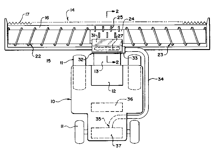
Figure 1 is a top plan view of a combine harvester
according to the present invention, with the reel omitted
for convenience of illustration.
Figure 2 is a cross sectional view along the lines
2-2 of Figure 1.
Figure 3 is an isometric view of thè dust removing
system of Figures 1 and 2.
`~ ~ 4 - 2102817
In the drawings like characters of reference
indicate corresponding parts in the different figures.
DETAILED DESCRIPTION
The combine harvester shown in Figures 1 and 2 is
generally of conventional nature and is thus shown
schematically and described hereinafter only in broad terms.
The combine harvester thus comprises a main frame generally
indicated at 10 mounted on ground wheels 11. The main frame
is self-propelled and includes a cab section generally
indicated at 12 mounted forwardly of the main frame between
the front wheels.
At the forward end of the main frame is provided a
feeder housing 13 which is arranged to receive crop material
from a header 14 for transportation upwardly and rearwardly
from the header into the main housing for crop separation in
conventional manner. The feeder housing comprises a
rectangular tubular duct with a transportation system
mounted therein (not shown) for carrying the crop material
upwardly and rearwardly into the main frame. The header is
attached to the front of the feeder housing for movement
therewith and comprises a transverse frame structure 15 to
which is attached a forwardly extending table 16. At a
front edge of the table is mounted a sickle knife 17 which
extends across the full width of the header and acts to cut
the standing crop which is then caused to fall onto the
21~2~1~
table 16. The movement of the crop is controlled by a reel
18 which rotates in the direction to sweep the material
rearwardly over the sickle knife and onto the table 16.
The crop is transported longitudinally of the
header toward the feeder housing 13 by an auger
transportation system generally indicated at 19 including a
cylinder 20 which rotates about an axis 21 in a direction
downwardly and rearwardly so as to turn the crop material
underneath the cylinder 20. On the outside surface of the
cylinder is mounted two auger flight sections 22 and 23
which are shaped and arranged so that the rotation of the
cylinder causes the crop material to be moved inwardly
toward the feeder housing 13. The auger flight sections 22
and 23 terminate at a position adjacent the feeder housing
13 at which point is provided a cylindrical drum portion 24
having a plurality of holes through which fingers 25 pass.
The fingers are mounted for rotation about an axis 26 which
is offset from the axis 21 so that the fingers project
outwardly through the holes in the drum 24 in a forward
direction but then gradually retract as the fingers move
toward the bottom and rear of the drum with the drum so as
to release the crop material to enter into the feeder
housing through an opening 27 in the frame 15. The opening
27 is rectangular and has a width and height substantially
equal to that of the feeder housing.
- 6 ~ 21028 17
The above arrangement is conventional and the crop
material is effectively carried by the auger transport
system 19 toward the feeder housing to enter into the feeder
housing for operation of the combine harvester.
Careful observation of the operation of this
arrangement by the invention has shown that the generation
of dust is effected at the center section including the
cylindrical drum portion 24. The invention therefore
provides a modification of the conventional header by the
provision of a suction shroud system generally indicated at
30.
The suction device comprises a shroud 31 mounted on
a front face of the frame member 15 together with a suction
duct 32 attached to an upper edge of the shroud 31 and a fan
33 mounted at one end of the duct 32. The fan is preferably
of the squirrel-cage type so that it is not necessary for
the material to pass over the motor and support therefor
when passing along the tube or duct 32 to the fan 33. The
material exiting from the fan 33 passes along a
transportation duct 34 which has a discharge mouth 35
located at the rear of the combine and possibly associated
with either the discharge from the chaffer sieve 36 or the
straw chopper assembly 37.
The shroud 31 includes a vertical rear wall 38
21028l7
- 7 -
extending along and in contact with the beam 15. At the
ends of the rear wall 38 are provided two sidewalls 39 which
extend forwardly from the beam 15 at right angles thereto.
A front wall 40 is inclined forwardly and downwardly from
the suction duct 32 so that the width of the sidewall 39
increases toward a lower open mouth 42. The open mouth 42
lies in a substantially plane containing the lowermost edges
of the rear wall 38, the side walls 39 and the front wall
40. The open mouth 42 terminates at a position just above
the cylindrical portion 24 of the auger transportation
system. At the mouth 42 is provided a depending skirt 43
which includes three portions connected to the sidewalls 39
and to the front wall 40 respectively. The skirt is
flexible and is fastened by rivets 44 at the lowermost edge
of the sidewalls and the front wall respectively. The lower
edge of the skirt terminates at a position closely adjacent
the upper edge of the discharge opening through the rear of
the header into the feeder housing. The flexible skirt
allows the skirt to move when impacted by the crop material.
The open mouth thus defined by the skirt is positioned just
above the cylindrical portion 24 at the opening 27 so as to
draw air and entrained material upwardly into the skirt for
passage into the tubular duct 32. Between the duct 32 and
the shrouds 31 is provided a slot 45. The dimensions of the
slot are varied so as to control the suction to remain
2102817
- 8 -
substantially constant along the length of the shroud.
In operation the crop material is cut and deposited
at the auger transportation roller and carried thereby
inwardly toward the feeder housing. Careful observation and
experimentation by the present inventor has identified that
the dust from dusty crop material is released not at the
cutting action nor the reel but only at the beating action
which is effected by the cylindrical portion 24 and the
fingers 25 as the crop material is pushed into the feeder
housing. The positioning of the shroud therefore at the
entrance to the feeder housing and above the auger system
allows the extraction of air into the shroud to carry dust
from the crop material away from the header to avoid that
dust being released into the atmosphere. This dust
collection action prevents the release of dust from
obscuring the vision of the driver positioned just above the
feeder housing or from entering the area of the driver and
causing breathing air contamination.
The device can be used either with a straight-cut
header or a pick-up type header. In an alternative
arrangement, the fan can be mounted at the rear side of the
header frame to improve visibility. The shroud also can
have a hinge at the upper edge to allow it to pivot upwardly
and rearwardly to allow better access to the area underneath
- 9- 2102817
the shroud and in front of the opening in case of a plug in
the table auger. A vent can also be provided on the front
of the tube 32 to allow dust extraction from the area of the
reel.
Since various modifications can be made in my
invention as hereinabove described, and many apparently
widely different embodiments of same made within the spirit
and scope of the claims without departing from such spirit
and scope, it is intended that all matter contained in the
accompanying specification shall be interpreted as
illustrative only and not in a limiting sense.