Note : Les descriptions sont présentées dans la langue officielle dans laquelle elles ont été soumises.
~10~
Technical Field
The present invention relates generally to apparatus and
methods for necking-in container bodies preferably in the form
of a cylindrical one-piece metal can having an open end
terminating in an outwardly directed peripheral flange merging
with a circumferentially extending neck and, more particularly,
to an improved spin flow necking process and apparatus for
controlling the final movement of forming members to prevent
unacceptable plug diameter variation.
Back~round Art
Spin flow necking is a process of necking-in an open end of
a metal container to provide a flange which allows a can end to
be seamed thereto after filling. Necking also makes conveying
of the cans easier since, with only slight flange overlap, the
cans contact body-to-body instead of flange-to-flange which would
otherwise cause tilting and conveying jams.
While numerous necking processes have been developed since
the 1970's, a particularly promising spin flow process and
apparatus having the potential of allowing can ends to be necked-
in to increasingly smaller diameters is disclosed in U.S. Patent
4,781,047, issued November 1, 1988 to Bressan, which is assigned
to Ball Corporation and is exclusively licensed to the assignee
of the present invention, Reynolds Metals Company. The
disclosure of this patent is hereby incorporated by reference
herein in its en'irety. It concerns a process where an
externally located free spinning forming roll 11 ~Figure 1) is
.. , . . .,, , . ,. . , ~
moved inward and axially against the outside wall C' of the open
end C" of a rotating trimmed can C to form a conical neck at the
open end thereof. With reference to Figure 1, a spring-loaded
holder or slide roll l9 supports the interior wall of the can C
5 and moves axially under the forming force of the free roll 11.
This is a single operation where the can rotates and the free
roll 11 rotates so that a smooth conical necked end is produced.
In practice, the can is then flanged. The term "spin flow
necking" is used in this application to refer to such processes
and apparatus, the essential difference between spin flow necking
and other types of spin necking being the axial movement of both
the external roll 11 and the internal support 19.
More specifically, the spin flow tooling assembly 10
depicted in Figure 1 (corresponding to Figure 1 of the Bressan
et al '047 patent, supra) includes a nc~cking spindle shaft 16a
rotatable about its axis of rotation A by means of a spindle gear
16 mounted to the shaft between front and rear bearings (not
shown). ~he slide roll 19 is mounted to the front end of the
necking spindle shaft 16a through a slide mechanism 28, keyed to
the shaft, which permits co-rotation of the roll 19 while
allowing it to be slid by the necking forces described more fully
below in the axially rearward direction B' away from the
eccentric ~reewheeling roll 24 located adjacent the front face
of the slide roll. The axially fixed idler roll 24, having an
axis of rotation B which is parallel to and rotatable about
spindle axis A, is mounted via bearings 16b and 23 to an
eccentrically formed front end of an eccentric roll support shaft
:: , .
-: , : ~ . ,.. i . - . . ::
.,
"., ;.: .:
i ~
18. This shaft 18 extends through the necking spindle shaft 16a.
The spindle shaft 16a is rotated hy the spindle gear 16 without
rotating the eccentric roll support shaft 18.
The outer forming roll 11 is mounted radially outwardly
adjacent the slide and eccentric rolls 19,24.
The container slide roll 19 is shaped with a conical leading
edge l9a designed to first engage the open end C~' of the
container C to support same for rotation about spindle axis A
under the driving action of the necking spindle gear 16 which may
be driven by the same drive mechanism driving each base pad
assembly 29 engaging the container bottom wall. Slide roll 19
is also free to slide axially but is resiliently biased into the
container open end C" via springs 20 which may be of the
compression typa. ;~
In operation, the container open end C" engag~s and is
rotated by the slide roll 19. The eccentric roll 24 is then
rotated into engagement with a part of the inside surface of the
container side wall C' located inwardly adjacent the open end C".
With reference to Figures 2A-2E, the external forming roll 11
then begins to move radially inward into contact with the
container side wall C' spanning the gap respectively formed
between the conical faces l9a,24e of the slide and eccentric
rolls 19,24. More specifically, the side wall C' of the spinning
container body C is initially a straight cylindrical section of
generally uniform diameter and thickness which may extend from
- 3 -
.,
, ~
,-. : ; :
.
a pre-neck (not shown) previously formed in the container side
wall such as by static die necking. As the external forming roll
11 engages the container side wall C', it commences to penetrate
the gap between the fixed internal eccentric roll 24 and the
axially movable slide roll l9, forming a truncated cone (Figure
2B). The side wall of the cone increases in length as does the
height of the cone as the external forming roll chamfer llc
continues to squeeze or press the container metal along the
complemental slope or truncated cone 24e of the eccentric roll
24 as depicted in Figure 2c. The cone continues to be generated
as the external forming roll 11 advances radially inwardly (the
slide roll 19 continues to retract axially as a result of direct
pushing contact from roll 11 through the metal) until a reduced
diameter 124 is achieved as depicted in Figures 2C and 2D. As
the cone is being formed, the necked-in portion 124 or throat of
the container C conforms to the shape of the forming portion of
the forming roll 11. The rim portions 123 of the neck which
extend radially outwardly from the necked-in portion 124 are
being formed by the complemental tapers llb,l9a of the forming
roll 11 and the slide roll 19 to complete the necked-in portion.
The ahove-described spin flow necking process, while
producing a large diameter reduction in the open end of the
container C (e~g., 0.350"), has various drawbacks when applied
to two-piece aluminum can manufacture. One drawback, for
example, is grooviny of the neck at the initial point of contact
betwean rolls 11,19 in Figure 2B which occurs on the inside of
the container as a result of the small radii on the forming roll
- 4 -
.. :~ ,: , ; ~- ,,.
:: - ~
:, ~: , . -
- . .. .: , .~
:: ; ,~. : ::,:: : ~ . . .:
.: : :-.. . : : : .,
pushing past and against the sm~ll radii on the slide roll as the
forming roll moves radially inwardly and axially rearwardly
during the necking process along the chamfer 24e of the eccentric
roll. Due to the force of spring 20 urging the slide roll 19
toward the eccentric roll 24, the metal caught between these
colliding radii (which are forcefully pressed together under
spring bias~ is grooved on both the inner and outer surfaces of
the neck. On the inside surface, this grooving results in metal
exposure (i.e., wearing away of the protective coating) which
often allows the beverage to "eat through" the container side
wall C'. It has also been discovered that such grooving often
results in actual cutting of the metal as the form roll 11 is
radially inwardly advanced from the position depicted in Figure
2B to that of Figure 2C.
As the form roll 11 moves into its radially inward most
position depicted in Figure 2B, the spring pressure acting
against the slide roll 19 in the direction of the forming roll
disadvantageously results in pinching of the end of the flange
like portion 123 and undesirable thinning of the metal. In some
cases, particularly when necking a can to smaller diameters
(eOg., 204 or 202), the edge is sometimes thinned down to a knife
edge.
To prevent both grooving of the container side wall and
excessive thinning of the flange type edge during the
aforementioned spin flow necking process, a cam ring is secured
to the slide roll to present a cam follower surface which i5
-,
,
contacted by the form roll during radial inward advancing
movement of the latter ak the on-set of the necking-in process.
The cam follower surface and the conical surface of the form roll
facing the cam follower surface are further arranged to produce
the following motions:
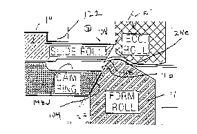
In Figure 3A, the form roll axis has moved radially inwardly
closer to the container axis and has started to form the neck.
The conical surface 24e on the eccentric roll 24 has forced the
form roll 11 toward the open end C" of the container C. The form
roll 11 has just touched the cam follower surface 104. The small
radius 106 on the form roll 11 is very close to the small radius
108 on the slide roll 19' but does not pinch the metal between
these two points. This is because the cam ring follower surface
104 is positioned so these radii 106,108 may approach each other
but stay separated by a distance slightly greater than the
initial side wall thickness. This is presently understood to be
a key feature in the elimination of metal exposure and neck
cracks caused by excessive contact pressure between the two small
radii 106,10~ in the uncontrolled collison of khe form roll 11
with the metal wrapped around the small radii 108 on the slide
roll 19 in the prior spin flow necking process described
hereinabove. In other words, since the form roll 11 contacts the
cam follower surface 104 as the two radii 106,108 approach, such
contact results in retraction or rearward axial sliding movement
of the slide roll 19' which permits the kwo radii to move past
each other.
In Figure 3B, the form roll ll has penekrated further
, . , . . . . -,
.. : ::. . . ;, .:: .
~tween the eccentric roll 24 and the slide roll 19'. The small
radius 106 on the form roll 11 is just passing the small radius
108 on the slide roll 19'. The rolls 11,19' do not pinch the
metal but have moved closer. As mentioned above, the form roll
11 is forcing the slide roll 19' back by contact between the form
roll and the cam ring 102 instead of contact at this point
between the form roll and the slide roll as occurred in the
aforesaid prior spin flow necking process.
In Figure 3C, the form roll 11 has continued its penetration
and the small radius 106 is past the small radius 108 on the
slide roll 19' (point A). At this point, the conical surfaces
l9a,11b on the slide roll and the ~orm roll, respectively, are
opposite and parallel each other. The slide roll 19' and cam
ring 102 have been pushed to the left in Figure 3C. The
combination of the metal thickening as a result of being squeezed
between the form roll 11 and the eccentric roll 24 as the metal
wraps arou.nd the forming surface lla o~E the form roll, and the
shape of the left or trailing conical surface llb on the form
roll, has reduced the relative clearance between the ~orm roll
and the slide roll so that the form roll is now actually putting
slight pressure on the metal.
In Figure 3D, the form roll 11 has now penetrated further
into the gap between the eccentric and slide rolls 24,1~'. The
form roll 11 is clearl~ clamping the metal between it and the
slide roll 19' and, as a result, a gap 130 has opened up between
the form roll surface llb and the cam ring follower surface 104.
-- 7 --
.
' " ';
' , ' ' ,. ~ ~
.
~ ~ ~ L~ ~ b ~
The form roll 11 is now pushing the slide roll 19' directly in
the axially rearward direction through its contact with the
metal, and not through the cam ring 102. Since the small radii
106,108 between the form roll 11 and slide roll 19' have already
"slipped" past each other without undesirable grooving of the
metal therebetween, the direct interaction of the form roll in
thinning and shaping the metal against the bias of the conical
surface l9a on the slide roll is important to ensure proper
necking and distri~ution of metal.
In Figure 3E, the form roll 11 has now penetrated to its
radially inward most position to complete the formation of the
spin flow neck. During the entire forming process, between 20
to 24 revolutions of the container C are required, depending on
15 the diameter, thickness and the amount of diameter reduction in
the container end. The rolling contact between the form roll 11
and the slide roll 19' has thinned the edge of the flange
slightly. There~ore, in accordance with a further feature of
this invention, the form roll 11 now once again contacts the cam
20 ring 102 to prevent further thinning of the flange area of the
container C, i.e., gap 130 has closed.
The foregoing cam ring improvement to the spin flow necking
process is disclosed in U.S. Patent Application Serial No.
25 07/929,933, filed August 14, 1992, by Harry W. Lee, Jr. et al,
which application is assigned to Reynolds Metals Company, the
assignee of the present application. The disclosure of this
application is hereby incorporated by reference herein in its
- 8 -
::: . : . , : . : :
: : ,`. ' . ` ' ' ., : '. '. : ' ' ' ' ~:
, . ':
: ' ~ . . ., .
~ .l V i
entirety.
The cam ring advantageously eliminates the grooving and cut
necks, as well as excessive thinning of the flange, that were
prevalent hefore its introduction. However, the interaction of
the outer form roll with the eccentric and slide rolls to achieve
the final necked-in state depicted in either Figure 2E (no cam
ring) or Figure 3E (with cam ring) has been discoveredl through
extensive experimentation, to directly affect the plug diameter
(i.e., the inner diameter of the necked-in portion such as
measured at 124 in Figure 2E) and the length o~ flange 123, with
or without the cam riny, and at any given base pad setting ~i.e.,
the fixed distance during necking between the base pad 29
supporting the can bottom and the axially immovable eccentric
roll), resulting in unacceptable variations therein. In a can
plant environment, particularly when employing numerous
necking~in tooling assemblies in a multi-station machine of the
type disclosed in U.S. Patent Application Serial No. 07/929,932,
filed August 14, 1992, by Harry W. Lee, Jr. et al, entitled "Spin
Flow Necking Apparatus and Method of Handling cans Therein",
assigned to Reynolds Metals ~ompany, the present assignee,
control over the plug diameter and flanqe width achieved with the
tooling assembly at each station is critical to ~chieving
homogeneity in produck and successful continuous operation. The
disclosure of the '932 application is hereby incorporated by
reference herein in its entirety.
It is accordingly an object of the present in~ention to
,
. . .; . ., : , ~ ~
:: , , ,
. . . . .
;, ; : , -:
~ V~l
prevent unacceptable variations in can plug diameter and flange
length during the spin flow necking process.
Another object is to control the interactiorl of the outer
form roll with the inner slide roll to ensure such uniformity in
plug diameters and acceptable plug diameter variation.
Yet another object is to control the aforesaid interaction
between the outer form roll and the inner slide roll with the can
by limiting the final movement of the inner slide roll and
thereby the final movement of the outer form roll so that the
final radially inward advancing movement of the lattPr is
directly controlled by controlling the movement of the inner
slide roll.
Yet another object is to provide 21 control mechanism that
may be installed in each tooling assembly in the plant tool room
so as to pre-set the movement of the inner slide roll to achieve
the aforesaid uniformity in plug diameter, prior to installing
the assemblies in a multi-station machine for continuous
production of product.
Yet another object ia to provide a plug diameter control
mechanism which is simple in design, easy to install, and capable
of rugged continuous operation without wear.
-- 10 --
, . , ~ . . .
. :' .: . :: : . . : !
Disclosure of the Invention
An apparatus for necking-in an open end of a container body
comprises a first member and a second member mounted for engaging
the open end of the container side wall along an inner surface
thereof. Means is provided for rotating the container body and
externally located means moves radially inward into deforming
contact with an outside surface of the container side wall in a
region thereof overlying an interface between the first and
second members. Such contact between the externally located
means with the side wall causes the contacted wall portion to
move radially inwardly into a gap formed at the interface,
caused by axial separation of the first and second members under
the action of the radially inward advancing movement of the
externally located means into the gap to thereby neck-in the side
wall. In accordance with the present invention, means is
provided for limiting the final axial movement of the first
member which in turn controls the ~in,al radially inward most
lo~ation of the externally located means to ensure substantially
uniform plug diameters in the necked-in cans.
In the preferred embodiment, the radial movement of the
externally located means is cam controlled and the means for
limiting its final radially inward most location overrides the
radial movement otherwise provided through the camming surface.
In the preferred embodiment, the first member is a slide
roll engaging and supporting the inside of the container open
.
, . ~. .... .. .
end. The slide roll is mounted for driven rotary motion aboutr
and axial movement along, the container axis. The slide roll is
resiliently biased into the container open end. The second
member is an axially fixed roll mounted in axially inwardly
spaced relation to the slide roll for engagement with an inside
sur~ace of the container side wall. The second roll has a
conical end surface which faces the open end of the container and
the slide roll includes a conical end surface facing the conical
end surface of the axially fixed roll in opposite inclination
thereto. The externally located means is a form roll having a
peripheral deforming nose positioned externally of the container
side wall and mounted for free rotary and controlled radial
movement towards and away from the container. The form roll is
biased for axial movement along an axis parallel to the container
axis. The form roll deforming nose includes first and second
oppositely inclined conical surfaces which are respectively
opposed to the conical surfaces on the second roll and slide
roll.
The limiting means preferably includes a StQp spacer means
which is fixedly mounted ts a tooling spindle housing supporting
the first and second rolls. The spacer means includes a stop
surface in axial alignment with a rearward facing movable annular
surface of the slide roll assembly. Without the spacer means,
the slide roll assembly is normally free to move (against
resilient bias) in the axially rearward direction towards the
spindle housing as a result of camming engagement with the cam
controlled, radially and axially movable outer form roll, without
- 12 -
: ,~.; : :: , ' , :. . :~ , , , ' , :: .
I'bottoming out" of the slide roll assembly against the spindle
housing. However, with the spacer means of the present
invention, the stop surface contacts the slide roll assembly to
prevent further axial retracting movement thereof before the cam
controlled outer form roll has otherwise completed its radially
inward movement as a result of cam follower action. Stopping of
the slide roll assembly in this unique manner prevents further
radially inward advancing movement of the outer form roll which
advantageously results in substantially uniform plug diameters
in successively necked cans.
The spacer means of the present invention is preferably usad
in combination with the cam ring improvement mounted to the slide
roll radially outwardly adjacent therefrom.
A method of spin flow necking-in an open end of the
cylindrical container body is also disclosed. The method
comprises the steps of positioning inside the container body an
axially fixed roll engagable with the inside surface of the
container body. The axially fixed roll has a sloped end surface
which faces the open end of the container body. A slide roll is
- also positioned inside the container body which fits the inside
diameter of the open end to support same. The slide roll has an
end which faces the sloped end surface of the axially fixed roll.
The slide roll is supported for axially displacement away from
the axially fixed roll. The slide roll end and the sloped end
surface of the axially fixed roll define a gap therebetween~
An outer form roll is positioned opposite the gap radially
outwardly from the container body for axial displacement away
from the axially faced roll during contact with the sloped end
of same. The form roll has a trailing end portion and a
peripheral forming portion. As the container body spins, the
form roll is advanced radially inwardly relative to the gap so
that the trailing end portion presented by the roll and the
sloped end surface of the axially fixed roll engage the container
body between them while a trailing end portion of the form roll
moves inwardly along the sloped end surface of the axially fixed
roll to roll a neck into the container body. As the body
continues to spin while the form roll moves inwardly, the slide
roll is retracted axially until the roller has spun an outwardly
extending portion on the end portion of the container body
engaged between the slide roll and the container. In accordance
with the method of the invention, the ~inal axial retracting
movement of the slide roll is controlled by having the slide roll
contact a spacer fixedly mounted axially rearwardly of the slide
roll. Such limiting contact prevents further radially inward
advancing movement of the outer form roll by overriding the cam
follow~r movement of the outer form roll. This in turn produces
substantially uniform plug diameters in th~ necked-in containers.
In accordance with a further feature of the invention, the
axial retracting movement of the slide roll, prior to contacting
~5 the spacer, is controlled by contact between a surface of the
form roll with a cam follower surface. More specifically, the
form roll has conical surfaces which are respectively engaga~le
with the sloped end surface of the axially fixed roll and another
- 14 -
sloped end surface on the slide roll. These form roll conical
surfaces are smoothly connected with a curved forming surface
extending therebetween and defined by a pair of small radii. The
sloped end of the slide roll is also smoothly connected through
another small radius to the axially extending surface thereof
which is engagable with the inside surface of the container body.
The cam follower surface operates to axially retract the slide
roll as the small radius on the form roll approaches the small
radius on the slide roll to thereby prevent pinching of the
container side wall between these two small radii by allowing the
radii to approach each other while maintaining separation
therebetween by a distance slightly greater than the original
thickness of the container side wall. Continued radially inward
forming movement past a predetermined point at which the metal
of the container side wall between the slide roll and the conical
surface of the form roll has thickened will result in the form
roll putting slight pressure directly on the metal. A gap opens
between the form roll and cam follower surface so that the form
roll is now pushing the slide roll direc~tly through contact with
the metal and not through contact with the cam follower surface.
As the outermost end of the container side wall moves between the
form roll and the slide roll, the form roll will once ~gain
contact the cam follower surface so that the rolling contact
between the ~orm roll and the slide roll does not excessively
thin the edge of the open end. As this occurs, the slide roll
will contact the spacer means and thereby be prevented from
further axial retr2cting movement. The conical interconnection
through the cam follower surface thereby prevents further
,', ''
radially inward movement of the form roll.
Still other objects and advantages of the present invention
will become readily apparent to those skilled in this art from
the following detailed description, wherein only the preferred
embodiments of the invention are shown and described, simply by
way of illustration of the best mode contemplated of carrying out
the invention. As will be realized, the invention is capable of
other and different embodiments, and its several details are
capable of modifications in various obvious respects, all without
departing from the invention. Accordingly, the drawing and
description are to be regarded as illustrative in nature, and not
as restrictive.
Brief Description of the Drawlnqs
Figure 1 is a cross-sectional view of a prior spin flow
necking process;
~0 Figures 2A-2E are enlarged, cross-sectional sequential views
depicting the spin flow necking forming sequence with the tooling
of Figure l;
Figures 3A-3E are enlarged, detailed sequential views
depicting the relative locations of the tooling components during
necking with the cam ring improvement;
Figure 4A is a cross-sectional illustration of a tooling
- 16 -
necking spindle assembly in accordance with the present
nventlon;
Figure 4B is a sectional view taken along the line 4B-4B of
Figure 4A;
Figure ~ corresponds to Figure 7 of applicant's co-pending
'932 application to depict cam controlled linkage and tool
activation assemblies for controlling radial movement of the
outer form rolls in a spin flow necking machine; and
Figures 6-13 are graphical comparative representations of
test results to illustrate plug diameter variations with and
without the present invention.
Best Mode for carryin~ Out Invention
Figures 4A and 4B are sectional view illustrations of a spin
flow necking assembly 1000 in accordance with the present
invention. Therein, the functional components are substantially
identical to the tooling components described in connection with
Figure 1, supra, and in connection with Figures 3A-3E, supra,
except as noted hereinbelow.
Furthermore, the spin flow necking assembly 1000 of Figure
4A is adapted to be used as one of plural spin flow necking
cartridges which may be mounted as known in the art to a main
neckin~ turret of a spin flow necking machine in respective
- 17 -
: . . : -. :-
., :: : , : :: :
1 8 ~ ~.
coaxial alignment with base pad assemblies mounted to a base pad
turret of such a machine. An exemplary embodiment of such a
machine is depicted in Figure lA of our aforesaid co-pending
application Serial No. 929,932 (hereinafter "the '932
application"), incorporated herein by reference. Except as noted
hereinbelow, the tooling assembly 1000 of Figure 4A functions in
a manner identical to the tooling assembly of Figure 5
(inc~rporated herein by reference) disclosed in our '932
application. Brie~ly, the eccentric roll 24 is rotated from its
eccentric solid line position depicted in Figure 4A in supporting
contact with the can open end into a radially inward clearance
position (not shown) via rotation of the pinion 108 through a
plurality of tooling activation assemblies 200 mounted to the
rear face of the tooling disc turret. Figure 5 herein
corresponds to Figure 7 (the written disclosure of which is
incorporatad by reference herein) of our co-pending '932
application. Therein, it can be seen that rotation of pinion 108
as well as radial movement of form roll or roller 11 (supported
by shaft 1010) is controllad through a series of radially
extending linkage arrangements 210 respectively interconnecting
each tooling activation assembly 200 to a cam follower 204 in
rolling contact with a cam surface 206 of a cam ring which is
stationarily mounted to a support frame supporting the tooling
disc turret. Further relevant details of Figure 5 will be
discussed hereinbelow.
As discussed above, each necking spindle assembly 1000
depicted in Figure 4A operates in the manner described supra with
- 18 -
referenc~ to Figures 3A-3E. However, in accordance with the
present invention, the necking operation described in connection
with Figure 3E is affected through the interposition of a
plurality of identical stop spacers 1025 which are bolted to the
front end of the spindle mounting assembly with bolts 1044
located radially outwardly from the path of movement of the slide
roll 19'. The spacers 1025 extend radially inwardly from mounting
screws 1044 to define a series of equispaced stop surfaces 1050
which are co-planar to each other and intersect the plane of
axial movement of the rear facing shoulder 1052 of the slide roll
19' . ' .
With the stop spacers 1025 of Figure 4A, as the form roll
11 is moved towards its radially innermost position of Figure 3E
under the action of cam follower 204 of Figure 5 which rotates
shaft 1010 through activation plate 275, the rear surface 1052
of the slide roll 19' contacts the stop surface 1050 of spacers
1025 which prevents further axial retraction of the slide roll
assembly. This in turn prevents or 9'freezes" final radial
movement of form roll 11 which would otharwise occur solely as
a result of contact between cam follower 204 with cam surface
206. In this manner, the final radial positioning of outer form
roll 11 is alway~ controlled by the contact between the slide
roll 19' with the spacers 1025 which axially "locks" the slide
roll to override final radially inward camming movement of the
outer form roll 11. Therefore, since the final radially inward
most location of forming surface ha of form roll 11 is now
controlled by the stop spacer arrangement 1025 described supra,
-- 19 --
the resulting plug diameter formed by this surface lla is
substantially uniform. Stated differently, as the form roll ll
is forced into the gap between the eccentric roll 24 and the
slide roll 19, the slide roll is forced away from the eccentric
roll as discussed in connection with FigurPs 3A-3D. When the
slide roll assembly 19 hits the stop spacers 1025, movement of
the slide roll is halted. This in turn stops further inward
radial travel of form roll ll. The eccentric roll 24 is axially
rigid so when the slide roll 19 hits the stop surface 1050, the
gap cannot get any wider. Therefore, the form roll 11 must stop.
Although it is theoretically possible to stop the movement
of the slide roll 19 in the necking tooling of the Figure 1
embodiment (no cam ring) by placement of a spacer attached to
collar 21 to contact the rear shoulder of slide roll 19', this
is very difficult in practice. This is because when the form
roll 11 forces the slide roll 19 against the stop surface 1025
in Figure 4A, the force of the form roll that is moving the slide
roll toward the stop acts through the cam ring and not through
the can flange itself which would otherwise occur without the cam
ring. The force required to actually form the can is
approximately 80-100 pounds and the override spring 279 (Figure
5) located on the side of the necking turret is pre-loaded to
about 200-250 pounds. Since the cam follower movement
transmitted through this spring 279 from cam follower 204 ~Figure
5) to the form roll 11 is a part of the mechanism which controls
radial movement of the form roll, when the slide roll stops the
form roll, it overrides this spring and the force of the form
- 20 -
.. , , .: . , . . ~ .. . .
roll therefore builds from 80-100 pounds up to 200-250 pounds.
This extra force must be supported by the cam ring on one side
of the form roll and the eccentric roll and the can neck on the
other side of the form roll. Therefore, if the cam ring is not
used, the force required to stop the form roll must come from the
slide roll face through the can flange to the form roll as in
Figure 1. This force on such a narrow can flange would be enough
to roll the flange to a thin knife edge which unacceptably causes
split flanges and uneven flange width.
The override spring 269 in the cam follower actuating
linkage depicted in Figure 5 was initially designed to perform
an override function upon latch-out of the form roll activation
plate 275 to prevent metal-to-metal contact between the form roll
11 and the holder and eccentric rolls 19,24 in the absence of can
bodies, by preventing the form roll from travelling into .its
final radial cam controlled position into contact with these
inner rolls, by allowing the spring loaded screw head 266 of the
connecting screw in Figure 5 to lift from its seated position to
the lifted position depicted in Figure 5. This override spring
269 now performs the additional function of allowing the linkage
length of the connecting linkage arrangement 210 of Figure 5 to
adjust so that the spring 269 is compressed approximately .006"
which provides bias to ensure that the form roll 11 moves to the
same radially inward most position each time to maintain a
consistent can plug diameter when the slide roll 19 contacts the
stop spacers 1025. This pre-set compression of about .006"
occurs when there is no can in the forming station. When a can
- 21 -
:::-; :. ;: .
2 1 i3 ~
is in the forming station, the spring is overridden more than the
.006" because of the can metal thickness.
By limiting the inward travel of form roll 11, it is
possible to maintain the plug diameter of the can open end within
much closer limits than would occur without the stop spacer
arrangement 1025. This is because the stop spacers 1025 limit
the travel of the slide roll 19 to a specific dimension which
produces a specific plug diameter. Once this specific dimension
of travel is known, the tooling can be pre-set in the tool room
to produce a can of specific plug diameter, by appropriate
selaction of stop spacer thickness which may be ground to a
requisite thickness. Pre-setting the necking tooling in this
manner in the tool room advantageously eliminates tedious
adjustment of each station (e.g., thirty stations~ on the spin
flow necking machine.
Furthermore, since the plug diamet:er is now controlled by
the slide roll travel, any adjustment to the base pad 29 (e.g.,
in Figure l) will mostly affect the flange width. Therefore,
this means that the flange width can now be adjusted
independently from the plug diameter by moving the base pad
towards or away from the necking tooling to control the flange
width. This greatly simplifies the operation of the spin flow
necking machine in a can plant environment.
Figure 6 is a graph depicting the variation in plug diameter
which occurs during consecutive can runs when using the necking
- 22 -
" , ;-,. ::: ;, : .
.. . .... . .
tooling of Figure 4A without the stop spacers 1025 of the present
invention. ThPrein, it can be seen that there exists
~onsiderable variation in the can plug diameter when employing
the tooling of Figure 4A without the stop spacers.
Figure 7 is a graph of plug diameter during a continuous run
of one hundred and sixty one cans, in the order of running,
utilizing the tooling assembly of Figure 4 with the stop spacer
arrangement 1025 of the instant invention. By comparison of the
test results between Figures 6 and 7, it is clear that the stop
spacer arrangement 1025 of the instant invention results in more
consistent, substantially uniform plug diameters versus that
achieved without the stop spacer arrangement.
The continuous runs depicted in Figures 6 and 7 each
occurred with a single base pad setting of approximately 3.973".
Figure 8 is a graph depicting the manner in which the plug
diameter varies utilizing different base pad settings and the
necking tooling of the Figure 4A without the stop spacer
arrangement 1025 of the instant invention. At each setting,
approximately 12 cans were fed in before the 20 numbered cans
depicted in Figure 8 were run. Without the stop spaaers 1025,
when the can is positioned closer to the tooling, i.e., the open
end of the can has slid further onto the slide roll, the flange
width is increased almost directly by the amount the can is moved
~orward. The plug diameter is al50 larger because of the higher
forces required to form the can with a wider flange. The results
depicted in Figure 8 show that the plug diameter tends to
- 23 -
, .,. -., ;. .
, , ;- ; .
lncrease by approximately 80% of the amount the can is moved
forward. For exa~ple, if the base pad is moved forward by about
.010" and a can is formed with the necking tooling of Figure 4A
without the stop spacers 1025 of the present invention, its
flange width would be about .010" wider and the plug diameter
would be about .008" larger than a can formed at the original
setting. In Figure 8, the tooling of Figure 4A (but without the
stop spacers) was set to make a can with a small flange and plug
and the base pad 29 was moved forward toward the tooling in
approximately .005" increments. At the first base pad setting
of 3.996", the cans produced had plug diameters which were
smaller than could be measured with a plug gauge. At the next
setting of 3.992", only a few cans could be measured which had
a plug diameter of about 2.125-1.126". The next setting of
3.985" produced cans within the range of measurement.
Thereafter, as the base pad setting decreased, all plug diameter~
were measurable.
From the graph of Figure 8, it can be seen that as the base
pad is moved toward the tooling, the average plug diameter
increases by about 80% of the base pad movement, i.e., without
thP stop spacer arrangement 1025 of the present invention.
Second, the variation in plug diameter within each test, i.e.,
at successively lower base pad settings, is higher than in
comparable tests using stop spacer arrangements as depicted in
Figure 9 which is a test conducted in a similar manner to thP
test of Figure ~ but with stop spacers.
- 24
, : , ... .. , , : :, ~: :: :
From a comparison of Figures 8 and 9, it is obvious that the
individual can plug diameters are more uniform within a single
group. Further, it is also obvious that the average plug
diameter is less affected by a change in base pad settings.
Figures 10-12 depict further test results in a manner
similar to that of Figure 9, i.e., utilizing stop spacers 1025
of the invention, but with different overrides of cam spring 269
or different numbers of revolutions during formin~. All of these
tests depict the same trends as the test results depicted in
Figure 9.
From the foregoing test results, the slope of the test
results in Figure 8 (no stop spacers according to the invention)
is about 38 which indicates '-h~t the plug diameter changes
approximately 80% of the base pad position change, as discussed
supra. However, the average slope of th~_ other curves in Figures
9-12 is about 16 which means that the plug diameter changes only
about 28% of the base pad position change. Thus, significant
advantages are achieved with the Figure 4A embodiment of the
invention utilizing the stop spacers 1025 in a production
environment where a multi-station (e.g., 30 station) machine is
employed and it is necessary to maintain all plug diameters
within about .015". The stop spacer arrangement 1025 of the
instant invention results in considerably improved
controllability in a large machine with multiple stations that
previously required tedious and repeated adjustment of both the
~orm roll and the base pad settings to maintain the plug diameter
- 25 ~
: .: : ~ . :
within acceptable limits.
Figure 13 is another graph depicting another run where the
flange width and plug diameter were measured on each can and the
average width and diameter were plotted against base pad
position. This shows that the plug diameter changes little while
the flange width changes directly as a function of base pad
position.
It will be readily seen by one of ordinary skill in the art
that the present invention fulfils all of the objects set forth
above. After reading the ~oregoing specification, one of
ordinary skill will be able to effect various changes,
substitutions of equivalents and various other aspects of the
invention as broadly disclosed herein. It is therefore intended
that the protection granted hereon be limited only by the
definition contained in the appended claims and equivalents
thereof.
- 26 -
, , :: , .: ; ~ . :, ., . : -::: - ;: , . . :,:, ,: :
. ~ , : ,,, . :- . , :: ,. :