Sélection de la langue

Search

Sommaire du brevet 2104265 

Énoncé de désistement de responsabilité concernant l'information provenant de tiers

Une partie des informations de ce site Web a été fournie par des sources externes. Le gouvernement du Canada n'assume aucune responsabilité concernant la précision, l'actualité ou la fiabilité des informations fournies par les sources externes. Les utilisateurs qui désirent employer cette information devraient consulter directement la source des informations. Le contenu fourni par les sources externes n'est pas assujetti aux exigences sur les langues officielles, la protection des renseignements personnels et l'accessibilité.

Disponibilité de l'Abrégé et des Revendications

L'apparition de différences dans le texte et l'image des Revendications et de l'Abrégé dépend du moment auquel le document est publié. Les textes des Revendications et de l'Abrégé sont affichés :

  • lorsque la demande peut être examinée par le public;
  • lorsque le brevet est émis (délivrance).
(12) Brevet: (11) CA 2104265
(54) Titre français: FORME DECORATIVE POUR CLOTURES A MAILLES DE CHAINE
(54) Titre anglais: DECORATIVE FORM FOR CHAIN LINK FENCES
Statut: Périmé et au-delà du délai pour l’annulation
Données bibliographiques
Abrégés

Abrégé anglais


A decorative form for a chain link fence of the type having post-supported
interwoven wires producing a matrix of wire lengths extending between wire cross-over centers.
The form is to be used with other similar forms to produce a decorative pattern over an area of
the chain link fence. The form comprises a pair of sections each having a face with
circumscribing sides and interlocking means to secure the sections together along edges of their
sides. The sections, when secured together over a cross-over center produce a hollow form
having opposed faces and sides extending therebetween. The sides of the form have slots, when
the form is so seated, located as to be seated over corresponding portions of the wire lengths
extending outwardly from that center. A plurality of such forms, when secured to a chain link
fence at predetermined locations may produce a predetermined design.

Revendications

Note : Les revendications sont présentées dans la langue officielle dans laquelle elles ont été soumises.


- 7 -
THE EMBODIMENTS OF THE INVENTION IN WHICH AN EXCLUSIVE PROPERTY
OR PRIVILEGE IS CLAIMED ARE DEFINED AS FOLLOWS:
1. A decorative form for a chain link fence of the type having post-supported
interwoven wires producing a matrix of wire lengths extending between wire cross-over centers,
the form to be used with other similar forms to produce a decorative pattern over an area of the
chain link fence, the form comprising a pair of sections, each having a face with circumscribing
sides and interlocking means to secure the sections together along edges of their sides, the
sections, when secured together over a cross-over center, producing a form with a hollow
interior and having opposed faces with sides extending therebetween, the sides of the form
having slots, when the form is so seated, located as to be seated over corresponding portions of
the wire lengths extending outwardly from that center.
2. A form according to claim 1 wherein the interlocking means are constructed and
positioned so as to be within the hollow interior of the form to minimize tampering when the
sections are secured together.
3. A form according to claim 2 wherein the securing means comprise a plurality of
lugs, each lug extending from an interior surface of one of the sections, each lug having an
extremity with a catch thereon, and a corresponding, catch receiving groove located on an inner
surface of the other of the sections, for each lug.

- 8 -
4. A form according to claim 1 wherein the sections are of similar shape and are
provided with circular faces and edges to produce, when secured together, a form having a
cylindrical appearance.
5. A form according to claim 3 wherein the sections are of similar shape and are
provided with circular faces and edges to produce, when secured together, a form having a
cylindrical appearance.
6. A form according to claim 1 wherein the sides of each section are provided with
a pair of slots positioned 180° from each other, the slots in one section being 90° offset from
the slots in the other section when the sections are in position secured together.
7. A form according to claim 5 wherein the sides of each section are provided with
a pair of slots positioned 180° from each other, the slots in one section being 90° offset from
the slots in the other section when the sections are in position secured together.
8. A system of graphic elements for a chain link fence comprising a plurality of
forms according to claim 1 to be secured to a chain link fence at predetermined locations to
produce a predetermined design.
9. A system according to claim 8 wherein the forms have circular faces.

- 9 -
10. A system according to claim 8 wherein the forms are of a plurality of colours.
11. A form according to claim 1 wherein the slots are of a depth such as to minimize
lateral movement of the forms when the sections are secured together in position over a cross-
over point on the fence.

Description

Note : Les descriptions sont présentées dans la langue officielle dans laquelle elles ont été soumises.

2104265
BACKGROUND OF THE ~VENTION
The present invention relates to a decorative form for chain link fences, and more
particularly relates to a plurality of such forms which may be secured to a chain link fence as
a system of graphic elements to produce a decorative design.
Chain link fences, of the type having post-supported interwoven wires producing
a matrix of wire lengths extending between wire cross-over centers, are frequently used for
fencing in areas for commercial, institutional (eg. schoolyards), domestic, agricultural and other
purposes. Such fences are not terribly attractive and have conventionally been "decorated"
simply by painting the wire or wires a particular colour. The wires are normally spaced
sufficiently far apart that lettering or designs painted on the fence would be unrecognizable.
Hence the fences, when painted are normally in a single colour.
In U.S. Patent No. 3,774,884 of Singer issued November 27, 1973, a square
plaque is taught which has deformable tabs at its periphery. These tabs are intended to be
wrapped around the wires of a chain link fence so the plaque or plaques cover one or more of
the mesh openings between the wires. U.S. Patent No. 4,651,975 of Howell issued March 24,
1987 describes and illustrates a system of grooved blocks of square configuration, with light wire
connectors, the blocks to be installed onto the wires of the fence by way of the grooves and
secured there by means of the wire connectors, thereby to close the openings in the mesh and
provide privacy or wind protection.
It is an object of the present invention to provide an alternative construction of
decorative form for a chain link fence which is economical to construct and simple to install.
It is a further object of one embodiment of the present invention to provide such a device which

2104265
will be difficult to tamper with, once installed on a chain link fence.
SUMl\/IARY OF THE INVENTION
In accordance with the present invention, there is provided for such a chain
link fence a decorative form, to be used with other similar forms to produce a decorative pattern
5 over an area of the chain link fence. The form comprises a pair of sections each having a face
with circumscribing sides and interlocking means to secure the sections together along edges of
their sides. The sections, when secured together over a cross-over center, produce a form
having a hollow interior and having opposed faces with sides extending therebetween. The sides
of the form have slots, when the form is so seated, located so as to be seated over corresponding
10 portions of the wire lengths extending outwardly from that center.
The form in accordance with the present invention is economical to construct and
simple to install. Where, as in a preferred embodiment of the invention, the interlocking means
are constructed and positioned so as to be within the hollow interior of the form, are difficult
to tamper with.
BRlEF DESCRIPTION OF THE DRAW~GS
These and other objects and advantages of the invention will become apparent
upon reading the following detailed description and upon referring to the drawings in which:
FIGURE 1 is a plan view of a section of chain link fence on which a plurality of
forms, in accordance with the present invention, having been installed to provide a graphic

2104265
_ -- 3
design;
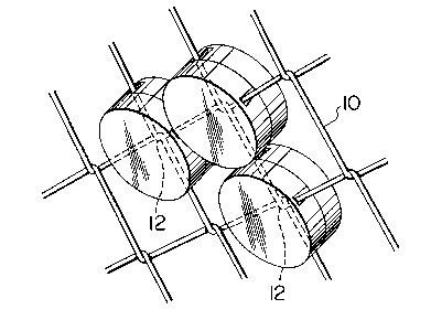
FIGURE 2 is an enlarged view in perspective of a portion of the fence of FIGURE
1, illustrating in more detail the location and positioning of the forms of the present invention
thereon; and
FIGURE 3 is an exploded perspective view of a pair of sections which produce
a form in accordance with the present invention on a chain link fence.
While the invention will be described in conjunction with an illustrated
embodiment, it will be understood that it is not intended to limit the invention to such
embodiment. On the contrary, it is intended to cover all alternatives, modifications and
equivalents as may be included within the spirit and scope of the invention as defined by the
appended claims.
DETAILED DESCRIPTION OF THE PREFERRED EMBODIMENTS
In the drawings, similar features have been given similar reference numerals.
Turning to the drawings there is illustrated in FIGURE 1, on a conventional chain
link fence 2, supported by posts 4, a design created by a plurality of forms 6 in accordance with
the present invention.
As can be seen more particularly in FIGURES 2 and 3, chain link fence 2 is
formed by wires 8 which have been interwoven, as illustrated, to produce a matrix of wire
lengths 10 extending between wire cross-over centers 12. It should be noted, particularly from
FIGURE 3, that each wire 8 "enters" and "departs" from each cross-over point 12 in a different
plane, so that, in a sense, the chain link fence, when viewed in plan from above, has a thickness

2104265
being the distance between the two planes in which the lengths 10 of each wire 8 sit.
In accordance with the present invention, a plurality of forms 6 are secured at
applop-iate cross-over points 12. Each of the forms 6 comprises a pair of sections 14, in the
illustrated embodiment of circular or disc-like configuration, having a face 16 and circumscribing
sides 18. The sections 14 are each provided with approp.iate interlocking means 19 so that they
can be secured together along confronting edges 20 of sides 18 to produce a form 6 having a
solid exterior appearance. When the sections 14 are secured together, each opposing face 16 is
seated on an opposite side of fence 2, and the hollow interior of the form 6, thus produced,
encloses a corresponding cross-over point 12 of wires 8 and portions of lengths 10.
Slots 22 are provided, at 180 opposed locations, in sides 18 of each section 14as illustrated, through which corresponding lengths 10 of wire 8 may pass when the sections are
in position on and over a cross-over point 12 on fence 2. The slots 22 of each section are,
however, offset 90 with respect to the slots of the corresponding section 14 when in position,
as will be understood from FIGURE 3, since the lengths 10 on each "side" of fence 2, at a
particular cross-over point 12 are similarly offset 90 with respect to the corresponding lengths
10, on the same wire 8, on the "other" side of the fence at that cross-over point. The depths
of slots 22 are preferably such as to minimize lateral movement of the forms when the sections
are secured together in position over a cross-over point on the fence.
As well, it will be understood from FIGURE 3 that the distance between the innersurfaces of faces 16, when sections 14 are secured together on a cross-over point 16, must be
at least as great as the "thickness" of the fence so that wires 8 will not obstruct the securing
together of sections 14 at that location.
The interlocking means l9 are preferably formed so as to be hidden from view,

2104265
when sections 14 are secured together, minimizing the ability of a person to tamper with the
form when in position. In the illustrated embodiment, interlocking means 19 comprises a
plurality of lugs 24 extending downwardly from an inner surface of sides 18, of one of the
sections 14, outwardly extending catches 26 being positioned at the extremities of lugs 24 as
5 illustrated. At corresponding, appropliate locations in the other of the sections 14 are provided
corresponding grooves 28 for catches 26. To facilitate the securing together of sections 14,
guide channels 29 are provided in the walls of section 14 adjacent grooves 28, to facilitate the
passage of the corresponding catch 26, on the other section 14, to groove 28. Lugs 24 are
provided with some resiliency, and the outer surfaces of catches 26 are bevelled so that catches
26 will ride over the edges of the other section 14 and inner surfaces of sides 18 until they
contact grooves 28, into which they will then spring in mated engagement. While this
construction of interlocking means is a preferred one, because of its ability to minimi7e
tampering, it will be understood that any other form of interlocking means, permanent or
releasable, may be provided to the sections 14, appropriate to any given function or location in
15 which the forms 6 may be used.
The sections 14 may be of any appropriate material, but are preferably of molded,
rugged plastic. They may also be of any desired colour or colours, appropriate to a desired
graphic design for fence 2.
When in position, as illustrated in FIGURE 1, a plurality of plugs provide an
20 attractive, highly visible graphic design for a fence which may significantly improve that fences
appearance. While a design has been illustrated in FIGURE 1, it is obvious that, alternatively,
a plurality of forms 6 may be assembled on a fence 2 to provide written text, for example as a
tool for corporate identification or to provide a relatively permanent, strongly visible indication

210~265
of hazards whieh might exist behind a fence. Onee in position, the seetions provided with the
interloeking means as deseribed herein are extremely difficult to remove, minimizing the ehance
for vandalism or other forms of unwanted removal. Moreover, the forms in accordance with
the present invention, when compared with previously noted prior art ehain line fenee
S attaehments, are extremely simple to eonstruet and install.
Thus it is apparent that there has been provided in aeeordanee with the invention
a deeorative form for a ehain link fence that fully satisfies the objects, aims and advantages set
forth above. While the invention has been described in conjunction with a specific embodiment
thereof, it is evident that many alternatives, modifications and variations will be apparent to
10 those skilled in the art in light of the foregoing description. Accordingly, it is intended to
embraee all sueh alternatives, modifieations and variations as fall within the spirit and broad
seope of the invention.

Dessin représentatif
Une figure unique qui représente un dessin illustrant l'invention.
États administratifs

2024-08-01 : Dans le cadre de la transition vers les Brevets de nouvelle génération (BNG), la base de données sur les brevets canadiens (BDBC) contient désormais un Historique d'événement plus détaillé, qui reproduit le Journal des événements de notre nouvelle solution interne.

Veuillez noter que les événements débutant par « Inactive : » se réfèrent à des événements qui ne sont plus utilisés dans notre nouvelle solution interne.

Pour une meilleure compréhension de l'état de la demande ou brevet qui figure sur cette page, la rubrique Mise en garde , et les descriptions de Brevet , Historique d'événement , Taxes périodiques et Historique des paiements devraient être consultées.

Historique d'événement

Description Date
Le délai pour l'annulation est expiré 2008-08-18
Lettre envoyée 2007-08-17
Inactive : CIB de MCD 2006-03-11
Inactive : TME en retard traitée 2005-08-16
Lettre envoyée 2004-08-17
Lettre envoyée 2004-03-23
Inactive : Transferts multiples 2004-03-02
Accordé par délivrance 1996-06-18
Demande publiée (accessible au public) 1995-02-18
Toutes les exigences pour l'examen - jugée conforme 1993-08-17
Exigences pour une requête d'examen - jugée conforme 1993-08-17

Historique d'abandonnement

Il n'y a pas d'historique d'abandonnement

Taxes périodiques

Le dernier paiement a été reçu le 

Avis : Si le paiement en totalité n'a pas été reçu au plus tard à la date indiquée, une taxe supplémentaire peut être imposée, soit une des taxes suivantes :

  • taxe de rétablissement ;
  • taxe pour paiement en souffrance ; ou
  • taxe additionnelle pour le renversement d'une péremption réputée.

Veuillez vous référer à la page web des taxes sur les brevets de l'OPIC pour voir tous les montants actuels des taxes.

Historique des taxes

Type de taxes Anniversaire Échéance Date payée
TM (brevet, 4e anniv.) - petite 1997-08-18 1997-08-15
TM (brevet, 5e anniv.) - petite 1998-08-17 1998-08-17
TM (brevet, 6e anniv.) - petite 1999-08-17 1999-08-13
TM (brevet, 7e anniv.) - petite 2000-08-17 2000-08-15
TM (brevet, 8e anniv.) - petite 2001-08-17 2001-08-14
TM (brevet, 9e anniv.) - petite 2002-08-19 2002-08-08
TM (brevet, 10e anniv.) - petite 2003-08-18 2003-08-11
Enregistrement d'un document 2004-03-02
TM (brevet, 11e anniv.) - petite 2004-08-17 2005-08-16
Annulation de la péremption réputée 2004-08-17 2005-08-16
TM (brevet, 12e anniv.) - petite 2005-08-17 2005-08-16
TM (brevet, 13e anniv.) - petite 2006-08-17 2006-07-05
TM (demande, 2e anniv.) - petite 02 1995-08-17
Titulaires au dossier

Les titulaires actuels et antérieures au dossier sont affichés en ordre alphabétique.

Titulaires actuels au dossier
LDMEDIA INC.
Titulaires antérieures au dossier
DAVID WATSON
Les propriétaires antérieurs qui ne figurent pas dans la liste des « Propriétaires au dossier » apparaîtront dans d'autres documents au dossier.
Documents

Pour visionner les fichiers sélectionnés, entrer le code reCAPTCHA :


Pour visualiser une image, cliquer sur un lien dans la colonne description du document. Pour télécharger l'image (les images), cliquer l'une ou plusieurs cases à cocher dans la première colonne et ensuite cliquer sur le bouton "Télécharger sélection en format PDF (archive Zip)" ou le bouton "Télécharger sélection (en un fichier PDF fusionné)".

Liste des documents de brevet publiés et non publiés sur la BDBC .

Si vous avez des difficultés à accéder au contenu, veuillez communiquer avec le Centre de services à la clientèle au 1-866-997-1936, ou envoyer un courriel au Centre de service à la clientèle de l'OPIC.


Description du
Document 
Date
(aaaa-mm-jj) 
Nombre de pages   Taille de l'image (Ko) 
Revendications 1995-04-08 3 155
Page couverture 1995-04-08 1 46
Abrégé 1995-04-08 1 53
Description 1995-04-08 6 283
Dessins 1995-04-08 2 109
Page couverture 1996-06-18 1 13
Description 1996-06-18 6 230
Revendications 1996-06-18 3 73
Abrégé 1996-06-18 1 23
Dessins 1996-06-18 2 107
Dessin représentatif 1998-02-20 1 13
Courtoisie - Certificat d'enregistrement (document(s) connexe(s)) 2004-03-23 1 105
Avis concernant la taxe de maintien 2004-10-12 1 173
Quittance d'un paiement en retard 2005-09-01 1 165
Avis concernant la taxe de maintien 2007-10-01 1 173
Avis concernant la taxe de maintien 2007-10-01 1 174
Taxes 2003-08-11 1 32
Taxes 1999-08-13 1 39
Taxes 2001-08-14 1 33
Taxes 1998-08-17 1 49
Taxes 2002-08-08 1 34
Taxes 1997-08-15 1 45
Taxes 2000-08-15 1 32
Taxes 2005-08-16 1 26
Taxes 2005-08-16 1 28
Taxes 2006-07-05 1 28
Taxes 1996-08-16 1 44
Taxes 1995-06-13 1 41
Correspondance reliée au PCT 1996-04-09 1 41
Correspondance de la poursuite 1995-02-27 2 46
Demande de l'examinateur 1995-01-12 1 51