Note : Les descriptions sont présentées dans la langue officielle dans laquelle elles ont été soumises.
-1- 2~ 0 ~ 19
SUPPORT STRUCTURE WITH WIRING
FIE;I.D OF THE; I~VENTION
THIS INVENTIO~ relates to 3upport tructur~s
whioh arl3 provlded with wiring for carrylns~ power ~nd/or
signalling to or from equlpment assoclate~d wlth the support
5 ætrua,ture.
More particularly, it relates to Bupport
.~tructures of the kind.comprising a slotted U-sect~on ahann~l
whioh defines a pas~age along the channel~ and brackets which
have teeth and are aonneated to the ahannal by ~ho testh
enterlng, through slots in the channel, into said pa~sa~e.
.
SA~ARY OF THE INVE~Q~
Aaaording ~o the invention there i9 provided a
support structure which aomprises an elongate slotted me~ber
deinlng a passage along the member and having slot~ therein
~t re~ularly spaced intervals, bracket~ which have teeth and
are connected to the member by -the teeth entexlng into the
pa~age through ths slots, and a conduator for carrylng powor
and~or signalll~g to or from electrical equipm~nt assoclated
with the support struature, the conductor running along the
pa~sage.
There may be electrical conta~t with the
conductor through a sald slot which is unocoupied by a said
,, ~ - ~ .
. - ,, , .. , ~ ., ~ . .
.
,
. . . ~ .. - . . , ~ , -
2~3~9
2- ~ :
tooth.
Ther~ may be a plug-in electrical connector
havlng a tongue which e~ters into the passage throu~h a said
slot which i~ unoccupied by a said tooth, the ton~us carrying
a tar~inal wheraby el~otrlcal con~act i8 establi~hed ~ith the
onnduoto~.
Tne alon~ate slotted member may comprise a
slotted U-section channel having two rows of slot~ therein, ~:~
the slots being arranged in lat~rally spaced palrs, in which
ev~nt the electrioal conn~ctor may have a pair of said
tong~es each entering lnto tha pas~a~ through a
corres~onding one o~ the slots of a said p~ir o 810t8.
The support str~ct~re may ~urther aomprises a
conductor support exte~dlng along the passag~, the conductor :~.
support belng of an extruded material, and the conductor
being support~d by the conductor support.
': '
. In one for~ of the invention the elongate slotted
member compr~es a pair of oppositely faclng slotted U-
section channels e~ah having two rows of slots therein and
the slots o~ each member bel~g arrang~d in laterally spaced
pairs, and a pair o~ side panel~ Joining the U-sactlon
ohannels ~o form a four-slded pa~sage with the U-sectlon
channels bsing on opposite sides o~ the passage, th~
electrical connector havi~g a pair of said ~ongues each
.'
210~3~
entering into tha pa~sagQ through a corresponding o~e of the
slot~ of a ~aid pair of ~lots.
The support structure may in this avent further
comprlse a pair of conductor support~ ex~endlng along the
pa~sage, the conductor supports eaoh beiny o~ an extruded
matarial and each carrying a sai~ conductor, a~d a
resiliently compr~ssible material between the conductor
supports and urglng the Go~ductor ~upports ln opposite
dire~tion~ towar~æ the corresponding U-section channels.
~he lnvention e~tends to a meth~d of providing a
support ~tructure wlth a conductor ~or carrying power and/or
signalling ~o o~ from equipment associated with the support
structure, which support structur~ ~ompris~s an ~longate
slotted member ~efinlng a pa~sage along th~ member and having
slots therein a~ regularly spaced intervals, and brackets
which have teeth and ~re cannected to the member by the teeth
entering into the passage through the ~lot~, the method
¢omprising insertin~ the conductor into the passaye from an
open snd oP the pa~age, and establishing ~ntact with the
~onduotor by entering a connector $nto the pas~a~e through a
said ~lot whlch is not occup~ed by a said tooth.
The invention will now be described ln more
detail, by way of example, with reference to the accompanying
drawings.
.
'
2~3~
B~X~F ~ESCRIPTION OF THE DRAWIN~S
In the drawings:
Flgure 1 is a three dimension~l view of a support
~tructure ln accordance with the invention,
~i~uras 2-and 3 are two hor~on*al section~ through the
support str~ctur~, showlng the e~fect of ~anu~acturing
tolerances;
Figuse 4 is a c~oss-section of a aonductor traak
~orming part o~ the wiring;
Figure 5 i~ an exploded three-dimensional vlew o~
various parts of ths ~uppo~t ~truat~re; and
Figure 6 i~ a horizontal section through an alternative
form of ~upport 6t~ucture in acaordance with the invention.
DE~AIl,lE;T~ DE~CRIPTION OF ~ EFERRE;D 13M~30DIM~NTS
Referrlng first to Figure 1, reference numeral 10
generally indicates a support struoturs ln the form of
ah~lv~ng o~ the kind uæed in ~upermarkets and other sel~
service ~hop~O The structure comprises a series of upright
members 12 ~only two of which are shown), each moun~ed on its
own base 14, brackets 16 connected to the upright me~bers,
8h~1VBS 18 supported on ~he brackets, and, between each pair :~ :
o~ adj~cent upright members, a series o sup~rlmposed back
panels 20. ~he back panels 20 serYe to separate the shelves
18 on one side of the structure fro~ the shelve~ on the other
sids of the structure, and also provlde lateral suppvrt ~or
2~4319 ~
the upright ~embers 12.
Elsctronic display devices ~not hown) for
providing infor~ation such a~, for e~ample, price~ of goods,
to cu~tomers ar~ mounted a}ong the edge~ o~ the ~helve~ 18.
Thes~ devices requ~re power for their operation and must also
be connac~ea to a central data proces~or for the intara~ange
of data with the data processor. Thi~ ls done by wiring
which, in accordance with the invention, includes conduator~
which run ~long pas~ages in the upright membe.rs 12, as will
0 ~9 described in more deta~l hereinafter, with xe~arence to
Ftgures 2 to 5. ~ ~eed oable (not shown) which extends down
~rom the aeil~g of th~ building in which the ~helving is
housed, enter~ into one of the upright ~embers 12 that is at
an end of the -qtructure 10, and extends down the member to
the bottom thereof. Near the bottom the feed cable le~ves
the member through an opening ln the ~ de of the memb~r and
then extends horizontally along the len~th of the structure
10. At each o~ the other upri~ht ~embers 12 a ~ranch
connection laads from th~ feed cable, and this ls connected
to oonductor traoks in that member by mean of a connector,
~n a manner that will be descrlbed in mora detail
hereinafter.
The display devices are ~onnected to the
con~uctor tracks by means of ribbon cables 24 wh.tch each have
a connector at the end thereof, in a manner that will be
descrlbed ln more detail hereinafter, wlth reference to
2'~
--6--
Figure 5.
Referri~g now to Figures 2 and 3, it wlll be sQenthat ~a~h upr:Lght member 12 co~prises a pair of slotted U-
~ect~on ohannel~ 26 arranged back-to-back and Joined by a
pair of side panels 28 with rolled ~dges ~0. The channels Z6
and the ~ide panels 28 ~o~ether ~e~ine a passage 32 whlch
extend~ ~long the ohannels.
~ he sIda pansls 28 are welded to tha channel~ 26.
A~ the jigging that is used when welding these componen-ts
0 togetheT i8 not always ~ery accura~e, the distance between
th~ cbannels Z6 i8 ~ot con~istently the same, as will becom~
evident when Figure 3 is co~pared wlth Figur~ 2. The
di~tanc~ betwesn the side ~onels 2a, howev~r, does not vary
~igni~icantly. On th~ outside o~ each o~ ~h~ side panels 28
~here is an angl~ section element which has a fold~d ba~k lip
34, wher~by the back panels 20 can be engaged with the
upr~yht member.
Extending along th~ passa~e 32 of each of the
upri~h~ m~mbers 12 e~cept the one ~hrough which the feed
cable pas~es, thcre are two conductor ~upports or tracks 36
arranged back-to-back. One or ~ore s~rips of polyurethane ~:-
~oam 38 are placed betw~en the conductor tracks~ These
strlps urge the ~onduator traoks away from one another
aga~nst the rear face~ of the ahannels 26, and ~erve to ~ :
a~commodate dif~rences in the spacing b~tween the channels.
. ~ : . . .
:; . :.. . . , . : , ;
':
,
2~3~9
As can best be s~en in Figure 4, each of the conductor tracks
36 comprises a first portion 38.1 whiah, when the conductor
track is ln position in the passage ~2, lies agains~ a
corresponding one o~ tha side panel~ 28, a ~acond portion
38.2 whlch e~tends ~t ri~ht angles to the side plate 28, and
a third portion 38.3 which ext~nds at right angls to the
second portlon 38.'2. ThP portio~s 38.1, 3B.2, and 38~3 are
conveniently constitut~d by a plastias ex~ruslon.
Alternatlvely the portlonY may be constltuted by ~n alu~inium
~,xtrusion, in which ~vent the extrusio~ may be hard anodised
so that th~ ~nodi~ing can provide the necessary insulati3n.
Alternatively, where the portions are constituted by an
aluminium extruslon, thin str~ps o~.plastics ~aterial may be
lnserted between the conductors and the aluminium so as to
lS in3ula~e ~he conduators ~rom the alumini~m.
~ he fi~st portlon 3~ provid~d with a pair of
narrow ridge~ 40 which are easlly deformed, and provided to
compen~ate or any ~ariatlons in the ~istance between the
slde panels 2a.
In the second portion 38.2 ther~ are a pair of
channels, each of which accom~odates a conduc,tor 42 which
extends along the length of the conduc~or ~rack. Likewise" ~`
the third portion 38.3 i5 provided with a pair o~ ahannels,
each o~ whlch acao~modates a conduc~or 42 ~hat extend~ along
~5 ths length of the conductor track.
.
.
' : ~ , .. ~' . ' .; .. . :
3 ~ 9
--8--
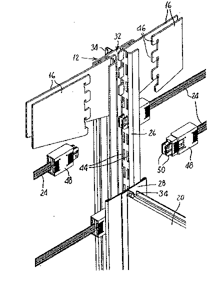
Referring now to Figure 5, it will be seen that
each of the channels 26 has two rows of sl~ts 44 therein. ~.
The brack~ts 16 hav~ t~e~h 46 whlch can ~nter via the slots
44 into the passage 32, to connect the brack~t sscurely to
thQ channel 26. ~he ~rrangement of the conductor track8 36
is such that they do not lnter~ere with en-try of th~ teeth 46
nto ths pass~ge 32.
The coNnectors referr~d ~o earlier ar~ indiaated
in Pigure 5 by re~erence numeral 48. Each of them ha~ a pair
o~ r~ctangular tongu0~ 50 whose ~ize and spacing i3 ~uch that
th~y c~n enter through ~n adJacent pair of the slots 44 into
the passage 32. The ton~ue~ 50 carry ~erminal~ whereby
electrical ~ontact can be ~stAbli~hed wlth the conductors 42.
~he branch co~nections referraa to earlier, and al80 the
ribbon c~bles 24 are connected to the conductor tracks 36 by
means o~ ~uCh connectors 48. ~he connector~ whereby the
branch connection~ are connected to ~he conductor tracks may
be ~used connectors. : ~
The conductor tracks 36 are installea by ~:
inserting them from the top end into the passage 32 and
slldgng them, wi~h the ~trip or strip~ 38 therebetween, down
~long the passage until they ara in posi~ion. A major
advanta~e of this procedure is that the wiring aan be
in~talled wlthout requiring unpacking o~ the sh~lv~s 18, and .
without the n~ed for installing cable trunking to protect the
wiring from dama~e by goods packed on the shelves or by belng
~: - . ,. , i . .
. : - - . : : : .
,
- :::.
"
- : :. .: :
%~3~9
pinched between the shelves and the ~ack pan~l~ 20 or uprigh~
members 12. The cond~ctor tracks are well protected inside
th~ upright m~mb~ri 12~
It will be noted that the conductor~ 42 on the
portion ~8~3 are relatively clos~ to th~ channels 26. Th1s
will ensure that the teeth 46 do not c~e into contact with
~h~ cvnductors should the brackets 16 be swung fro~ side to
slde.
Re~erring now to Flgure 6, there is shown a
~upport structure 60 which comprises a slotted U-~ection
ohannel 62 wh1ch is secured ~o a wall by means of a ~arew 64.
The channel 62 is of ths same type as ~he channels 26 ~f the
Figure~ 1 to 5 embodiment, having two rows o~ ~lot~ 66
therein. ~racket~ ~not shown) similar to tha brackets 16
sihown ln Figure~ 1 and 5 engage with ~he channel 62. The
ch~nnel 62 defines a pass~g~ 68, along ~hich there extends a
conductor ~rack 70 compr$~ing an extru~ion havlng channel~ in
which conductors 72 are laid. In the conductor track there
1~3 an opening 74 for receiving the ~3arew 54. Cont~ct with
the conducto~s 72 is e~tablished by means of a connector ~not
3hown~ similar to the connectors 48 of the Figures 1 ~o 5
e~ribodimsnt.
The wiring of the support structure lllustrated
in Figure 6 may, for example, be used to provide low voltage
power to 3pot light~ ~ount~d on the U-section channel.
: .: : . . ; .