Sélection de la langue

Search

Sommaire du brevet 2104357 

Énoncé de désistement de responsabilité concernant l'information provenant de tiers

Une partie des informations de ce site Web a été fournie par des sources externes. Le gouvernement du Canada n'assume aucune responsabilité concernant la précision, l'actualité ou la fiabilité des informations fournies par les sources externes. Les utilisateurs qui désirent employer cette information devraient consulter directement la source des informations. Le contenu fourni par les sources externes n'est pas assujetti aux exigences sur les langues officielles, la protection des renseignements personnels et l'accessibilité.

Disponibilité de l'Abrégé et des Revendications

L'apparition de différences dans le texte et l'image des Revendications et de l'Abrégé dépend du moment auquel le document est publié. Les textes des Revendications et de l'Abrégé sont affichés :

  • lorsque la demande peut être examinée par le public;
  • lorsque le brevet est émis (délivrance).
(12) Brevet: (11) CA 2104357
(54) Titre français: BARIL DE PLASTIQUE MUNI D'UNE TRAPPE DE VIDAGE ET METHODE DE FABRICATION CONNEXE
(54) Titre anglais: PLASTIC DRUM WITH DRAIN SUMP AND METHOD OF MAKING THE SAME
Statut: Périmé et au-delà du délai pour l’annulation
Données bibliographiques
(51) Classification internationale des brevets (CIB):
  • B65D 47/00 (2006.01)
  • B65D 01/20 (2006.01)
(72) Inventeurs :
  • GAY, RAYMOND W. (Etats-Unis d'Amérique)
(73) Titulaires :
  • GREIF BROS. CORPORATION
(71) Demandeurs :
  • GREIF BROS. CORPORATION (Etats-Unis d'Amérique)
(74) Agent: SMART & BIGGAR LP
(74) Co-agent:
(45) Délivré: 1999-04-20
(22) Date de dépôt: 1993-08-18
(41) Mise à la disponibilité du public: 1994-07-27
Requête d'examen: 1993-08-18
Licence disponible: S.O.
Cédé au domaine public: S.O.
(25) Langue des documents déposés: Anglais

Traité de coopération en matière de brevets (PCT): Non

(30) Données de priorité de la demande:
Numéro de la demande Pays / territoire Date
009,550 (Etats-Unis d'Amérique) 1993-01-26

Abrégés

Abrégé français

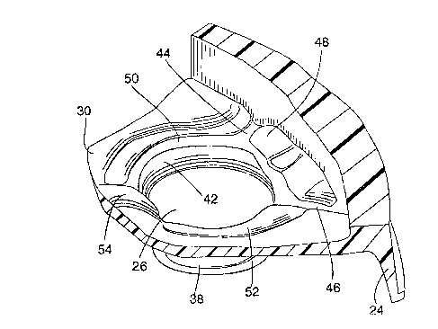
Cette invention concerne un fût monpièce en plastique ayant un dessus, un fond et une paroi essentiellement cylindrique. Le dessus est profilé du côté intérieur en forme de cuvette autour de du trou de remplissage pour que, fût renversé, tout le contenu liquide puisse s'échapper de celui-ci.


Abrégé anglais


ABSTRACT OF THE INVENTION
A one-piece plastic drum is formed with a top,
bottom and sidewall. The top is profiled to form a
sump around an access opening so that when the drum
is turned upside down, all the liquids are dispensed
from the drum.

Revendications

Note : Les revendications sont présentées dans la langue officielle dans laquelle elles ont été soumises.


-7-
WHAT IS CLAIMED IS:
1. A blow molded one-piece plastic drum capable of having all liquids contained therein
to be removed out therefrom when the drum is turned upside down comprising:
a top, a bottom and a tubular integral sidewall cooperating to form a unitary drum
body; and
a mouth extending downwardly from the top when the drum is in an upside down
position and defining a first access opening formed in said top; said top having an inner
surface pitched downwardly towards said first access opening when the drum is in an upside
down position, a ring profiled about said first access opening and interposed between the top
and mouth, at least one channel formed in the top and extending below the top inner surface
and extending from the sidewall into the ring when the drum is in an upside down position to
form a first tiered sump, at least one arcuate zone between the ring and mouth and beneath the
ring when the drum is in an upside down position to form a second tiered sump, the sumps
being arranged and constructed to collect liquid from said drum and dispense said liquid from
said drum through said first access opening when said drum is turned upside down to remove
all the liquid from the drum, whereby as the drum empties, drops of the liquid run down the
inside of the sidewall and top and because of the pitched inner surface of the top, they are
collected into the channel and arcuate zone and flow out of the access opening and in this
manner, and because the drum has no crevices or holes in which the fluid can remain as the
drum is in its upside down position, all the liquid can be safely and economically removed
from the drum and the drum can then be returned for reuse or melted down and recycled.

-8-
2. The drum of claim 1 wherein said first tiered sump includes a pair of said channel
separated by a ramp and the second tiered sump include a pair of said arcuate zones disposed
below said channel to receive liquid collected in said channel and direct the liquid to the
access opening.
3. The drum of claim 1 further comprising a second access opening having said first
tiered and second tiered sumps.
4. The drum of claim 3 wherein said access openings are disposed at a preselected
distance from the longitudinal axis of said drum.
5. The drum of claim 4 wherein the inner surface of the top is pitched downwardly
toward both of the access opening when the drum is in an upside down position.
6. The drum of claim 5 wherein a spine is formed in the top between the access openings
for reinforcing.
7. The drum of claim 1, wherein the mouth is provided with internal threads and an
externally threaded closure cap closes the access opening.
8. The drum of claim 1, wherein a chime extends upwardly from and circumferentially
around the top beyond the mouth for permitting the handling of the drum by mechanical
means.

Description

Note : Les descriptions sont présentées dans la langue officielle dans laquelle elles ont été soumises.


~ CA 021043~7 1998-04-16
TITLE OF THE INVENTION
PLASTIC DRUM WITH DRAIN SUMP
BACKGROUND OF THE INVENTION
A. Field of Invention
This invention relates to a unitary plastic drum for shipping and storing various
m~tt~.ri~l~, and more specifically to a plastic drum for liquid materials, which drum has a
sloping top with a sump formed about the drum open holes so that all the liquid can be
removed out efficiently.
B. Description of the Prior Art
Plastic drums are used frequently to ship and store various m~teri~lc These types of
drums are preferred over metal drums because they are simpler and cheaper to make, easier to
handle, and weigh less. Frequently, plastic drums are used to ship liquid m~t~.ri~l.c used in
agriculture, or the chemical industry which are highly concentrated and therefore, must be
diluted. Since these liquids are very expensive, it is important that all the contents of the
drum be removed before the drum is discarded or returned, to elimin~te waste. Frequently, a
plastic drum is emptied by turning it upside down. However, until now plastic drums were
shaped so that it was impossible to empty their contents 100%.

CA 021043~7 1998-04-16
Hence, there is a great need in the art for a plastic drum which could be emptied
efficiently or by turning it upside down.
OBJECTIVES AND SUMMARY OF THE INVENTION
In view of the above-mentioned disadvantages of the prior art, it is an objective of the
present invention to provide a plastic drum which can be efficiently emptied by turning it
over.
Yet a further objective is to provide a plastic drum which can be made efficiently and
economically for example by blow molding.
Another objective of the invention is to provide a drum which can be emptied
efficiently using standard equipment.
Other objectives and advantages ofthe invention shall become apparent from the
following description of the invention. Briefly, a plastic drum constructed in accordance with
this invention consists of a subst~nti~lly cylindrical plastic body having a straight cylindrical
side, a tope and a bottom. At least one access hole is provided on the top for filling and
emptying the drum. The top is profiled or contoured to form a sump which is concentrically
disposed around the access hole whereby as the drum is turned over, all the liquid collects in
the sump and then it runs out through the access hole. The drum is originally formed with a
top and a bottom chime for protection as well as to insure that the drum stands upright or
vertical when resting on a horizontal surface, and ease of h~n(lling.
Accordingly, the invention comprises a blow molded one-piece plastic drum capable
of having all liquids contained therein to be removed out therefrom when the drum is turned

CA 021043~7 1998-04-16
upside down comprising a top, a bottom and a tubular integral sidewall cooperating to form a
unitary drum body; and a mouth extending dowllwaldly from the top when the drum is in an
upside down position and defining a first access opening formed in said top; said top having
an inner surface pitched downwardly towards said first access opening when the drum is in an
5 upside down position, a ring profiled about said first access opening and interposed between
the top and mouth, at least one channel formed in the top and extending below the top inner
surface and extending from the sidewall into the ring when the drum is in an upside down
position to form a first tiered sump, at least one arcuate zone between the ring and mouth and
beneath the ring when the drum is in an upside down position to form a second tiered sump,
10 the sumps being arranged and constructed to collect liquid from said drum and dispense said
liquid from said drum through said first access opening when said drum is turned upside
down to remove all the liquid from the drum, whereby as the drum empties, drops of the
liquid run down the inside of the sidewall and top and because of the pitched inner surface of
the top, they are collected into the channel and arcuate zone and flow out of the access
15 opening and in this manner, and because the drum has no crevices or holes in which the fluid
can remain as the drum is in its upside down position, all the liquid can be safely and
economically removed from the drum and the drum can then be returned for reuse or melted
down and recycled.
BRIEF DESCRIPTION OF THE DRAWINGS
FIG. 1 shows an elevational view of a drum constructed in accordance with this
invention;

CA 021043~7 1998-04-16
FIG. 2 with a closure caps applied shows a top view of the drum with closure caps
removed;
FIG. 3 shows a partial cross sectional view of the drum turned upside down takenalong lines 3-3 in FIG. 2; and
FIG. 4 shows a partial section orthogonal view of one of the openings for inside the
drum.
DETAILED DESCRIPTION OF THE INVENTION
Referring now to the drawings, a drum 10 constructed in accordance with this
invention consists of a top 12, a bottom 14 and a substantially cylindrical sidewall 16.
Sidewall 16 is formed with two rings 18, 20 provided substantially equidistant from the top
12 and bottom 14 resl)e~ /ely to allow the drum to be rolled on the ground and to reinforce
the sidewall 16. At the top 12, the drum 10 is provided with a narrow neck 22 and a chime 24
which permits the h~n(lling of the drum by mechanical means such as a parrot-beak, or
forklift h~nclling
As seen more clearly in FIG. 2, top 12 is provided with two access holes 26, 28
disposed at a predetermined distance from the longitudinal axis of the drum. The structure of
the top surrounding these holes is substantially identical. Except as described below, inner
surface 30 of the top 12 is relatively smooth and is pitched toward one of the openings 16, or
18. Starting from chime 24 two raised portions 32, 34 extend toward and join a raised ring
36. A cylindrical relatively thin wall 38 rises straight up from the ring 36 to form a mouth for
the drum. The wall 38 has a radial ledge 40 which forms the top of threads 42 (seen in FIG. 3

CA 021043~7 1998-04-16
and 4) disposed helically around the inside of wall 38.
As seen more clearly in FIG. 4, when the drum is turned upside down, portions 32, 34
form on the inside surface of the top 12 two corresponding channels 44, 46 separated by a
ramp 48. Moreover, the inner surface of the top is profiled under ring 36 with two arcuate
zones 50, 52 disposed below the level of the charmels and forming with channels 44, 46 a
two-tiered surnp for the drum.
Finally a spine 54 is provided on the inner surface 30 between the two openings for
reinforcement.
The drum constructed as described above is used as follows; The drum is placed in the
upright position shown in FIG. 1, and is filled with a liquid material such as a herbicide or a
pesticide through one of the openings, such as 16. The other opening, 18, is left open for
venting. After the drum 10 has been filled, both opening are closed by standard caps 43
which may be secured to the respective opening by eng~ging int~rn~l threads 42.
In order to dispense the liquid from the drum, its caps 43 are removed and the drum is
turned upside down to allow the liquid to flow out through either or both openings 26, 28.
Importantly, as the drum empties, drops of the fluid run down inside sidewall 16 and because
of the profiled top surface 30, they are collected into the sumps formed therein by the
channels 44, 46 and arcuate zones 50, 52 and flow out of the openings. In this manner, and
because the drum has no crevices or holes in which the fluid can remain as the drum is in its
upside down position, all the fluid can be safetly and economically removed from the drum.
The drum can then be returned for reuse as is, or can be melted down and recycled.

CA 021043S7 1998-04-16
Preferably the drum is a one piece drum made for example by blow molding.
Obviously, numerous modifications may be made to this invention without departing
from its scope as defined in the appended claims.

Dessin représentatif
Une figure unique qui représente un dessin illustrant l'invention.
États administratifs

2024-08-01 : Dans le cadre de la transition vers les Brevets de nouvelle génération (BNG), la base de données sur les brevets canadiens (BDBC) contient désormais un Historique d'événement plus détaillé, qui reproduit le Journal des événements de notre nouvelle solution interne.

Veuillez noter que les événements débutant par « Inactive : » se réfèrent à des événements qui ne sont plus utilisés dans notre nouvelle solution interne.

Pour une meilleure compréhension de l'état de la demande ou brevet qui figure sur cette page, la rubrique Mise en garde , et les descriptions de Brevet , Historique d'événement , Taxes périodiques et Historique des paiements devraient être consultées.

Historique d'événement

Description Date
Inactive : CIB de MCD 2006-03-11
Le délai pour l'annulation est expiré 2003-08-18
Lettre envoyée 2002-08-19
Accordé par délivrance 1999-04-20
Inactive : Taxe finale reçue 1999-01-11
Préoctroi 1999-01-11
Un avis d'acceptation est envoyé 1998-07-24
Lettre envoyée 1998-07-24
Un avis d'acceptation est envoyé 1998-07-24
Inactive : Approuvée aux fins d'acceptation (AFA) 1998-07-06
Inactive : Supprimer l'abandon 1998-06-19
Inactive : Abandon. - Aucune rép dem par.30(2) Règles 1998-04-16
Modification reçue - modification volontaire 1998-04-16
Inactive : Dem. de l'examinateur par.30(2) Règles 1997-10-16
Inactive : Renseign. sur l'état - Complets dès date d'ent. journ. 1997-07-14
Inactive : Dem. traitée sur TS dès date d'ent. journal 1997-07-14
Demande publiée (accessible au public) 1994-07-27
Exigences pour une requête d'examen - jugée conforme 1993-08-18
Toutes les exigences pour l'examen - jugée conforme 1993-08-18

Historique d'abandonnement

Il n'y a pas d'historique d'abandonnement

Taxes périodiques

Le dernier paiement a été reçu le 1998-08-18

Avis : Si le paiement en totalité n'a pas été reçu au plus tard à la date indiquée, une taxe supplémentaire peut être imposée, soit une des taxes suivantes :

  • taxe de rétablissement ;
  • taxe pour paiement en souffrance ; ou
  • taxe additionnelle pour le renversement d'une péremption réputée.

Les taxes sur les brevets sont ajustées au 1er janvier de chaque année. Les montants ci-dessus sont les montants actuels s'ils sont reçus au plus tard le 31 décembre de l'année en cours.
Veuillez vous référer à la page web des taxes sur les brevets de l'OPIC pour voir tous les montants actuels des taxes.

Historique des taxes

Type de taxes Anniversaire Échéance Date payée
Requête d'examen - générale 1993-08-18
TM (demande, 4e anniv.) - générale 04 1997-08-18 1997-08-15
TM (demande, 5e anniv.) - générale 05 1998-08-18 1998-08-18
Taxe finale - générale 1999-01-11
TM (brevet, 6e anniv.) - générale 1999-08-18 1999-08-16
TM (brevet, 7e anniv.) - générale 2000-08-18 2000-08-18
TM (brevet, 8e anniv.) - générale 2001-08-20 2001-07-20
Titulaires au dossier

Les titulaires actuels et antérieures au dossier sont affichés en ordre alphabétique.

Titulaires actuels au dossier
GREIF BROS. CORPORATION
Titulaires antérieures au dossier
RAYMOND W. GAY
Les propriétaires antérieurs qui ne figurent pas dans la liste des « Propriétaires au dossier » apparaîtront dans d'autres documents au dossier.
Documents

Pour visionner les fichiers sélectionnés, entrer le code reCAPTCHA :


Pour visualiser une image, cliquer sur un lien dans la colonne description du document. Pour télécharger l'image (les images), cliquer l'une ou plusieurs cases à cocher dans la première colonne et ensuite cliquer sur le bouton "Télécharger sélection en format PDF (archive Zip)" ou le bouton "Télécharger sélection (en un fichier PDF fusionné)".

Liste des documents de brevet publiés et non publiés sur la BDBC .

Si vous avez des difficultés à accéder au contenu, veuillez communiquer avec le Centre de services à la clientèle au 1-866-997-1936, ou envoyer un courriel au Centre de service à la clientèle de l'OPIC.


Description du
Document 
Date
(aaaa-mm-jj) 
Nombre de pages   Taille de l'image (Ko) 
Dessin représentatif 1999-04-12 1 21
Description 1995-04-07 4 257
Dessins 1995-04-07 2 103
Revendications 1995-04-07 4 209
Abrégé 1995-04-07 1 31
Description 1998-04-15 6 186
Revendications 1998-04-15 2 67
Avis du commissaire - Demande jugée acceptable 1998-07-23 1 166
Avis concernant la taxe de maintien 2002-09-15 1 177
Correspondance 1999-01-10 1 43
Taxes 1999-08-15 1 39
Taxes 2000-08-17 1 32
Taxes 1997-08-14 1 44
Taxes 1998-08-17 1 46
Taxes 1995-08-17 1 38
Taxes 1996-07-15 1 42