Sélection de la langue

Search

Sommaire du brevet 2105226 

Énoncé de désistement de responsabilité concernant l'information provenant de tiers

Une partie des informations de ce site Web a été fournie par des sources externes. Le gouvernement du Canada n'assume aucune responsabilité concernant la précision, l'actualité ou la fiabilité des informations fournies par les sources externes. Les utilisateurs qui désirent employer cette information devraient consulter directement la source des informations. Le contenu fourni par les sources externes n'est pas assujetti aux exigences sur les langues officielles, la protection des renseignements personnels et l'accessibilité.

Disponibilité de l'Abrégé et des Revendications

L'apparition de différences dans le texte et l'image des Revendications et de l'Abrégé dépend du moment auquel le document est publié. Les textes des Revendications et de l'Abrégé sont affichés :

  • lorsque la demande peut être examinée par le public;
  • lorsque le brevet est émis (délivrance).
(12) Brevet: (11) CA 2105226
(54) Titre français: METHODE ET DISPOSITIF POUR LA DETECTION DE MARQUEURS MAGNETIQUES POUR LE SUIVI D'ARTICLES ELECTRONIQUES
(54) Titre anglais: APPARATUS AND METHOD FOR DETECTING MAGNETIC ELECTRONIC ARTICLE SURVEILLANCE MARKERS
Statut: Périmé et au-delà du délai pour l’annulation
Données bibliographiques
(51) Classification internationale des brevets (CIB):
  • G08B 13/24 (2006.01)
(72) Inventeurs :
  • CORDERY, ROBERT A. (Etats-Unis d'Amérique)
(73) Titulaires :
  • PITNEY BOWES INC.
(71) Demandeurs :
  • PITNEY BOWES INC. (Etats-Unis d'Amérique)
(74) Agent: MACRAE & CO.
(74) Co-agent:
(45) Délivré: 2001-08-07
(22) Date de dépôt: 1993-08-31
(41) Mise à la disponibilité du public: 1994-03-04
Requête d'examen: 2000-08-10
Licence disponible: S.O.
Cédé au domaine public: S.O.
(25) Langue des documents déposés: Anglais

Traité de coopération en matière de brevets (PCT): Non

(30) Données de priorité de la demande:
Numéro de la demande Pays / territoire Date
940,275 (Etats-Unis d'Amérique) 1992-09-03

Abrégés

Abrégé anglais


Method and apparatus for detecting the presence of a
magnetic marker in a dual frequency interrogation zone. A
dual frequency field is generated to produce an
interrogation zone wherein the higher frequency is
substantially higher than the lower frequency. The signal
generated by the magnetic marker is detected filtered and
amplified. Time windows are selected at the expected pulse
locations of the signal. The signals detected at the time
windows are multiplied by a window function. The product
resulting therefrom is averaged to produce a demodulated
signal and the presence of a marker in the interrogation
zone is determined by detecting the demodulated signal at
the lower frequency of the dual frequency interrogation
zone.

Revendications

Note : Les revendications sont présentées dans la langue officielle dans laquelle elles ont été soumises.


-6-
THE EMBODIMENTS OF THE INVENTION IN WHICH AN EXCLUSIVE PROPERTY
OR PRIVILEGE IS CLAIMED AIRE DEFINED AS FOLLOWS:
1. A method for detecting the presence of a soft ferromagnetic marker in a
dual
frequency interrogation zone, the steps comprising:
receiving a signal from the interrogation zone,
filtering the signal to remove noise, and limit the signal bandwidth,
amplifying the filtered signal,
deriving a window function based upon the derivative of the filtered signal,
and
selecting time windows at the expected pulse locations of the signal,
multiplying the
filtered/amplified signal at the selected time windows by the window function,
averaging the product of the filtered/amplified signal times the window
function over
each time window to produce a demodulated signal, and
determining the presence of a marker in the interrogation zone by detecting
the
demodulated signal at the lower frequency of the dual frequency interrogation
zone.
2. The method of claim 1 further including the further step of adjusting the
position of
the time windows to compensate for the earth's magnetic field.
3. The method of claim 1 further including the steps of generating a second
window
function that is 90° out of phase with the first window function and
multiplying the filtered
amplified signal by both window functions individually to produce two signals.
4. A system for detecting the presence of a soft ferromagnetic marker in a
dual
frequency interrogation zone, comprising:
at least one generating coil for generating a dual frequency field having a
high
frequency signal and a low frequency signal, in an interrogation zone,
a detection coil for detecting signals emitted by a marker located within the
interrogation zone

-7-
a band pass filter in communication with the detection
coil for filtering noise from the marker signal,
an amplifier in communication with the band pass filter
for amplifying the filtered signal,
a window multiplier in communication with the amplifier
for multiplying the amplified signal by a window function,
and
a signal generating device to generate a demodulated
signal at the lower frequency of the dual frequency field.

Description

Note : Les descriptions sont présentées dans la langue officielle dans laquelle elles ont été soumises.

C-429
2105226
APPARATUS AND METHOD FOR DETECTING MAGNETIC ELECTRONIC
ARTIChE SURVEILLANCE MARKERS
Backg~round of the Invention
Field of the Invention
In electronic article surveillance (EAS) systems, articles
being protected are tagged with a tag containing an
electronically detectable device which is referred to as a
marker. Typically, a sweep frequency interrogation
transmitter whose fregluency is swept through a resident
frequency of the tag includes a transmitting antenna located
near an exit of a protected area. A receiving antenna is
located near the transmitting antenna and forms a
passage-way with the transmitting antenna through which
someone exiting the protecting area must pass. The
receiving antenna is coupled to a receiver that detects the
signal radiated by they marker whenever the transmitter
frequency passes through the resident frequency of the
marker. There are two types of EAS systems of primary use
commercially. Radio frequency (RF) systems and magnet
systems. The instant invention has particular use in a
magnetic EAS system wherein a magnetic field is generated at
a fixed frequency. A signal is generated when the magnetic
field causes the magnEatization of a marker to switch. This
occurs near zero field amplitude.
Description of the Related Art
Although there are many EAS systems that work
satisfactorily well, all these systems face the problem of
distinguishing a. signal emitted from the EAS marker from
background noise:. For example, in U.S. Pat. No. 5,023,598,
detection is achieved by the use of averaging techniques of
a plurality of :weeps wherein peaks above a defined level
are stored in a persistent table. A symmetry test is made
on the peaky and if the peaks are persistent and
symmetrical, the presence of a marker is indicated.
Although this system works well, it is primarily directed to
radio frequency systems that detect the presence of a

2105226
--2-
resonalattank circuit. U.S. Pat. No. 5,005,001 describes an EAS system that
has a signal
generator for generating a magnetic field which includes an arrangement for
generating a
non-rotating field at a first frequency and a rotating field at a second
frequency that is lower
than the first frequency. rClhis system is designed for the purpose of
detecting magnetic
markers and represents are advancement in the constant attempt to eliminate
background
noise; nevertheless, it would be advantageous to reach a higher level of
efficiency for
detecting magnetic: markers.
SUM1VIARY OF THE INVENTION
The instant invention provides a system and method for detecting the presence
of a
ferromagnetic marker in an interrogation zone. The system includes first and
second
generating means for generating first and second magnetic fields,
respectively, at first and
second frequencies. The second firequency is substantially lower than the
first frequency.
Such a system and method is shovm and described in U.S. Patent No. 4,710,752.
In order to
enhance the detection of a magnetic marker in the field and reduce the number
of false
readings, a window demodulation scheme is used. This is achieved by selecting
time
windows at the expected pulse location of the marker, multiplying the received
signal by a
window function multiplier and averaging the product thereof over each time
window to
produce a demodulated signal. If the demodulated signal is detectable at the
second
frequency of the dual frequency field, this indicates the presence of a
magnetic marker in the
interrogation zone:.
BRIEF DESCRIPTION OF THE DRAWING
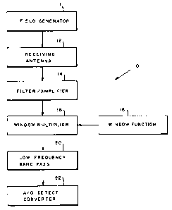
FIG. 1 is a block diagram ;showing the components of the system used for
carrying
out the invention;
FIG. 2 is a. graph showing the signal emitted at the antenna in response to
detecting a
magnetic marker;
FIG. 3 is a graph of the signal of FIG. 2 after being filtered;
v ~'' FIG 4 is a graph of the window multiplier function; and

__ 3 __ 2105226
FIG 5 is a graph of the product of the signal times the
window multiplier funcaion.
Detailed Description of the Preferred Embodiment
With reference to FIG 1, an electronic article
surveillance (EAS) sy~~tem is shown generally at 10, in which
the instant invention can be practiced. The surveillance
system 10 includes a field generating unit 11 capable of
producing a dual frequency interrogation zone. Such a
system is shown and described in U.S. Patent No. 4,710,752.
Such a system has a high frequency field, for example
greater than 3 kHz and a second frequency field, for example
less than 750 Hz. The: dual frequency system results in a
time modulation of the: signal that is produced by a marker
located within the interrogation zone and detected by a
receiving antenna 12. The signal thus produced by a marker
is indicated in FIG 2 that shows the voltage produced during
a period 512 time unites. Each time unit is subdivided into
eight windows 24, which are located at the expected
intervals where a signal is to be produced. By window is
meant the time portion the signal is observed at which a
pulse is expected.
In communication with the receiving antenna 12 is a
filter/amplifier unit which filters the signals received to
remove noise and thereafter amplifies the filtered signal.
Such filter,/amplifiers; are commercially available, as for
example from Linear Technologies, Inc. The filter/amplifier
14 must be customized for the particular application for
which it is used by adljusting the input impedance of the
amplifier and the frequency response of the filter. The
filter response was designed to match the incoming signal by
correlating the capacitors and resistors of the
filter/amplifier. The: signal output by filter/amplifier 14
is shown in FIG 3.
In communication with the filter/amplifier 14 is a
window multiplier 16 that receives a window function from a
window function generator 18. The latter can be part of the
window multiplier 16, but is shown separately for
illustration purposes. The output of the window multiplier

2105226
-4-
function 18 is shown in FIG. 4 and is demodulating function used to detect a
signal in a time
window 24. In addition, ~r time derivation of the pulse signal can be averaged
over the
expected position of the signal in time to account for the earth's magnetic
field.
The window multiplier function is designed to detect the modulation of the
time of
the pulse relative to the period of t:he high frequency field. The modulation
is caused by the
low frequency field. The ideal multiplier function to detect small time shifts
of a single is the
time derivative of the filtf;red signal. One complication occurs because the
exact time and
width of the pulse depends on the amplitude and direction of the applied field
at the marker,
and on the orientation of l:he marker relative to the earth's magnetic field.
Averaging the
time derivative of the filtE;red, amplified pulse over the expected range of
pulses produces a
good window multiplier function. The window function defined above compensates
for the
average effect of the earth's field. The overall performance of the system can
be improved
slightly by optimi~:ing the detector for tag positions which produce
relatively weak signals.
The filtered/amplified signal is multiplied by the window function multiplier
to
produce a signal shown in FIG S. The peaks are then averaged, which is
accomplished by a
capacitor within a low frequency bypass unit 20, that integrates the product
of the
filtered/amplified signal times the window function multiplier to give an
average of the pulse
over each window 24. These averages are then fashioned into a signal, shown in
dotted lines
in FIG. 5, and the signal a.t 750 Hz; after averaging is sought. If a signal
much larger than the
background is detected, this indicates the presence of a marker.
Various markers were used with the above described apparatus to determine if
they
can be detected. Such markers included those using soft magnetic fibrous
material as
described in U.S. latent No. 5,003.,291, windowed ferromagnetic ribbon as
described in U.S.
Patent No. 4,849,736, linf;ar ferromagnetic ribbon as described in U.S. Patent
No. 4,298,862
and ferromagnetic wire a:. describf;d in U.S. Patent No. 4,568,921. Markers
with each of
these different types of fe:rromagncaic materials were placed individually
into a dual frequency
v ~/

2105226
-5-
interrogation zone with the frequencies at 3kHz and 750 Hz. The signal emitted
from a
marker was filtered and amplified. Afterwards which such filtered and
amplified signal was
multiplied by a window function multiplier. The product of this signal was
then averaged
over the windows. A signal was sought at 750 Hz and in each case this signal
was found to
be sufficiently strong to indicate the presence of a marker.
A signal is sought at 75(> Hz because it is advantageous to detect the weaker
marker
signal as opposed to a signal at 3 I<;Hz. Detecting the stronger signal is
little problem and by
detecting the weaker signal, one is assured of reliable detection.
In an alternative embodiment, two window multipliers are used that are
90° out of
phase with one another to separately multiply the filtered/amplified signal to
produce two
signals. This eliminates the need 1:o average the time derivative of the pulse
and provides
more information about the signal because independent of the position of the
pulses within
the time window, ;~t least one of the two window multipliers will produce a
single within a
time window.
Thus, it has been chown that the inventive system and method yields the
ability to
more reliably detect soft ferromagnetic markers regardless of the form of the
soft
ferromagnetic material.
The above embodiments have been given by way of illustration only, and other
embodiments of the instant invention will be apparent to those skilled in the
art from
consideration of the detailed description. Accordingly, limitations on the
instant invention are
to be found only in the ac~~ompanying claims.

Dessin représentatif
Une figure unique qui représente un dessin illustrant l'invention.
États administratifs

2024-08-01 : Dans le cadre de la transition vers les Brevets de nouvelle génération (BNG), la base de données sur les brevets canadiens (BDBC) contient désormais un Historique d'événement plus détaillé, qui reproduit le Journal des événements de notre nouvelle solution interne.

Veuillez noter que les événements débutant par « Inactive : » se réfèrent à des événements qui ne sont plus utilisés dans notre nouvelle solution interne.

Pour une meilleure compréhension de l'état de la demande ou brevet qui figure sur cette page, la rubrique Mise en garde , et les descriptions de Brevet , Historique d'événement , Taxes périodiques et Historique des paiements devraient être consultées.

Historique d'événement

Description Date
Le délai pour l'annulation est expiré 2004-08-31
Lettre envoyée 2003-09-02
Accordé par délivrance 2001-08-07
Inactive : Page couverture publiée 2001-08-06
Inactive : Taxe finale reçue 2001-05-01
Préoctroi 2001-05-01
Un avis d'acceptation est envoyé 2000-11-20
Lettre envoyée 2000-11-20
Inactive : Approuvée aux fins d'acceptation (AFA) 2000-11-06
Inactive : Dem. traitée sur TS dès date d'ent. journal 2000-09-20
Lettre envoyée 2000-09-20
Inactive : Renseign. sur l'état - Complets dès date d'ent. journ. 2000-09-20
Modification reçue - modification volontaire 2000-08-10
Toutes les exigences pour l'examen - jugée conforme 2000-08-10
Exigences pour une requête d'examen - jugée conforme 2000-08-10
Demande publiée (accessible au public) 1994-03-04

Historique d'abandonnement

Il n'y a pas d'historique d'abandonnement

Taxes périodiques

Le dernier paiement a été reçu le 2000-08-09

Avis : Si le paiement en totalité n'a pas été reçu au plus tard à la date indiquée, une taxe supplémentaire peut être imposée, soit une des taxes suivantes :

  • taxe de rétablissement ;
  • taxe pour paiement en souffrance ; ou
  • taxe additionnelle pour le renversement d'une péremption réputée.

Veuillez vous référer à la page web des taxes sur les brevets de l'OPIC pour voir tous les montants actuels des taxes.

Historique des taxes

Type de taxes Anniversaire Échéance Date payée
TM (demande, 4e anniv.) - générale 04 1997-09-02 1997-08-14
TM (demande, 5e anniv.) - générale 05 1998-08-31 1998-08-21
TM (demande, 6e anniv.) - générale 06 1999-08-31 1999-08-06
TM (demande, 7e anniv.) - générale 07 2000-08-31 2000-08-09
Requête d'examen - générale 2000-08-10
Taxe finale - générale 2001-05-01
TM (brevet, 8e anniv.) - générale 2001-08-31 2001-08-07
TM (brevet, 9e anniv.) - générale 2002-09-02 2002-08-02
Titulaires au dossier

Les titulaires actuels et antérieures au dossier sont affichés en ordre alphabétique.

Titulaires actuels au dossier
PITNEY BOWES INC.
Titulaires antérieures au dossier
ROBERT A. CORDERY
Les propriétaires antérieurs qui ne figurent pas dans la liste des « Propriétaires au dossier » apparaîtront dans d'autres documents au dossier.
Documents

Pour visionner les fichiers sélectionnés, entrer le code reCAPTCHA :


Pour visualiser une image, cliquer sur un lien dans la colonne description du document. Pour télécharger l'image (les images), cliquer l'une ou plusieurs cases à cocher dans la première colonne et ensuite cliquer sur le bouton "Télécharger sélection en format PDF (archive Zip)" ou le bouton "Télécharger sélection (en un fichier PDF fusionné)".

Liste des documents de brevet publiés et non publiés sur la BDBC .

Si vous avez des difficultés à accéder au contenu, veuillez communiquer avec le Centre de services à la clientèle au 1-866-997-1936, ou envoyer un courriel au Centre de service à la clientèle de l'OPIC.


Description du
Document 
Date
(aaaa-mm-jj) 
Nombre de pages   Taille de l'image (Ko) 
Dessin représentatif 2001-07-27 1 5
Page couverture 1994-03-30 1 23
Revendications 1994-03-30 2 59
Abrégé 1994-03-30 1 24
Dessins 1994-03-30 3 57
Description 1994-03-30 5 248
Description 2000-08-10 5 256
Dessins 2000-08-10 3 40
Revendications 2000-08-10 2 58
Page couverture 2001-07-27 1 36
Dessin représentatif 1998-05-15 1 9
Rappel - requête d'examen 2000-05-02 1 117
Accusé de réception de la requête d'examen 2000-09-20 1 178
Avis du commissaire - Demande jugée acceptable 2000-11-20 1 165
Avis concernant la taxe de maintien 2003-10-28 1 173
Correspondance 2001-05-01 1 36
Taxes 1996-07-23 1 60
Taxes 1995-07-20 1 56