Sélection de la langue

Search

Sommaire du brevet 2106233 

Énoncé de désistement de responsabilité concernant l'information provenant de tiers

Une partie des informations de ce site Web a été fournie par des sources externes. Le gouvernement du Canada n'assume aucune responsabilité concernant la précision, l'actualité ou la fiabilité des informations fournies par les sources externes. Les utilisateurs qui désirent employer cette information devraient consulter directement la source des informations. Le contenu fourni par les sources externes n'est pas assujetti aux exigences sur les langues officielles, la protection des renseignements personnels et l'accessibilité.

Disponibilité de l'Abrégé et des Revendications

L'apparition de différences dans le texte et l'image des Revendications et de l'Abrégé dépend du moment auquel le document est publié. Les textes des Revendications et de l'Abrégé sont affichés :

  • lorsque la demande peut être examinée par le public;
  • lorsque le brevet est émis (délivrance).
(12) Brevet: (11) CA 2106233
(54) Titre français: RELAIS A SEMICONDUCTEUR
(54) Titre anglais: SOLID STATE RELAY
Statut: Durée expirée - au-delà du délai suivant l'octroi
Données bibliographiques
(51) Classification internationale des brevets (CIB):
  • H03K 17/56 (2006.01)
  • G01R 19/165 (2006.01)
  • H01H 47/00 (2006.01)
  • H03K 17/79 (2006.01)
(72) Inventeurs :
  • KRISTENSEN, OVE STYHM (Danemark)
(73) Titulaires :
  • CARLO GAVAZZI SERVICES AG
(71) Demandeurs :
  • CARLO GAVAZZI SERVICES AG (Suisse)
(74) Agent: SMART & BIGGAR LP
(74) Co-agent:
(45) Délivré: 1998-06-16
(22) Date de dépôt: 1993-09-15
(41) Mise à la disponibilité du public: 1994-07-27
Requête d'examen: 1994-01-26
Licence disponible: S.O.
Cédé au domaine public: S.O.
(25) Langue des documents déposés: Anglais

Traité de coopération en matière de brevets (PCT): Non

(30) Données de priorité de la demande:
Numéro de la demande Pays / territoire Date
G 93 01 023.0 (Allemagne) 1993-01-26

Abrégés

Abrégé français

Relais à semiconducteur avec un terminal de commande et un dispositif de commutation à semiconducteur commandé en courant ou en tension qui, selon un signal du terminal de commande, est mis en circuit ou hors circuit. Le relais inclut un premier détecteur détectant le courant ou la tension de commande, un deuxième détecteur détectant une tension à travers l'interrupteur, et un comparateur pour comparer les données de sortie du détecteur et générer un signal d'alarme en réponse à une condition anormale. Les détecteurs comprennent des dispositifs de commutation à commande optique ou magnétique, et le comparateur reçoit aussi le signal de commande.


Abrégé anglais


A solid state relay with a control terminal and a current
controlled or voltage controlled solid state power switching
device, which according to a signal at the control terminal
is turned on or off, wherein the relay includes a first
sensor sensing the control current or voltage, a second
sensor sensing a voltage across the switching device, and a
comparator to compare the sensor outputs and generate an
alarm signal in response to an abnormal condition. The
sensors include optically or magnetically coupled switching
devices, and the comparator also receives the control signal.

Revendications

Note : Les revendications sont présentées dans la langue officielle dans laquelle elles ont été soumises.


CLAIMS:
1. Solid state relay comprising:
a current controlled or voltage controlled solid
state power switching device having
at least two output ports for connecting to a load
circuit and having at least one control input receiving a
control current or control voltage for switching between a
conducting state and a non-conducting state,
a first sensor for sensing said control current or
control voltage received by the power switching device,
a second sensor for sensing a voltage across said
output ports,
a monitoring device coupled to said first sensor
and said second sensor and generating an alarm signal
indicative of an abnormal output port condition.
2. A solid state relay according to claim 1, wherein
said first sensor is optically coupled to said monitoring
device.
3. A solid state relay according to claim 1, wherein
said second sensor is optically coupled to said monitoring
device.
4. A solid state relay according to claim 1, wherein
said first sensor is magnetically coupled to said
monitoring device.
5. A solid state relay according to claim 1, wherein
said second sensor is magnetically coupled to said
monitoring device.

6. A solid state relay according to claim 1, wherein
said monitoring device receives an input from a control
terminal.
7. A solid state relay according to claim 6, wherein
said monitoring devices comprises a first exclusive-NOR-gate
having a first input coupled to said first sensor and
a second input coupled to said control terminal, a second
exclusive-NOR-gate having a first input connected to said
second sensor and a second input coupled to said control
terminal, and an alarm output stage coupled to outputs of
said first and second exclusive-NOR-gates for producing
said alarm signal.
8. A solid state relay according to claim 7, wherein
said alarm output stage comprises an integrator having an
input coupled to said outputs of said first and second
exclusive-NOR-gates and a third exclusive-NOR-gate having
an input connected to an output of said integrator.

Description

Note : Les descriptions sont présentées dans la langue officielle dans laquelle elles ont été soumises.

2 ~ ~ 6 ~ 3 3
FIELD OF lNv~ ON:
This invention relates to a solid state relay, hereinafter
called an SSR, which of itself, can monitor whether line
voltage is present and that the load circuit has not been
interrupted. If the operating conditions are abnormal an
alarm output will be activated.
R~C~GROUND OF THE lNvk~llON:
Previous types of SSRs will act as a switching device only
and any monitoring of line or load conditions must be done
externally.
SUMMARY OF THE lN V I ~ lON:
An object of this invention is to eliminate the external
monitoring circuit so as to be able to downsize the complete
circuit. This invention is a line-load monitoring SSR which
will detect that a voltage is present at the voltage source
and that the load circuit has not been interrupted by, for
instance, a burned out incandescent lamp or a burned out
heater. The sensing elements include optical couplers thereby
providing, at the same time, the required electrical
isolation between control and line/load terminals.
BRIEF DESCRIPTION OF THE DRAWINGS:
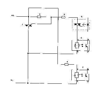
Fig. 1 is a circuit diagram showing an example of an output
power control circuit useful in this invention.
Fig. 2 is a circuit diagram showing another example of an
output power control circuit.
Fig. 3 is a circuit diagram showing an example of control
circuit useful in this invention.
Fig. 4 is a circuit diagram showing an exemplary application
for this invention.
Fig. 5 is a diagram illustrating the functions of the
application example of Fig. 4.

DETATT-Tm DESCRIPTION OF THE lNv~ lON:
Fig. 1 shows an example of an output power control circuit
useful in this invention. We shall now explain the function
of the circuit in this example. The control terminal of a
bidirectional power switching device such as a triac 1 is
connected to an optically coupled bidirectional switching
device 5 through current limiting resistor 3 and through the
input of an optical coupler 6 to the power output terminal 41
thus enabling a current, flowing from the output power
terminal through components 3 and 6 and controlled by
component 5 to change the status of the bidirectional power
switching device. The said control current will activate the
optical coupler 6 only when the output power switching device
1 is in the conducting state. A second optical coupler 7
will be activated when a voltage is present across the output
switching device by the current flowing through resistor 4
which is connected to output terminal 40.
Fig. 2 is a circuit diagram of another example of an output
power control circuit useful in this invention. We shall now
explain the circuit in this example. The control terminals
of two unidirectional power switching devices such as
thyristors 8, 9 are connected to input terminals of a bridge
rectifier 13 through a current limiting device 12. A
unidirectional switching device 14 is connected to the
positive output terminal of the bridge rectifier through the
input of an optical isolator 6.
The control terminal of the unidirectional switching device
14 is connected to the positive terminal of the bridge
rectifier 13 through resistor 16 and the input of optical
coupler 7. The collector of transistor 15 is connected to
the control terminal of unidirectional switching device 14
and the emitter is connected to the negative terminal of
bridge rectifier 13 together with the negative terminal of
unidirectional switching device 14. The base terminal of
transistor 15 is connected through resistor 17 and the input
of device 7 to the positive terminal of bridge rectifier 13.

The base terminal of transistor 15 is connected also to the
output of optical switching device 5 through resistor 18. The
negative output terminal of optical switching device 5 is
connected to the negative terminal of bridge rectifier 13.
Let us assume that a voltage is present across output
terminal 40 and 41. This voltage will be rectified by bridge
rectifier 13 and appear as a DC voltage on the inputs of
optical switching devices 6 and 7. Because of the resistors
16 and 17 the said DC voltage will change into a DC current
flowing through optical switching device 7 into the base and
collector of transistor 15. Optical switching device 7 will
be activated. If, under said conditions, optical switching
device 5 is activated the current flowing in current limiting
device 17 will flow into the output terminal of optical
switching device 5 through current limiting resistor 18
instead of into the base terminal of transistor 15. Under
these conditions the current in resistor 16 will flow into
the control terminal of unidirectional switching device 14
instead of into the collector of transistor 15 thus
activating unidirectional switching device 14. The said
switching device will start to conduct current through
optical switching device 6 and through bridge rectifier 13,
current limiting device 12 and into the control terminals of
unidirectional power switching devices 8 and 9 thus
activating that power switching device which is in the
forward direction with respect to the voltage across output
terminals 40 and 41.
Fig. 3 is a circuit diagram showing an example of a control
circuit useful in this invention. The optical switching
devices shown in this diagram are the links between this
circuit and the circuit described in fig. 1 and fig. 2. In
this circuit transistor 32 will activate optical switching
device 5 through resistor 21 when a control voltage is
present at the control input terminal 38. At the same time
one input of exclusive NOR gates 24 and 25 is changed from
high to low. Activating optical switching device 5 will force
the output circuit into the conducting state, as described

3 3
with reference to fig. 1 and fig. 2; thereby optical
switching device 7 will be deactivated as no voltage exists
across output terminals 40 and 41 as described with reference
to fig. 1 and fig. 2. Optically coupled switching device 6
will be activated by the current flowing into the control
terminal of the output switching device, as described with
reference to fig. 1 and fig. 2. This means that input B of
exclusive NOR gates 24 and 25 will change status from low to
high and thereby the output voltage from gates 24 and 25 will
be zero. Exclusive NOR gate 31 will also have zero volts
output and the alarm output 37 will not be active. If the
current in the output power switching device, described with
reference to fig. 1 and 2, is interrupted, either by missing
source voltage or disconnection of the load, optically
coupled switching device 6 will deactivate and input B of
gate 25 will change from high to low which will change the
output of gate 25 to a high voltage. This voltage will
charge the integrator formed by capacitor 30 and resistor 29.
After approx 50 mS the voltage of a capacitor 30 has reached
a value approx 50~ of V+, which will make gate 31 change
output state; thereby current will flow through resistor 34
into base of transistor 35 thus activating the alarm output
37. The alarm output will be active as long as the erroneous
condition persists. Let us assume that the error has been
corrected. If the voltage of the control input is removed,
optically coupled switching device 5 will be deactivated and
input A of gates 24 and 25 will change to a high voltage, and
at the same time optically coupled switching device 6 will be
deactivated as no control current is flowing to the output
power switching device as described with reference to figs.
1 and 2. Furthermore, optically coupled switching device 7
will be activated as there will be voltage across the output
terminals 40 and 41 as described with reference to figs. 1
and 2. This means that the voltage at input B of gates 24
and 25 will change to a low voltage and thereby gates 24 and
25 will provide a low output voltage so that the alarm output
will not be activated. If the voltage across output terminals
40 and 41 is disconnected, either by missing source voltage
,~ ~

or interruption of the load circuit, optically coupled
switching device 7 will be deactivated and input B of gate 24
will change to high, which will change the output of gate 24
to high. Capacitor 30 will be charged through diode 27 and
resistor 29 until the voltage has reached approximately 50~
of the supply voltage V+, when gate 31 will turn on
transistor 35 through resistor 34 and thus turn on the alarm
output.
We shall now explain the function of the circuit of fig. 4.
Let us assume that the voltage source is the mains voltage.
When switching device S is closed, the output power switching
device of this invention is turned on, as explained with
reference to figs. 1 and 2, and current will flow from the
voltage source to the load. When switching device 5 is again
opened the output power switching device of this invention
will turn off the current. If, with switching device 5 open,
the source voltage is switched off, or the load circuit fails
open circuit, or the output power switching device of this
invention fails short circuit, then the alarm output 37 will
be activated as explained with reference to fig. 1, fig. 2
and fig. 3. If with switching device 5 closed, the source
voltage is switched off or the load circuit fails open
circuit, or the output power switching device of this
invention fails either open circuit or short circuit and
thereby opens the fuse, then the alarm output will be
activated as explained with reference to fig. 1, fig. 2 and
fig. 3.
Fig. 5 illustrates the function of the application example of
fig. 4 by showing the status of various conditions during
four alarm examples identified by numbers at the bottom of
the diagram. Alarm examples 1 and 2 indicate that the
continuity of either the load or the load connections has
been interrupted. Alarm examples 3 and 4 indicate that the
source voltage has failed.

3 3
The optically coupled switching devices utilized may be
replaced by magnetically coupled switching devices, for
example relays.
, ~
, ,~

Dessin représentatif
Une figure unique qui représente un dessin illustrant l'invention.
États administratifs

2024-08-01 : Dans le cadre de la transition vers les Brevets de nouvelle génération (BNG), la base de données sur les brevets canadiens (BDBC) contient désormais un Historique d'événement plus détaillé, qui reproduit le Journal des événements de notre nouvelle solution interne.

Veuillez noter que les événements débutant par « Inactive : » se réfèrent à des événements qui ne sont plus utilisés dans notre nouvelle solution interne.

Pour une meilleure compréhension de l'état de la demande ou brevet qui figure sur cette page, la rubrique Mise en garde , et les descriptions de Brevet , Historique d'événement , Taxes périodiques et Historique des paiements devraient être consultées.

Historique d'événement

Description Date
Inactive : Périmé (brevet - nouvelle loi) 2013-09-15
Inactive : Lettre officielle 2012-11-16
Inactive : Renversement de l'état sera réputé périmé 2012-11-15
Lettre envoyée 2012-09-17
Inactive : CIB de MCD 2006-03-11
Lettre envoyée 2005-09-22
Inactive : Lettre officielle 2005-09-12
Lettre envoyée 2000-09-13
Inactive : Transfert individuel 1998-11-18
Accordé par délivrance 1998-06-16
Préoctroi 1998-01-28
Inactive : Taxe finale reçue 1998-01-28
Lettre envoyée 1997-10-20
Un avis d'acceptation est envoyé 1997-10-20
Inactive : Renseign. sur l'état - Complets dès date d'ent. journ. 1997-10-15
Inactive : Dem. traitée sur TS dès date d'ent. journal 1997-10-15
Inactive : CIB attribuée 1997-09-17
Inactive : CIB enlevée 1997-09-17
Inactive : CIB en 1re position 1997-09-17
Inactive : CIB enlevée 1997-09-17
Inactive : CIB attribuée 1997-09-17
Inactive : Approuvée aux fins d'acceptation (AFA) 1997-09-12
Demande publiée (accessible au public) 1994-07-27
Exigences pour une requête d'examen - jugée conforme 1994-01-26
Toutes les exigences pour l'examen - jugée conforme 1994-01-26

Historique d'abandonnement

Il n'y a pas d'historique d'abandonnement

Taxes périodiques

Le dernier paiement a été reçu le 1997-08-08

Avis : Si le paiement en totalité n'a pas été reçu au plus tard à la date indiquée, une taxe supplémentaire peut être imposée, soit une des taxes suivantes :

  • taxe de rétablissement ;
  • taxe pour paiement en souffrance ; ou
  • taxe additionnelle pour le renversement d'une péremption réputée.

Veuillez vous référer à la page web des taxes sur les brevets de l'OPIC pour voir tous les montants actuels des taxes.

Titulaires au dossier

Les titulaires actuels et antérieures au dossier sont affichés en ordre alphabétique.

Titulaires actuels au dossier
CARLO GAVAZZI SERVICES AG
Titulaires antérieures au dossier
OVE STYHM KRISTENSEN
Les propriétaires antérieurs qui ne figurent pas dans la liste des « Propriétaires au dossier » apparaîtront dans d'autres documents au dossier.
Documents

Pour visionner les fichiers sélectionnés, entrer le code reCAPTCHA :


Pour visualiser une image, cliquer sur un lien dans la colonne description du document. Pour télécharger l'image (les images), cliquer l'une ou plusieurs cases à cocher dans la première colonne et ensuite cliquer sur le bouton "Télécharger sélection en format PDF (archive Zip)" ou le bouton "Télécharger sélection (en un fichier PDF fusionné)".

Liste des documents de brevet publiés et non publiés sur la BDBC .

Si vous avez des difficultés à accéder au contenu, veuillez communiquer avec le Centre de services à la clientèle au 1-866-997-1936, ou envoyer un courriel au Centre de service à la clientèle de l'OPIC.


Description du
Document 
Date
(aaaa-mm-jj) 
Nombre de pages   Taille de l'image (Ko) 
Page couverture 1998-06-15 1 38
Abrégé 1995-08-26 1 27
Description 1995-08-26 6 311
Page couverture 1995-08-26 1 45
Dessins 1995-08-26 5 149
Revendications 1995-08-26 2 78
Dessin représentatif 1998-06-15 1 4
Dessins 1997-08-21 5 53
Abrégé 1997-08-21 1 17
Description 1997-08-21 6 254
Revendications 1997-08-21 2 56
Avis du commissaire - Demande jugée acceptable 1997-10-20 1 165
Courtoisie - Certificat d'enregistrement (document(s) connexe(s)) 1999-01-19 1 114
Correspondance 1998-01-28 1 40
Taxes 1998-08-11 1 42
Correspondance 2000-09-13 2 53
Taxes 1997-08-08 1 34
Correspondance 2005-09-12 1 20
Correspondance 2005-09-22 1 17
Correspondance 2012-11-16 1 12
Taxes 1996-08-08 1 38
Taxes 1995-08-10 1 38
Correspondance de la poursuite 1997-07-28 5 181
Demande de l'examinateur 1997-01-28 3 134
Correspondance de la poursuite 1994-08-24 1 22
Courtoisie - Lettre du bureau 1994-04-15 1 53
Correspondance reliée au PCT 1994-01-26 1 29
Correspondance reliée au PCT 1994-04-22 1 42